
Related Manuals for Common CGR-01


Summary of Contents for Common CGR-01
- Page 1 ROTARY GAS METERS Type COMMON S.A. ul. Aleksandrowska 67/93 CGR-01 91-205 Łódź, Poland Tel: +48 42 253 66 00 Fax: +48 42 253 66 99 MANUAL CGR / IU09 Łódź 2009 PLEASE READ THIS MANUAL BEFORE INSTALLING THE ROTARY GAS METER AND PUTTING IT INTO OPERATION...
-
Page 2: Table Of Contents
TABLE OF CONTENTS Page PURPOSE AND CONDITIONS OF USE CONSTRUCTION AND OPERATING PRINCIPLE III. METER OUTPUT GAS METER MARKING PACKING, TRANSPORTATION AND STORAGE METER INSTALLATION AND PUTTING INTO OPERATION VII. INSPECTION & MAINTENANCE, MALFUNCTIONS, REPAIRS VIII. ACCESSORIES... -
Page 3: Purpose And Conditions Of Use
IIC, with air. Physical parameters of most popular gases and gas mixtures that can be measured by CGR-01 are presented in table 1. The maximum design pressure for housings of CGR-01 rotary gas meters is: 1,6 MPa for gas meters with PN16 connections, 2 MPa for gas meters with PN20 (ANSI150) connections. - Page 4 Table 1. Physical properties of most popular gases and gas mixtures that may be measured with the CGR-01 Rotary Gas Meters. Density specified at 101,325 kPa and 20°C . Gas or gas Chemical Density Density Gas meter mixture symbol related to air version ρ...
- Page 5 Figure 1. Pressure loss coefficient as a function of relative flow Q/Qmax.
- Page 6 Table 2. Essential metrological parameters of CGR-01 rotary gas meters. pulser constant cyclic pressure loss Series maximum nominal pulser constant (approximately) minimum flow [m /h ] volume at Q meter size flow diameter turn down ratio (rangeability) [Pa] [mm] [pulses/m...
-
Page 7: Construction And Operating Principle
Index mechanism sums the volume, which passed through the meter, and that value is presented on the counter (the counter is of drums design). Figure. 2. The working principle of CGR-01 rotary gas meter. Rotary gas meter (figure 3) consists of four major units: External housing. -
Page 9: Meter Output
, which allows convenient visual readout of the counter from almost any direction. Figure 4. The location of meter outputs of the CGR-01 rotary gas meter. Electrical signals outputs. There can be two types of electrical signals outputs: LF-low frequency and HF-high frequency. The index can be equipped with maximum two sockets and... - Page 10 One of the HF pulsers installed in the index can act as the test element in CGR-01 gas meter. If the index is not equipped with HF pulser, than for the time of tests the gas meter can be equipped with the external test element (please refer to chapter VII).
- Page 11 According to conditions of use, CGR-01 gas meters should be equipped with pulsers (pulse generators) which assure the safety level of at least II 2G Ex ib IIC T4. That condition is met by the following example of pulsers mounted in the index: HF type Bi1-EG05-Y1 manufactured by Hans Turck GmbH;...
- Page 12 Meter outputs for temperature measurement. Temperature measurement in CGR-01 rotary gas meter is optional; it is not supplied as standard. Meter outputs for temperature measurement are located on both sides of the external housing (figure 4). Temperature pockets are fixed in holes in the external housing (figure 6) and their length is: L=110mm for “171”...
-
Page 13: Gas Meter Marking
IV. GAS METER MARKING Information about basic technical parameters of the gas meter, its serial number and the year of production are specified on nameplates (figure 7 & figure 8), which are fixed by screws to the index. Figure 7. Nameplates for a standard version of a gas meter (“IIA” & “IIB”) Figure 8. - Page 14 Before the validity of verification expires, the gas meter should be presented to authorized laboratory for reverification (please take into account the time needed by the laboratory). Common S.A. offers reverification, and if needed, also regulation and repairs of the gas meters.
-
Page 15: Packing, Transportation And Storage
Each rotary gas meter manufactured by Common S.A. is delivered with the following equipment: plug: 6-PIN “Tuchel” C091 31H006 100 2, which can be used for connecting a volume converter or data logger to the low frequency electrical output of the meter (unless the volume converter is already attached to the meter by the manufacturer);... - Page 16 Figure 10. The package for CGR-01 series “171” rotary gas meters.
- Page 17 Figure 11. The package for CGR-01 series “241” rotary gas meters.
-
Page 18: Meter Installation And Putting Into Operation
25% , and for no more than 30 minutes. CGR-01 rotary gas meters can operate in four positions, as shown below (figure 12 a, b, c, d): Figure 12. Possible operating positions of CGR-01 rotary gas meter. - Page 19 EN 12480:2002. Dimensions given in table 4a and 4b, presented on figure 14, may be helpful during designing the place of installation for the gas meter. Table 4a. The main dimensions and weights of CGR-01 rotary gas meters. Cyclic Weight...
- Page 20 The gas meter’s manufacturer is not responsible for gas meter damage, or gas meter blocking, caused by poor filtration of gas. Figure 14. The main dimensions of CGR-01 rotary gas meters. The end user should note the possible risk related to the change of the gas flow rate in the piping.
- Page 21 4 bar g (figure 15b) - special version. Each standard version of CGR-01 gas meter may be changed into special version by installing the check valve for oil filling under pressure up to 4 bar g.
- Page 22 If the gas meter is equipped with the oil fill plug (figure 15a), oil can be poured inside through the upper hole in the front cover, after removing the plug. After installation, before filling the meter with oil (and before putting it into operation), please make sure that the oil fill plug (or check valve) is located on the upper side of the meter.
- Page 23 The dimensions of restricting flow orifice plate are selected individually for given nominal diameter, gas flow, gas pressure, and gas temperature. Upon request Common S.A. may design and supply proper restricting flow orifice plate. After installing the gas meter, please pay attention to counter indications. Each cylinder in the counter should rotate smoothly, and after complete rotation, it should rotate the neighbor cylinder to the left, of 1/10 of a turn.
-
Page 24: Inspection & Maintenance, Malfunctions, Repairs
VII. INSPECTION & MAINTENANCE, MALFUNCTIONS, REPAIRS In case of doubt as to the indications of the gas meter, please remove it from the piping and please send it to the appropriate laboratory to verify the metrological characteristics. The test element can be used during verification/checking in the laboratory, without breaking the legal seal. - Page 25 That screw should be sealed by the security seal. CGR-01 gas meters are equipped with rotors’ bearings lubrication system and internal gears lubrication system. Other mechanisms of the rotary meters have self lubricated bearings.
-
Page 26: Accessories
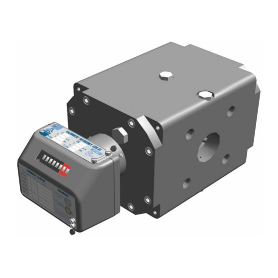
Oil replenishment, without the need of decreasing the gas pressure to atmospheric pressure, is possible for special version of CGR-01 rotary gas meters, equipped with the check valve for oil filling under gas pressure up to 4 bar g (figure 15b). The ordinary syringe (which is delivered with the bottle with oil) is used for pouring the oil into the meter (through the check valve). - Page 27 The example of the complete measurement set is presented on figure 19. Figure 19. The measurement set with CGR-01 gas meter and CMK-02 volume converter (volume converter mounted on the gas meter).
- Page 28 Figure 20. CKMT 3-way valve manufactured by Common S.A. The security seal protects the position of the lever of the 3-way valve. Opening and closing the valve is allowed only under the supervision of a representative of the gas plant, followed by a further sealing of the lever by protection seal.
Need help?
Do you have a question about the CGR-01 and is the answer not in the manual?
Questions and answers