Table of Contents
Advertisement
Advertisement
Table of Contents

Related Manuals for Common CGR-01 Series


Summary of Contents for Common CGR-01 Series
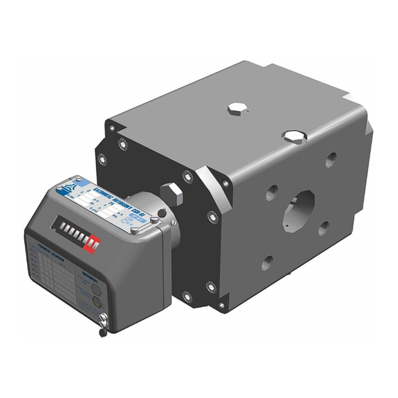
- Page 1 ROTARY GAS METERS series COMMON S.A. ul. Aleksandrowska 67/93 CGR-01 91-205 Łódź, Poland Phone no.: +48 42 2536600 Fax: +48 42 2536699 OPERATION MANUAL (Technical manual) CGR / IO12 / MID July 2012 PLEASE READ THE OPERATION MANUAL BEFORE INSTALLING...
-
Page 2: Table Of Contents
Table of Contents Page INTENDED USE AND CONDITIONS OF USE DESIGN AND FUNCTION III. READOUT DEVICE AND MEASUREMENT OUTPUTS LABELLING AND PROTECTION PACKAGING, TRANSPORT AND STORAGE INSTALLATION AND OPERATION VII. OPERATION MONITORING, MAINTENANCE, FAILURES, REPAIRS VIII. ADDITIONAL EQUIPMENT LIST OF STANDARDS AND TECHNICAL SPECIFICATIONS CGR/IO12/MID... -
Page 3: Intended Use And Conditions Of Use
IIA and IIB (and group IIC for the special purpose embodiment) with air. Table 1 lists the physical properties of the most common gases and gas mixtures that may be measured with CGR-01 gas meters. - Page 4 PN-EN 60947-5-2:2011 (EN 60947-5-2:2007), PN-EN 60947-5-6:2002 (EN 60947-5-6:2000). Table 1. Physical properties of the most common gases and gas mixtures that may be measured with CGR-01 gas meters. Densities under pressure of 101.325 kPa at Chemical...
- Page 5 Fig. 1. The pressure drop ratio as a function of the relative flow Q/Q CGR/IO12/MID...
- Page 6 Table 2a. Basic metrological parameters of CGR-01 gas meters in aluminium bodies. ∆p Gas meter cyclic loss of pressure emitter constant Gas meter Maximum nominal emitter constant series minimum flow in [m /h ] flow (approximate) volume at Q diameter size scale: [Pa]...
- Page 7 Table 2b. Basic metrological parameters of CGR-01 gas meters in cast iron bodies. ∆p Gas meter emitter constant Gas meter Maximum loss of pressure at nominal series cyclic volume emitter constant (approximate) flow minimum flow in [m /h ] diameter size scale [Pa]...
-
Page 8: Design And Function
II. DESIGN AND FUNCTION The rotary gas meter is a volumetric rotary machine based on the principle of proportionality of the speed of rotation of rotors to the actual volume of gas flowing through the gas meter at particular pressure and temperature conditions. The gas flowing into the gas meter (Fig. 2) fills the measurement chamber and the inlet overpressure causes rotation of rotors and transport of a portion of gas to the gas meter outlet. - Page 9 CGR/IO12/MID...
- Page 10 Fig. 3. Cross-section of the rotary gas meter CGR-01 CGR/IO12/MID...
-
Page 11: Readout Device And Measurement Outputs
III. READOUT DEVICE AND MEASUREMENT OUTPUTS The gas meter CGR-01 is equipped with a readout device in the form of a mechanical counter and electric signal outputs, a pressure measurement output and temperature measurement output (optional). The outlets allow to monitor the gas meter operation and to connect the external equipment. - Page 12 two inductive high frequency emitters (HF), and with a control circuit featuring a normally closed reed relay switch AFK or, alternatively, any other emitter. The reed relay emitters LFK are designed to work with a battery-powered or grid/battery- powered data logger and volume converter located in the vicinity of the gas meter (up to ca. 2 m).
- Page 13 LFI type Si5-K09-Y1-LF by Hans Turck GmbH; II 1G Ex ia IIC T6. LFK type CLFK-02 by Common S.A. II 2G Ex ia IIC T6. (1) – required linear characteristics of the emitter power circuit. Acceptable intrinsic safety parameters = 20 V DC = 20 V DC = 15.5 V DC...
- Page 14 Temperature measurement outlet. The turbine gas meter CGR-01 allows temperature measurements only when delivered as a special order version; temperature measurements are not available in the standard version. Temperature measurement outlets are located at both sides of the main body (Fig. 4). The body openings are complete with temperature pockets (Fig.
- Page 15 Mechanical counter outlet (option) The gas meter may be optionally equipped with a mechanical outlet. The mechanical outlet may be used to drive external, removable devices connected to the gas meter counter. A paddled tip of the counter shaft is located on the right side of the counter and covered by a protective cap.
-
Page 16: Labelling And Protection
IV. LABELLING AND PROTECTION Information on the basic technical parameters of the gas meter along with the serial number and manufacture year is listed on rating plates (Figs. 8a and 8b) bolted to the counter casing. Fig. 8a. Type plates – standard version IIA and IIB Fig. - Page 17 (one should also provide for the waiting time before the actual legal approval date) Common S.A. offers secondary verification at the manufacturer's laboratory, allowing for adjustments or repairs of the gas meters, if required.
-
Page 18: Packaging, Transport And Storage
Every rotary gas meter produced by Common S.A. is supplied with the following: a 6-pin Amphenol-Tuchel C091 31H006 100 2 plug to be used for connecting a converter or data logger to the low frequency electric signal outlet;... - Page 19 Fig. 11a & 11b. Packaging of the CGR-01 gas meters series “171” & “241” CGR/IO12/MID...
-
Page 20: Installation And Operation
VI. INSTALLATION AND OPERATION Before installing the gas meter ensure that it is suitable for the system's operational parameters. In particular, following type plate information should be taken into consideration: Acceptable gas meter gauge pressure [MPa], labelled p Maximum actual flow [m /h], labelled Q Maximum load of the gas meter, Q , may be exceeded... - Page 21 Gas meters should not be installed at the lowest point of the system lines, as condensate and impurities may accumulate in that area. The rotary gas meters can be used both indoors in stabilized temperature conditions and outdoors (open location). In the latter case, it is recommended that the gas meter is shielded from direct exposure to atmospheric factors (metal containers, casings, roofs, shields etc.) The gas meter must be placed between pipes of appropriate nominal diameter, with axial alignment of the gas meter relative to the pipes according to gas industry regulations.
- Page 22 Table 4b. Basic dimensions and weights of CGR-01 gas meters in cast iron bodies. Weight at V cycle G10w 0.50 G16w 0.50 G25w 0.50 G40p 0.50 G40w 0.81 G65s 0.50 G65p 0.81 G65w 1.24 G100s 0.81 G100p 1.24 G100s 0.81 G100p 1.24 G100w...
- Page 23 Following oils may be used with gases listed in Table 1: Lubrina L12 rotary gas meter oil (distributed by Common S.A.); VR09 rotary gas meter oil (distributed by Common S.A.);...
- Page 24 Other types of oils should be used for lubrication of gas meters in cases when the gas flowing through the meter is other than one of the gases listed in Table 1. In such cases, consult the oil type with the manufacturer of the gas meter! Oil level should be controlled during priming and subsequent refills.
- Page 25 Fig. 15. Oil filler plug. Caution! Gas pressure inside the gas meter should be reduced to atmospheric level before removal of the oil filler plug. If the gas meter is equipped with a pressure valve (Fig. 15b), oil may be refilled without reducing the system pressure to atmospheric level.
- Page 26 Common S.A. may design and deliver appropriate orifice at customer's request. Counter readout correctness should be checked after installing the gas meter. Every barrel of the counter should turn smoothly and a full turn of a barrel should turn the neighbouring left barrel by 1/10 of a full turn.
-
Page 27: Operation Monitoring, Maintenance, Failures, Repairs
VII. OPERATION MONITORING, MAINTENANCE, FAILURES, REPAIRS In any doubt regarding the correctness of gas meter readings, the gas meter should be removed from the system and submitted to an appropriate laboratory for verification of its metrological characteristics. The test may be performed using the control element, without breaking the legal approval seal. -
Page 28: Additional Equipment
the Namur standard) emitter signal to be obtained. This should be achieved with ca. 0.5 mm spacing between the emitter head and the inductive element (Fig. 17b). After completion of the test and removal of the control element, the hole should be tightly closed using a plug. A protection seal should be placed on the plug. - Page 29 VIII. ADDITIONAL EQUIPMENT Oil refills in pressurized conditions. It is possible to refill oil without the need to reduce the gas pressure to the atmospheric level when using a special version of the CGR-01 gas meter equipped with a pressure valve (Fig. 15b).
- Page 30 Common S.A. manufactures such devices, e.g. battery/grid-powered volume converters CMK-02 and data loggers CRS-03, CRI-02. Common S.A. may deliver these devices by special orders, together with installation services. Figure 19 presents an example installation of this type.
- Page 31 Fig. 20. A three-way CKMT valve The valve handle position is secured by a seal. The valve may be operated only under supervision of the gas company representative; after operation, the handle is again secured with an installation seal. The temperature signal is collected from the emitter installed in appropriate temperature pocket in the inflow section (upstream the gas meter) (Fig.
-
Page 32: List Of Standards And Technical Specifications
Note: Common S.A. reserves the right to modify the design of the gas meters while retaining the compliance with relevant standards and requirements regarding accuracy and safety of operation.
Need help?
Do you have a question about the CGR-01 Series and is the answer not in the manual?
Questions and answers