
Related Manuals for Common CGT-02 Series


Summary of Contents for Common CGT-02 Series
- Page 1 TURBINE GAS METERS series CGT-02 OPERATION MANUAL CGT – OM – 18 February 2018 PLEASE READ THE OPERATION MANUAL BEFORE INSTALLING AND OPERATING THE GAS METER...
-
Page 2: Table Of Contents
Table of Contents Page INTENDED USE AND CONDITIONS OF USE DESIGN AND FUNCTION III. READOUT DEVICE AND MEASUREMENT OUTPUTS LABELING AND SEALING PACKAGING, TRANSPORT AND STORAGE INSTALLATION AND OPERATION VII. OPERATION MONITORING, MAINTENANCE, FAILURES, REPAIRS VIII. ADDITIONAL EQUIPMENT LIST OF STANDARDS AND TECHNICAL SPECIFICATIONS... -
Page 3: Intended Use And Conditions Of Use
IIA and IIB. There are also special versions of meters for group IIC. Table 1 lists the physical properties of the most common gases and gas mixtures that may be measured with CGT-02 gas meters. The gas meters are produced with the following connection types: PN10, PN16, PN20 (ANSI150), PN25, PN40, PN50 (ANSI300), PN63/PN64, PN100, PN110 (ANSI600). - Page 4 Requirements met by the use of LF and HF pulse emitters (NAMUR) compliant with the following harmonized standards: EN 60947-5-2:2007, EN 60947-5-6:2000). Table 1. Physical properties of the most common gases and gas mixtures that may be measured with CGT-02 gas meters. Densities are specified under pressure of 101.325 kPa at 20...
- Page 5 – relative gas density (related to air) according to Table 1, 101 [kPa] ), – atmospheric pressure (p – gauge pressure at meter’s inlet [kPa], Wpd – pressure drop coefficient according to Figure 1. p – pressure drop at Qmax according to Table 2 [Pa]. COMMON S.A. CGT-OM-18 february.2018...
- Page 6 Q [m Fig. 1. Wpd pressure drop coefficient as a function of relative flux Q/Qmax...
- Page 7 Table2. NOTE: For gas meters equipped with all options (2 HF sensors on the turbine wheel & 2 HF sensors on the reference wheel & 2 thermowells) the ∆p pressure drop can be increased by 20%. COMMON S.A. CGT-OM-18 february.2018...
-
Page 8: Design And Function
The counter mechanism totals up the volume flowing through the device, and an 8-digit counter indicates the total volume. Each gas meter of the CGT-02 series is verified in the range of Q to Q (Table 2), and in that range the accuracy of the meter is verified. - Page 9 maintenance-free (without external lubrication, with spare quantity of grease in bearings); with special valve for periodic external lubrication (with a lubrication kit); with piston pump for external lubrication. The CGT-02 series gas meters can be equipped with piston pumps of the following four types: P1 – with pushbutton, ≤...
-
Page 10: Readout Device And Measurement Outputs
D2 – with lever, ≤ 6.3 [MPa], DN200, DN250, DN300, DN400, D3 – with lever, ≤ 11 [MPa], 6.3 [ MPa] < p DN200, DN250, DN300, DN400. Typical DN50 gas meters are not adapted for external lubrication. These meters can be optionally equipped with piston pump or lubrication valve. - Page 11 Tuchel C091 31H006 100 2 or Lumberg 0332 06 plugs. Tuchel connections in CGT-02 gas meters are of the IP67 protection class. Table 3 presents possible connections of emitters to individual electric signal output sockets. COMMON S.A. CGT-OM-18 february.2018...
- Page 12 Certificate No. KEMA 02ATEX1090X marking II 1G Ex ia IIC T4...T6 or II 2G Ex ia IIC T4...T6 type CLFK-03 by Common S.A. type CLFW-01 by Common S.A. type CLFW-02 by Common S.A. (1) – required linear characteristics of the emitter power circuit.
- Page 13 Intrinsic safety parameters of the emitters installed in the gas meter are listed on the type plate. The security level is also met by the following interchangeable transmitters: LFK type CLFK-04 manufactured by Common S.A. LFW type CLFW-04 manufactured by Common S.A. Acceptable intrinsic safety parameters...
- Page 14 The emitters should allow for at least 2G Ex ib IIC T5 Gb protection. These conditions are satisfied, for example, by the following emitters: CHFI-01 by Common S.A., equipped with Bi1-EG05-Y1 sensors (Hans Turck GmbH: Certificate No.: IECEx KEM 06.0036X, marking Ex ia IIC T4...T6 and Certificate No.: KEMA 02ATEX1090X marking...
- Page 15 LFK transmitters – reed contact and LFW with output type „open collector” CLFK-03 / CLFK-04 / CLFW-01 / CLFW-02 / CLFW-04 = 100 ÷ 2 k , Closed contact resistance Open contact resistance > 100 M , COMMON S.A. CGT-OM-18 february.2018...
- Page 16 Maximum switching frequency = 2 Hz . Inductive slot transmitters and inductive proximity transmitters in NAMUR standard. Si5-K09-Y1 Bi1-EG05-Y1 CHFI-01, CHFI-03 Maximum switching frequency = 2 Hz, = 0,5 kHz. Rated operating voltage Un = 8,2V Rated current of the non-activated sensor I >= 2,1mA Rated current of the energized sensor I <= 1,2mA...
- Page 17 (Fig. 8a and 8b) or plugged (Fig. 8c). Temperature sockets, when thermowells are not installed, must be plugged with ¼ NPT plugs (like on Fig. 7a). a) thermometer type 1 b) thermometer type 2 c) thermowell plugged Fig. 8 Temperature outputs with thermowells COMMON S.A. CGT-OM-18 february.2018...
-
Page 18: Labeling And Sealing
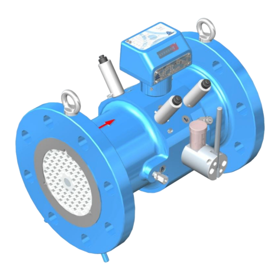
IV. LABELING AND SEALING Information on the basic technical parameters of the gas meter along with the serial number and manufacture year is listed on type plates (Figs. 9a and 9b) screwed to the index head. The direction of gas flow is marked on the upper side of the meter body (red arrow) and there are labels indicating electrical (HF) and mechanical outputs as well as pressure and temperature measurement outputs on the meter (Fig. - Page 19 (Fig. 13a) while seals P2, P3, P4, P5, P6, P7, P8, P9, P10 feature protection stamps (Fig. 13b). By request of the customer, the gas meter may be delivered along with the certificate that documents its verification/calibration. COMMON S.A. CGT-OM-18 february.2018...
- Page 20 The original verification stamp seal is required for the gas meter to be considered a legal measurement device. Installation seals placed at the connectors of the pressure transducers (P7), HF emitters (P8), temperature transducers (P9) and possibly at the mechanical output (P10), may feature stamps placed by the manufacturer, gas supplier or authorized installer.
- Page 21 Fig. 12b. Locations of seals on CGT-02 gas meter (version 2) COMMON S.A. CGT-OM-18 february.2018...
- Page 22 Fig. 13a. Original verification stamp sticker seal Fig. 13b. Security seals (examples)
-
Page 23: Packaging, Transport And Storage
Gas meters submitted for repair or renewal of legal verification should be sent in factory- made packaging or other packaging providing at least equal protection during transport. Each turbine gas meter by Common S.A. is supplied with the following: a 6-pin Tuchel C091 31H006 100 2 plug to be used for connecting a volume converter or recorder to the low frequency electric signal output (in case the converter has not been connected to the gas meter in the factory);... - Page 24 Fig. 14. Packaging of the DN50 turbine gas meter...
- Page 25 Fig. 15. Packaging of the DN50 turbine gas meter equipped with oil pump COMMON S.A. CGT-OM-18 february.2018...
- Page 26 Fig. 16. Packaging of DN80 and DN100 turbine gas meters...
- Page 27 Fig. 17. Packaging of DN150÷DN400 turbine gas meters COMMON S.A. CGT-OM-18 february.2018...
-
Page 28: Installation And Operation
VI. INSTALLATION AND OPERATION Before installing the gas meter ensure that it is suitable for the system's operational parameters. In particular, the following type plate information should be taken into consideration: Acceptable gas meter gauge pressure [MPa), labelled p ... - Page 29 PN100 PN110/ANSI600 PN10/PN16 cast PN20/ANSI150 iron PN25 PN10/PN16 PN20/ANSI150 215 101 124 182 171 PN25/PN40 PN50/ANSI300 steel PN63 PN100 PN110/ANSI600 PN10/PN16 cast PN20/ANSI150 iron PN25 PN10/PN16 PN20/ANSI150 208 231 141 PN25/PN40 PN50/ANSI300 steel PN63 PN100 PN110/ANSI600 COMMON S.A. CGT-OM-18 february.2018...
- Page 30 Table 3a part II. Basic dimensions and weights of CGT-02 turbine gas meters mass connection body (flange) mm mm mm mm mm mm mm mm mm PN10/PN16 cast PN20/ANSI150 iron PN25 PN10/PN16 PN20/ANSI150 PN25 265 212 240 223 333 168 30 55 PN40...
- Page 31 PN20/ANSI150 PN25 PN40 215 101 124 183 171 PN50/ANSI300 PN63 PN100 PN110/ANSI600 PN10 PN16 PN20/ANSI150 PN25 PN40 242 155 180 208 231 141 147 141 35 60 PN50/ANSI300 PN63 wersja Mo PN63 wersja Mn PN100 PN110/ANSI600 COMMON S.A. CGT-OM-18 february.2018...
- Page 32 Table 3b. Dimensions of the connections of CGT-02 turbine meters (DN50÷DN400). connection connection (flange) (flange) PN10 PN10/16 PN16 120.5 PN20/ANSI150 PN20/ANSI150 PN25/40 PN25 PN50/ANSI300 PN40 PN63 PN50/ANSI300 387.5 29.5 PN100 PN63 PN110/ANSI600 PN100 PN10/16 35.5 PN110/ANSI600 PN20/ANSI150 152.5 PN10 PN25/40 PN16 168.5 PN50/ANSI300...
- Page 33 Appropriate bolt lengths should be selected with consideration to dimensions listed in Tables 3a and 3b and the thickness of gaskets being used. Tables 5a and 5b list the required tightening bolt torque values for flange connections. COMMON S.A. CGT-OM-18 february.2018...
- Page 34 VII. Only the oil supplied with the gas meter should be used for this purpose. Following oils may be used with gases listed in Table 1: Lubrina L12 gas meter oil – distributed by Common S.A.; Lubrina L23 gas meter oil – distributed by Common S.A.;...
- Page 35 510 nominal diameters (DN) downstream the gas meter. The orifice dimensions are selected individually on the basis of the nominal diameter and gas flow, pressure and temperature. Common S.A. may design and deliver appropriate orifice at customer's request.
-
Page 36: Operation Monitoring, Maintenance, Failures, Repairs
VII. OPERATION MONITORING, MAINTENANCE, FAILURES, REPAIRS In any doubt regarding the correctness of gas meter readings, the gas meter should be removed from the system and submitted to an appropriate laboratory verification of its metrological characteristics. The test may be performed using the control element, without removing the legal verification seal. -
Page 37: Additional Equipment
Lubrication kit for lubricating gas meters equipped with lubrication check valve Gas meters CGT-02 series operating in HV positions can be adapted to external lubrication by means of syringes. These meters are equipped with a system of ducts to transport lubricating oil to the bearings and a special check valve. - Page 38 Fig. 20 Lubrication procedure of a gas meter equipped with a lubrication check valve LF Replaceable transmitters type CLFK-04 or CLFW-04 As the special execution the CGT-02 gas meters can be equipped with index housing adapter for replaceable transmitters. CLFK-04 (reed contact) or CLFW-04 (Wiegand) transmitters (rys.
- Page 39 CWSL Encoder can be connected to the optional mechanical output. There are 3 versions of (optional) Encoders available: CWSL-N, CWSL-A, CWSL-M (Fig. 23). Data sent from CWSL-N are equal to data on the index. Fig. 23 CWSL Encoder adapted for connection with the index of CGT-02 gas meter. COMMON S.A. CGT-OM-18 february.2018...
- Page 40 Common S.A. manufactures such devices, e.g. battery/grid- powered volume converters CMK and data loggers CRS. Common S.A. may deliver such devices on special orders, together with installation services. Exemplary installations are presented in Figs.
- Page 41 Unused electrical output sockets must remain plugged with factory-made plugs and installation seals. COMMON S.A. CGT-OM-18 february.2018...
-
Page 42: List Of Standards And Technical Specifications
Notice: Technical specification and construction of CGT-02 gas meters may change due to improvements made within the limits of certifications. This publication serves as general information only and all specifications are subject to confirmation by COMMON S.A.
Need help?
Do you have a question about the CGT-02 Series and is the answer not in the manual?
Questions and answers