Advertisement
Quick Links
If you have any questions regarding assembly or if parts are missing, DO NOT return this item to the
store where it was purchased. Please call our customer service number and have your instructions and
parts list ready to provide the model name, part name or factory number:
Pacific Standard Time: 8:30 a.m. - 4:30 p.m., Monday - Friday
Or visit our web site 24 hours a day, 7 days a week for product assistance at
THIS INSTRUCTION BOOKLET CONTAINS IMPORTANT SAFETY INFORMATION.
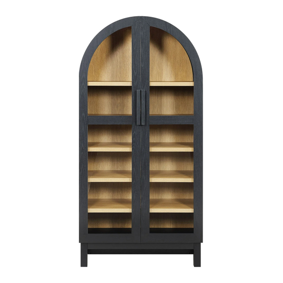
Juliet Arch Cabinet
Stock # BHF336158813005
# BHF336158813031
ADULT ASSEMBLY REQUIRED
www.whalenstyle.com
Or e-mail your request to parts@whalenfurniture.com
PLEASE READ AND KEEP FOR FUTURE REFERENCE.
Date 2023-11-21
1-866-942-5362
Rev. 0001-A
LOT NUMBER:
DATE PURCHASED:
/
/
Advertisement

Subscribe to Our Youtube Channel
Related Manuals for Better Homes and Gardens Juliet BHF336158813005


Summary of Contents for Better Homes and Gardens Juliet BHF336158813005
- Page 1 LOT NUMBER: DATE PURCHASED: Juliet Arch Cabinet Stock # BHF336158813005 # BHF336158813031 ADULT ASSEMBLY REQUIRED If you have any questions regarding assembly or if parts are missing, DO NOT return this item to the store where it was purchased. Please call our customer service number and have your instructions and parts list ready to provide the model name, part name or factory number: 1-866-942-5362 Pacific Standard Time: 8:30 a.m.
-
Page 2: Special Note
M A X I M U M R E C O M M E N D E D W E I G H T L O A D S MANUFACTURER: Whalen Furniture Manufacturing CATALOG: Juliet Arch Cabinet MODEL # BHF336158813005 / BHF336158813031 MAXIMUM LOAD 22.7 kg / 50 lb. - Page 3 IMPORTANT Before you begin: Open, identify and count all parts prior to assembly. Lay out parts on a flat and non-abrasive surface. You will need the parts identified on page 4, 5 and 6 of this instruction manuals. NOTE: IT IS VERY IMPORTANT TO USE GLUE WITH DOWELS. EXCESS GLUE CAN BE WIPED OFF WITH DAMP CLOTH.
- Page 4 Parts and Hardware List Please read completely through the instructions and verify that all listed parts and hardware are present before beginning assembly. A- Left Side Panel (Qty. 1) B- Right Side Panel (Qty. 1) C- Upper Fixed Shelf (Qty. 1) D- Lower Fixed Shelf (Qty.
- Page 5 Parts and Hardware List Please read completely through the instructions and verify that all listed parts and hardware are present before beginning assembly. M- Arch Left Stretcher N- Arch Right Stretcher O- Arch Middle Support (Qty. 1) (Qty. 1) (Qty. 2) P- Bottom Side Frame Q- Bottom Front / Back Stretcher R- Bottom Middle Stretcher...
- Page 6 Parts and Hardware List Please read completely through the instructions and verify that all listed parts and hardware are present before beginning assembly. (1) Cam Lock (2) Cam Bolt (3) M8 x 30 mm Wood Dowel (Qty. 42+2 extra) (Qty. 42+2 extra) (Qty.
- Page 7 Assembly Instructions ② x 12 NOTE: Please do not fully tighten all cam locks and screws until you finish assembling all parts. Once assembled, go back and fully tighten all cam locks and screws. This will make the assembly easier. 1.
- Page 8 Assembly Instructions ② x 12 3. Securely screw the Cam Bolts (2) into the designated small holes on the Upper Fixed Shelf (C) and Bottom Panel (E) using a Phillips screwdriver.
- Page 9 Assembly Instructions ⑩ x 2 ④ x 8 ⑧ x 2 4. Using the pilot holes as a guide, install 2 Magnetic Catches (8) to the Upper Fixed Shelf (C) with four 15 mm Washer Head Screws (4). 5. Repeat the same procedure to install two Catch Metal Plates (10) to the Bottom Panel (E). NOTE: It is recommended to insert the screw through the CENTER of oval holes on both magnetic catches and metal plates.
- Page 10 Assembly Instructions ③ x 12 6. Glue the Wood Dowels (3) into the inner holes on the Fixed Shelves (C and D) and Bottom Panel (E). NOTE: It is very important to use a small amount of glue on both ends of dowels and wipe away the excess glue immediately with a damp cloth.
- Page 11 Assembly Instructions The magnetic catches and pilot holes for hinges are oriented at the same direction. ① x 2 7. Orient and attach the Upper Fixed Shelf (C) to the Left Side Panel (A) by engaging 2 Cam Locks (1). Turn the cam locks with a Phillips screwdriver until securely locked onto the cam bolts.
- Page 12 Assembly Instructions The cam lock housings face the floor when the unit is turned upright. ① x 2 8. Orient and attach the Lower Fixed Shelf (D) to the Left Side Panel (A) by engaging 2 Cam Locks (1). Turn the cam locks with a Phillips screwdriver until securely locked onto the cam bolts.
- Page 13 Assembly Instructions Hinge mounting holes Cam locks face outward. The roller catch metal plate are ① x 2 located at the front of unit. 9. Orient and attach the Bottom Panel (E) to the Left Side Panel (A) by engaging 2 Cam Locks (1).
- Page 14 Assembly Instructions ① x 6 10. Repeat the previous procedures to attach the Right Side Panel (B) at the opposite end.
- Page 15 Assembly Instructions ② x 12 11. Securely screw the Cam Bolts (2) into the designated small holes on the Arch Frames (G, H, I and J). Tighten the cam bolts with a Phillips screwdriver.
- Page 16 Assembly Instructions ③ x 18 12. Glue 18 Wood Dowels (3) into the inner holes on the Arch Stretchers (L, M and N) and Arch Middle Supports (O) as shown.
- Page 17 Assembly Instructions Groove Groove ① x 2 13. Orient and attach the Arch Side Stretchers (L) to each Arch Front Frame (I and G) respectively by engaging one Cam Lock (1).
- Page 18 Assembly Instructions 14. Slide the side without pilot holes of Arch Curved Panel (K) into the grooves on the Arch Side Stretchers (L) until fully inserted into the groove on the Arch Front Frames (I and G).
- Page 19 Assembly Instructions The cam lock housings face outward. ① x 4 15. Attach one Arch Middle Support (O) and Arch Right Stretcher (N) to the Arch Right Front Frame (I) by engaging 2 Cam Locks (1). 16. Repeat the same procedure to attach the other Arch Middle Support (O) and Arch Left Stretcher (M) to the Arch Left Front Frame (G).
- Page 20 Assembly Instructions ① x 6 17. Align and attach the Arch Right Back Frame (J) to the Arch Stretchers (L and N) and Arch Middle Support (O) with 3 Cam Locks (1). Make sure that the Arch Curved Panel (K) fits securely into the groove of the Arch Right Back Frame (J).
- Page 21 Assembly Instructions ④ x 10 19. Firmly press the Arch Curved Panel (K) all the way to Arch Right Stretcher (N) and fasten it into place with five 15 mm Washer Head Screws (4). 20. Repeat the same procedure to fasten the other Arch Curved Panel (K) to the Arch Left Stretcher (M).
- Page 22 Assembly Instructions ① x 4 21. Combine the assembled arch with the middle wood dowels fully inserted. 22. Orient and position the assembled arch onto both Side Panels (A and B) and tighten with 4 Cam Locks (1).
- Page 23 Assembly Instructions 23. Insert two 45 mm Bolts (14) through the threaded inserts on the Arch Left Stretcher (M) and securely screw into the Arch Right Stretcher (N).
- Page 24 Assembly Instructions ② x 6 24. Securely screw the Cam Bolts (2) into the designated small holes on both Bottom Side Frames (P) using a Phillips screwdriver.
- Page 25 Assembly Instructions ③ x 10 25. Glue 10 Wood Dowels (3) into the holes run against cam bolt cross bore on the Bottom Stretchers (Q and R).
- Page 26 Assembly Instructions The wood dowels are located at upward. ① x 6 26. Align and attach both Bottom Stretchers (Q and R) to the Left Bottom Side Frame (P) with 3 Cam Locks (1). Turn the cam locks with a Phillips screwdriver until securely locked onto the cam bolts. 27.
- Page 27 Assembly Instructions ① x 8 28. Align and attach the assembled base to the Bottom Panel (E) by engaging 8 Cam Locks (1). Turn the cam locks with a Phillips screwdriver until securely locked onto the cam bolts. 29. Now, go back and securely tighten all the Cam Locks and Screws. Make sure that all the parts are tight and there are no gaps between the parts.
- Page 28 Assembly Instructions The adhesive tapes face outward. ④ x 38 30. Unfold the Back Panel (U) and align the pre-drilled holes against the curved edge with the pilot holes on both Arch Back Frames (H and J). And attach it in place with the 15 mm Washer Head Screws (4) provided.
- Page 29 Assembly Instructions x 12 31. Ask for assistance to lift the assembled unit upright and position it near the final location. 32. Insert the Shelf Pins (11) into the holes at your desired height. Make sure you place the four Shelf Pins (11) at the same level to level the shelf.
- Page 30 Assembly Instructions x 12 34. Extend the Door Hinges (V) and rest three hinge cups onto the cutouts of each Door Panel (S and T). Secure the Door Hinges (V) in place by using two 15 mm Nickel Screws (13) in each.
- Page 31 Assembly Instructions The roller faces bottom edge. ④ x 4 ⑨ x 2 35. Using the pilot holes as a guide, install one Roller Catch (9) to each Door (S and T) using two 15 mm Washer Head Screws (4) per catch. NOTE: It is recommended to insert the screw through the CENTER of oval holes on the roller catches.
- Page 32 Assembly Instructions ⑥ x 4 ⑦ x 4 36. Fasten two Round Strike Plates (7) to each Door (S and T) using two 15 mm Screws (6) in each.
- Page 33 Assembly Instructions 37. Ask for assistance to lift the doors upright and attach one Handle (W) to the front side of each Door (S and T) with two Handle Bolts (15) per handle.
- Page 34 Assembly Instructions Oval hole Round hole x 24 Depth Vertical Horizontal Adjustment Adjustment Adjustment 38. Pick up the Left Door (S) and align the hinge bases to the pilot holes on the Left Side Panel (A). 39. Insert two 15 mm Nickel Screws (13) through the CENTER of oval holes and move the doors up or down to the desired position, then fasten the Hinge Bases (V) into place.
- Page 35 Assembly Instructions x 20 43. Insert the Cam Lock Covers (12) onto the visible cam locks to conceal the cams.
- Page 36 Assembly Instructions 44. The installed Magnetic Catches (8) and Metal Plates (10) can be adjusted to ensure that the doors function properly. This can be done by moving them forward and backward to the desired position. 45. Adjust the Roller Catches (9) installed on both doors upward and downward to ensure proper engage.
- Page 37 Assembly Instructions Wooden stud Wall Short screw Nylon strap Wall Metal bracket Long screw Floor leveler Tools required (not included): Phillips screwdriver, stud finder, tape measure, pencil, power drill and 1/8” drill bit. 46. Position the assembled unit at the desired location and adjust the pre-attached floor levelers to correct tilting and level the doors against a wall.
- Page 38 FURNITURE TIPPING RESTRAINT YOUNG CHILDREN MAY BE INJURED BY TIPPING FURNITURE AND YOU MUST USE THIS TIPPING RESTRAINT TO ATTACH THIS UNIT TO THE WALL, TO PREVENT ACCIDENTS AND/OR INJURIES. THIS HARDWARE, MUST BE PROPERLY INSTALLED (FOLLOW ALL DIRECTIONS IN ORDER ON THIS INSTRUCTIONS), TO PROVIDE PROTECTION AGAINST THE UNEXPECTED TIPPING OF FURNITURE DUE TO IMPROPER USE.
-
Page 39: Quality Guarantee
Care and Maintenance Use a soft, clean cloth that will not scratch the surface when dusting. Use of furniture polish is not necessary. Should you choose to use polish, test first in an inconspicuous area. Using solvents of any kind on your furniture may damage your furniture’s finish. ... - Page 41 NÚMERO de LOTE:__________ FECHA de COMPRA: Gabinete de arco de Julieta Modelo # BHF336158813005 # BHF336158813031 ENSAMBLE REQUERIDO POR ADULTO Si tienen alguna pregunta acerca del ensamble o si alguna parte está faltante, no retorne esté producto a la tienda donde lo compro. Por favor llame a nuestro departamento de ayuda al cliente teniendo su instructivo y lista de partes para proveer el modelo, nombre de parte o el número de fábrica: 1-866-942-5362 Hora estándar del Pacífico: 8:30 a.m.
- Page 42 M Á X I M O P E S O R E C O M E N D A D O FABRICANTE: Whalen Furniture Manufacturing CATALOGO : Gabinete de arco de Julieta MODELO # BHF336158813005 / BHF336158813031 CARGA MAXIMA 22.7 kg / 50 lb. ESTA UNIDAD DEBE UTILIZARSE CON LOS PESOS MÁXIMOS INDICADOS.
- Page 43 Importante Antes de comenzar: Abra, identifique y cuente todas las partes antes del ensamble. Coloque las piezas sobre una superficie plana y no abrasiva. Tendrá las partes identificadas en la página 4, 5 y 6 de este manual de instrucciones. NOTA: ES MUY IMPORTANTE EL USO DE GOMA CON LAS CLAVIJAS DE MADERA.
- Page 44 Lista de partes y material de ferretería Por favor lea completamente las instrucciones y verifique que estén todas las partes y partes de ferretería antes de iniciar el ensamblado. A- Panel izquierdo (Cant. 1) B- Panel derecho (Cant. 1) C- Repisa fija superior (Cant. 1) D- Repisa fija inferior (Cant.
- Page 45 Lista de partes y material de ferretería Por favor lea completamente las instrucciones y verifique que estén todas las partes y partes de ferretería antes de iniciar el ensamblado. M- Soporte arco izquierdo N- Soporte arco derecho O- Soporte arco medio (Cant.
- Page 46 Lista de partes y material de ferretería Por favor lea completamente las instrucciones y verifique que estén todas las partes y partes de ferretería antes de iniciar el ensamblado. (1) Tuerca de fijación (2) Perno de fijación (3) Clavija de madera de M8 x 30 mm (Cant.
- Page 47 Instructivo de ensamble ② x 12 NOTA: Por favor no apriete completamente todos los pernos, hasta que termine con el ensamble de las partes. Después asegúrese de apretar todos los pernos. Esto hará el ensamble más fácil. 1. Desempacar la unidad y confirmar que se tiene todo el material de ferretería y partes requeridas. Ensamblar la unidad en un piso alfombrado o en el cartón vacío para evitar rasguños.
- Page 48 Instructivo de ensamble ② x 12 3. Atornillar los pernos de fijación (2) en los agujeros pequeños designados en la repisa fija superior (C) y en el panel inferior (E) usando el desarmador estrella.
- Page 49 Instructivo de ensamble ⑩ x 2 ④ x 8 ⑧ x 2 4. Usando los agujeros pilotos como guía, instalar 2 magnetos (8) a la repisa fija superior (C) con 4 pernos de cabeza de arandela de 15 mm (4). 5.
- Page 50 Instructivo de ensamble ③ x 12 6. Pegar las clavijas de madera (3) en los agujeros internos en las repisas fijas (C y D) y en el panel inferior (E). NOTA: Es importante usar una cantidad pequeña de pegamento en ambos lados de las clavijas y limpiar el exceso de pegamento inmediatamente con una toalla húmeda.
- Page 51 Instructivo de ensamble Los magnetos y los agujeros pilotos de las bisagras están orientadas en la misma dirección. ① x 2 7. Orientar y adjuntar la repisa fija superior (C) al panel izquierdo (A) empleando 2 tuercas de fijación (1). Voltear las tuercas de fijación con el desarmador estrella hasta trabar seguramente sobre los pernos de fijación.
- Page 52 Instructivo de ensamble Los espacios de las tuercas de fijación apuntan hacia el piso cuando la unidad está en posición vertical. ① x 2 8. Orientar y adjuntar la repisa fija inferior (D) al panel izquierdo (A) empleando 2 tuercas de fijación (1). Voltear las tuercas de fijación con el desarmador estrella hasta trabar sobre los pernos de fijación.
- Page 53 Instructivo de ensamble Agujeros de montaje de las bisagras Las tuercas de fijación apuntan hacia afuera. La placa de metal de la rueda está ① x 2 en el frente de la unidad. 9. Orientar y adjuntar el panel inferior (E) al panel izquierdo (A) empleando 2 tuercas de fijación (1).
- Page 54 Instructivo de ensamble ① x 6 10. Repetir el procedimiento previo para adjuntar el panel derecho (B) al extremo opuesto.
- Page 55 Instructivo de ensamble ② x 12 11. Atornillar los pernos de fijación (2) en los agujeros pequeños designados en los marcos arco (G, H, I y J). Apretar los pernos de fijación con el desarmador estrella.
- Page 56 Instructivo de ensamble ③ x 18 12. Pegar 18 clavijas de madera (3) en los agujeros internos en los soportes arco (L, M y N) y en los soportes arco medios (O) como se muestra.
- Page 57 Instructivo de ensamble Ranura Ranura ① x 2 13. Orientar y adjuntar los soportes arco laterales (L) a cada marco arco frontal (I y G) respectivamente empleando una tuerca de fijación (1).
- Page 58 Instructivo de ensamble 14. Deslizar el lado sin agujeros pilotos en el panel arco curveado (K) en las ranuras en los soportes arcos laterales (L) hasta insertar completamente en las ranuras en los marcos arco frontales (I y G).
- Page 59 Instructivo de ensamble Los espacios de las tuercas de fijación apuntan hacia afuera ① x 4 15. Adjuntar el soporte arco medio (O) y el soporte arco derecho (N) al marco arco derecho frontal (I) empleando 2 tuercas de fijación (1). 16.
- Page 60 Instructivo de ensamble ① x 6 17. Alinear y adjuntar el marco arco derecho posterior (J) a los soportes arco (L y N) y al soporte arco medio (O) con 3 tuercas de fijación (1). Asegurar de que el panel arco curveado (K) encaje en la ranura del marco arco derecho posterior (J).
- Page 61 Instructivo de ensamble ④ x 10 19. Presionar el panel arco curveado (K) todo el camino al soporte arco derecho (N) y sujetar en su lugar con 5 pernos de cabeza de arandela de 15 mm (4). 20. Repetir el mismo procedimiento para sujetar el otro panel arco curveado (K) al soporte arco izquierdo (M).
- Page 62 Instructivo de ensamble ① x 4 21. Combinar el arco ensamblado con las clavijas de madera medias insertadas completamente. 22. Orientar y poner el arco ensamblado sobre ambos paneles laterales (A y B) y sujetar con 4 tuercas de fijación 4 (1).
- Page 63 Instructivo de ensamble 23. Insertar 2 pernos de 45 mm (14) a través de los insertos roscados en el soporte arco izquierdo (M) y atornillar en el soporte arco derecho (N).
- Page 64 Instructivo de ensamble ② x 6 24. Atornillar los pernos de fijación (2) en los agujeros pequeños designados en ambos marcos laterales (P) usando el desarmador estrella.
- Page 65 Instructivo de ensamble ③ x 10 25. Pegar 10 clavijas de madera (3) en los agujeros que corren contra el espacio para pernos de fijación en los soportes inferiores (Q y R).
- Page 66 Instructivo de ensamble Las clavijas de madera estan localizadas arriba. ① x 6 26. Alinear y adjuntar ambos soportes inferiores (Q y R) al marco izquierdo inferior lateral (P) con 3 tuercas de fijación (1). Voltear las tuercas de fijación con el desarmador estrella hasta trabar sobre los pernos de fijación.
- Page 67 Instructivo de ensamble ① x 8 28. Alinear y adjuntar la base ensamblada al panel inferior (E) empleando 8 tuercas de fijación (1). Voltear las tuercas de fijación con el desarmador estrella hasta trabar sobre los pernos de fijación. 29. Ahora, volver y apretar todos los pernos y tuercas de fijación. Asegurar que todas las partes estén apretadas y de que no hay huecos entre las partes.
- Page 68 Instructivo de ensamble La cinta adhesiva apunta hacia afuera ④ x 38 30. Desdoblar el panel posterior (U) y alinear a los agujeros pre-perforados contra el borde curveado con los agujeros en los marcos arco posterior (H y J). Adjuntar en su lugar con los pernos de cabeza de arandela de 15 mm (4).
- Page 69 Instructivo de ensamble x 12 31. Pedir asistencia para poner la unidad ensamblada en posicion vertical y poner cerca del lugar final. 32. Insertar los soportes para repisa (11) en los agujeros a su altura deseada. Asegurar de poner 4 soportes para repisa (11) en el mismo nivel para nivelar la repisa.
- Page 70 Instructivo de ensamble x 12 34. Extender las bisagras para puerta (V) y descansar 3 copas de bisagras sobre los recortes de cada puerta (S y T). Asegurar las bisagras de las puertas (V) en su lugar usando 2 pernos de níquel de 15 mm (13) en cada una.
- Page 71 Instructivo de ensamble La rueda apunta hacia el borde inferior. ④ x 4 ⑨ x 2 35. Usando los agujeros pilotos como guía, instalar una rueda (9) a cada puerta (S y T) usando 2 pernos de cabeza de arandela de 15 mm (4) por rueda. NOTA: Es recomendable insertar el perno a través del centro de los agujeros ovales en las ruedas.
- Page 72 Instructivo de ensamble ⑥ x 4 ⑦ x 4 36. Sujetar 2 placas redondas de golpe (7) a cada puerta (S y T) usando 2 pernos de 15 mm (6) en cada uno.
- Page 73 Instructivo de ensamble 37. Pedir asistencia para levantar las puertas en posición vertical y adjuntar una manija (W) al lado frontal de cada puerta (S y T) con 2 pernos para manija (15) por manija.
- Page 74 Instructivo de ensamble Agujero oval Agujero redondo x 24 Ajuste Ajuste de Ajuste horizontal profundida vertical Tomar la puerta izquierda (S) y alinear las bases de bisagra a los agujeros pilotos en cada panel izquierdo (A). Insertar 2 pernos de níquel de 15 mm (13) a través del centro de los agujeros ovales y mover las puertas hacia arriba y hacia abajo a la posición deseada, luego sujetar las bases de bisagra (V) en su lugar.
- Page 75 Instructivo de ensamble x 20 43. Insertar las tapas de las tuercas de fijación (12) sobre las tuercas visibles para esconder.
- Page 76 Instructivo de ensamble 44. Los magnetos instalados (8) y en las placas de metal (10) se pueden ajustar para asegurar de que las puertas funcionen correctamente. Esto se puede hacer moviéndolas para Adelante y para atrás hacia la posición deseada. 45.
- Page 77 Instructivo de ensamble Viga de madera Correa de Pared nylon Perno corto Pared Soporte de Perno largo metal Nivelador de piso Herramientas requeridas (no provistas): Desarmador estrella, buscador de vigas, cinta métrica, lápiz, taladro y broca de 1/8 de pulgada. 46.
- Page 78 SISTEMA DE RESTRICCIÓN DE MOVIMIENTO NIÑOS PEQUEÑOS PUEDEN RESULTAR LASTIMADOS POR MUEBLES INCLINADOS Y DEBE INSTALAR EL JUEGO DE RESTRICCIÓN DE MOVIMIENTO CON LA UNIDAD EN FUNCIÓN, PARA PREVENIR LA INCLINACIÓN DE LA UNIDAD, CAUSANDO CUALQUIER ACCIDENTE O DAÑO. ESTÉ JUEGO DEBE SE INSTALADO CORRECTAMENTE (SIGA LAS DIRECCIÓN EN ORDEN DE LAS INSTRUCCIONES), PARA PROVEER PROTECCIÓN EN CONTRA DE LA INCLINACIÓN INESPERADA DEL MUEBLE DEBIDO AL USO INAPROPIADO.
- Page 79 Mantenimiento y cuidados Use una toalla suave y limpia para evitar daños y rayaduras. Uso de cera para pulir muebles no es necesario. Si desea usar cera cheque en un área que no sea visible para revisar su funcionamiento. ...
Need help?
Do you have a question about the Juliet BHF336158813005 and is the answer not in the manual?
Questions and answers