Table of Contents
Advertisement
Quick Links
Advertisement
Table of Contents

Related Manuals for Baumer VIXG


Summary of Contents for Baumer VIXG
- Page 1 Operating Manual VIXG EN-US (Gigabit Ethernet)
-
Page 2: Table Of Contents
Depth of field ............................20 7 Electrical installation ..........................21 General instructions for electric installation..................21 Pin assignment............................ 22 Wiring ..............................23 8 Maintenance..............................24 Cleaning the device..........................24 9 Troubleshooting ............................25 Support..............................25 Accessories............................25 Operating Manual VIXG | V1.0... - Page 3 Baumer Table of contents 10 Software ............................... 26 10.1 Baumer GAPI ............................26 10.2 Baumer neoAPI........................... 26 10.3 Baumer Camera Explorer ........................26 10.4 3 Party Software..........................26 11 GenICam Camera Features ........................27 11.1 Category: AcquisitionControl....................... 27 11.1.1 AcquisitionFrameRate......................27 11.1.2...
- Page 4 ObjectSensorDistance ......................56 11.9.4 OpticControllerSelector......................56 11.9.5 OpticControllerVendorName....................56 11.10 Category: TransportLayerControl......................57 11.10.1 Category: GigEVision......................57 11.10.1.1 GevCCP ......................57 11.10.1.2 GevCurrentDefaultGateway ................57 11.10.1.3 GevCurrentIPAddress ..................57 11.10.1.4 GevCurrentIPConfigurationDHCP ..............58 11.10.1.5 GevCurrentIPConfigurationLLA................ 58 Operating Manual VIXG | V1.0...
- Page 5 12.3 Frame Transmission Delay ......................... 64 12.4 Multicast .............................. 67 12.5 IP-Konfiguration ..........................68 12.5.1 Persistent IP.......................... 68 12.5.2 DHCP (Dynamic Host Configuration Protocol) ..............68 12.5.3 LLA (Link-Local-Address) ..................... 68 12.5.4 Force IP (Static IP)........................ 69 V1.0 | VIXG Operating Manual...
-
Page 6: About This Document
In addition, the local occupational health and safety regulations and general safety regulations apply. The illustrations in this manual are examples only. Deviations are at the discretion of Baumer at all times. Warnings in this manual Warnings draw attention to potential personal injury or material damage. -
Page 7: Labels In This Manual
The obligations agreed in the delivery contract, the general terms and conditions and the deliv- ery conditions of the manufacturer and its suppliers, as well as the legal regulations valid at the time of conclusion of the contract apply. V1.0 | VIXG Operating Manual... -
Page 8: Safety
Electrical specialist: A person with the appropriate specialist training, knowledge, and experience allowing him/ her to recognize and avoid dangers originating from electricity. Operating Manual VIXG | V1.0... -
Page 9: General Information
Used electrical and electronic devices may not be disposed of in household waste. The product contains valuable raw materials that can be recycled. There- fore dispose of this product at the appropriate collection point. For additional in- formation visit www.baumer.com. V1.0 | VIXG Operating Manual... -
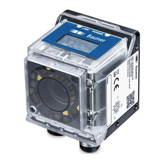
Page 10: Description
Sensor (filter recognition) Camera (with electromechanical focus) Internal illumination (each segment to be switched on individually) Electrical connection; 12-pin M12, A-en- 10 Ethernet connection (1 GigE); X-encoding coding 11 Protective plug (USB-C port without func- tion) Operating Manual VIXG | V1.0... -
Page 11: Led Status Indicator
Indicating the firmware version Indicating the camera type at boot up Indicating IP address Display will deactivate after having remained unchanged for 60 minutes. To reactivate, use a 3 mm wide screwdriver and the qTeach buttons. V1.0 | VIXG Operating Manual... -
Page 12: Camera Models
Sensor size Resolution Max. FPS (Width × Height) Monochrom VIXG-10M.W06 1/4″ 1280 × 800 VIXG-10M.W08 1/4″ 1280 × 800 Dimensional drawing M12 x 1 M12 x 1 15.45 30.65 14.5 35.5 Ill. 1: Dimensional drawing - VIXG Operating Manual VIXG | V1.0... -
Page 13: Transport And Storage
In case of externally visible transport damage, proceed as follows: Instruction: a) Do not accept the delivery or only with reservations. b) Note the scope of the damage on the transport documents or the delivery slip of the carrier. c) Initiate the claim. V1.0 | VIXG Operating Manual... -
Page 14: Installation
Heat accumulation in the device Heat can damage the device. Ensure adequate heat dissipation. In view of the varied installa- tion options Baumer does not make any recommendation for heat dissipation, but we suggest the following: a) Any form of convection around device and mounting helps reduce temperature. Prevent any heat accumulation! b) Mounting combined with forced convection may provide proper heat dissipation. -
Page 15: Mounting The Camera
Lateral mount Ill. 3: Screw-on points - lateral mount Condition: ð M3 screws × (5 + x) (3 pieces) / x = sheet thickness of screw-on angle w Screw on the camera. Tightening torque: max. 0.8 Nm. V1.0 | VIXG Operating Manual... -
Page 16: Accessories (Not Included)
Polarization filters may be used for improved inspection on glossy surfaces. Ill. 5: Snap-on polarization filter 44 mm (article number: 11704588) INFO Using a filter will darken the image. Re-parameterization of image acquisition configuration may be required. For more accessories visit our website at: https://www.baumer.com Operating Manual VIXG | V1.0... -
Page 17: Optical Specification
The values refer to the related data sheets. Cameras 1000 1100 ® ON Semiconductor AR0144CS mono Wave length [nm] Spectral sensitivity VIXG-10M.06 / VIXG-10M.08 Semuconductor® AR0144CS mono) V1.0 | VIXG Operating Manual... -
Page 18: Field Of View / Operating Distance
Below you see the minimum and maximum fields of view. Minimum VIXG-10M.06 VIXG-10M.08 50 mm 50 mm 41 mm x 25 mm 29 mm x 18 mm Maximum VIXG-10M.06 VIXG-10M.08 1000 mm 1000 mm 649 x 408 mm 485 mm x 303 mm Operating Manual VIXG | V1.0... - Page 19 550 x 344 500 x 313 450 x 281 400 x 250 350 x 219 300 x 188 250 x 156 200 x 125 150 x 94 100 x 63 50 x 31 1000 Working Distance (mm) V1.0 | VIXG Operating Manual...
-
Page 20: Depth Of Field
Optical specification Baumer Depth of field For information on device-specific depth of field (near / ideal / far) please see the following dia- grams. VIXG-10M.W.06 (focal length: 6 mm / aperture: 3.5) near ideal 1000 1200 1000 Opera•ng distance [mm] (from housing front edge) VIXG-10M.W.08 (focal length: 8 mm / aperture: 3.5) -
Page 21: Electrical Installation
Power supply always via the 12-pin M12 connector. Prerequisites for IP rating: ▪ Connection to power supply and network must be established by cable. ▪ Protective plug must be closed. The internal USB port has no function. V1.0 | VIXG Operating Manual... -
Page 22: Pin Assignment
PK – Pink YE – Yellow BK – Black GY – Gray RD – Red VT – Violet GY-PK – Gray Pink RD-BU – Red Blue Wire colors according to DIN IEC 757 -VDC -VDC +VDC +VDC Operating Manual VIXG | V1.0... -
Page 23: Wiring
Baumer Electrical installation Wiring Input Power + 18 ...+ 30 VDC IN 1 (Trigger) Output Power + 18 ...+ 30 VDC OUT 1 V1.0 | VIXG Operating Manual... -
Page 24: Maintenance
Never use a high-pressure cleaner for cleaning. d) Do not scrape off soiling with sharp-edged items. e) Only ever use a lens cloth for cleaning the front glass. Inside cleaning No interior cleaning required. Operating Manual VIXG | V1.0... -
Page 25: Troubleshooting
In case of any questions please contact our Technical & Application Support Center. Worldwide Baumer Optronic GmbH Badstrasse 30 DE - 01454 Radeberg www.baumer.com Tel.: +49 (0)3528 4386 845 support.cameras@baumer.com Accessories You can find accessories at the website at: www.baumer.com V1.0 | VIXG Operating Manual... -
Page 26: Software
Baumer Camera Explorer Easy-to-use Baumer Camera Explorer allows for camera evaluation and configuration within the least amount of time. It helps get to know and try the diversified functions of the Baumer cam- eras for configuration to the application. ®... -
Page 27: Genicam Camera Features
This chapter describes all features related to image acquisition, including the trigger and expo- sure control. 11.1.1 AcquisitionFrameRate Controls the acquisition rate (in Hertz) at which the frames are captured. Name AcquisitionFrameRate Category AcquisitionControl Interface IFloat Access Read / Write Unit Values depends on camera V1.0 | VIXG Operating Manual... -
Page 28: Acquisitionframerateenable
1. Determining the current set of image parameters 2. Sensor exposure 3. Readout from the sensor This process is then repeated until the camera is stopped. Name AcquisitionStart Category AcquisitionControl Interface ICommand Access Write only Unit Values Operating Manual VIXG | V1.0... -
Page 29: Acquisitionstop
Category AcquisitionControl Interface IEnumeration Access Read / Write Unit Values Timed Time-controlled exposure. The exposure duration time is set using the ExposureTime or ExposureAuto features and the ex- posure starts with the FrameStart or LineStart. V1.0 | VIXG Operating Manual... -
Page 30: Exposuretime
Camera type texposure min [μsec] texposure max [μsec] Monochrome VIXG-10M.W06 5000 VIXG-10M.W08 5000 11.1.9 TriggerActivation Specifies the trigger activation mode. Name TriggerActivation Category AcquisitionControl Interface IEnumeration Access Read / Write Unit Values see table(s) below Operating Manual VIXG | V1.0... -
Page 31: Triggerdelay
Disables selected Trigger. Enables selected Trigger. 11.1.12 TriggerSelector Selects the type of trigger to configure. Name TriggerSelector Category AcquisitionControl Interface IEnumeration Access Read / Write Unit Values Frame Start Selects the type of trigger to configure. V1.0 | VIXG Operating Manual... -
Page 32: Triggersoftware
BlackLevel Controls the analog black level as an absolute physical value. This represents a offset applied to the video signal. Name BlackLevel Category AnalogControl Interface IFloat Access Read / Write Unit Values see table(s) below Operating Manual VIXG | V1.0... -
Page 33: Blacklevelselector
Increasing the Gain will increase image noise. Name Gain Category AnalogControl Interface IFloat Access Read / Write Unit Values see table(s) below VIXG Camera type Gain Monochrome VIXG-10M.W06 1 ... 8 VIXG-10M.W08 1 ... 8 V1.0 | VIXG Operating Manual... -
Page 34: Gainauto
Selects which gain is controlled by the various gain feature. Name GainAuto Category AnalogControl Interface IEnumeration Access Read / Write Unit Values see table(s) below VIXG Values [GainSelector] All Gain values will be applied to all channels. Operating Manual VIXG | V1.0... -
Page 35: Category: Autofeaturecontrol
Example 2 For image 2, increasing bright- ness using Gain will not suffi- cient to achieve value in BrightnessAutoNominalValue. GainAutoMinValue GainAutoMaxValue Therefore, ExposureTime is in- BrightnessAutoPriority = Exposure creased once ExposureAu- toMaxValue has been achieved. V1.0 | VIXG Operating Manual... -
Page 36: Brightnessautopriority
Name BrightnessAutoPriority Category AutoFeatureControl Interface IEnumeration Access Read / Write Unit Values ExposureAuto ExposureAuto has highest priority and will be modified first. GainAuto GainAuto has highest priority and will be modified first. Operating Manual VIXG | V1.0... -
Page 37: Category: Devicecontrol
Access Read only Unit Values e.g. CID:000057/PID:11194280 11.4.3 DeviceLinkHeartbeatMode Activate or deactivate the Link`s heartbeat. Name DeviceLinkHeartbeatMode Category DeviceControl Interface IEnumeration Access Read / Write Unit Values Enables the Link heartbeat. Disables the Link heartbeat. V1.0 | VIXG Operating Manual... -
Page 38: Devicelinkheartbeattimeout
Interface IInteger Access Read / Write Unit Values ≥ 0 11.4.6 DeviceLinkSpeed Indicates the speed of transmission negotiated on the specified link. Name DeviceLinkSpeed Category DeviceControl Interface IInteger Access Read only Unit Values ≥ 0 Operating Manual VIXG | V1.0... -
Page 39: Devicelinkthroughputlimit
DeviceManufacturerInfo Category DeviceControl Interface IString Access Read only Unit Values e.g.F:00007F9A/C:0180802D/BL3.8:00000081 INFO The following information is available for VIXG: BN:XXXXXX/L:X.X.X-XX (BuildNr = Jenkins Build, L = Linux-Version) 11.4.9 DeviceModelName Model name of the device. Name DeviceModelName Category DeviceControl Interface IString... -
Page 40: Deviceperipheralenable
Values StatusLED Aimer Display 11.4.12 DeviceReset Resets the device to its power up state. INFO The execution of this feature may take several seconds. Name DeviceReset Category DeviceControl Interface IComand Access Write only Unit Values Operating Manual VIXG | V1.0... -
Page 41: Deviceserialnumber
0 ... 9223372036854775807 (Increment: 1) 11.4.16 DeviceSFNCVersionSubMinor Sub version of Standard Features Naming Convention, used to create the device GenICam XML(x.x.X). Name DeviceSFNCVersionSubMinor Category DeviceControl Interface IInteger Access Read only Unit Values 0 ... 9223372036854775807 (Increment: 1) V1.0 | VIXG Operating Manual... -
Page 42: Devicestreamchannelpacketsize
IEnumeration Access Read / Write Unit Values InHouse Temperature inside the camera housing. 11.4.20 DeviceVendorName Name of the manufacturer of the device. Name DeviceVendorName Category DeviceControl Interface IString Access Read only Unit Values Manufacturer name. Operating Manual VIXG | V1.0... -
Page 43: Deviceversion
Different trigger sources can be used here. 30 V start active Trigger high 11 V 4.5 V delay Trigger A Trigger delay Trigger (valid) B Exposure time C Readout time Exposure Readout Time V1.0 | VIXG Operating Manual... - Page 44 Different objects can be captured without hardware changes Trigger Source (examples of possible trigger sources) Each trigger source must be activated separately. When the trigger mode (TriggerMode) is acti- vated, the hardware trigger is activated by default. Operating Manual VIXG | V1.0...
-
Page 45: Lineinverter
Selects the physical line (or pin) of the external device connector to configure. Name LineSelector Category DigitalIOControl Interface IInteger Access Read / Write Unit Values see table(s) below VIXG Values [Lineselector] Line0 (IN1) Line1 (IN2) Line2 (IN3) Line3 (OUT1) Line4 (OUT2) Line5 (OUT3) V1.0 | VIXG Operating Manual... -
Page 46: Linesource
= 0 (Off) 11.5.6 LineStatusAll Returns the current status of all available Line signals at time of polling in a single bitfield. Name LineStatusAll Category DigitalIOControl Interface IInteger Access Read only Unit Values Devices-Specific (HexNumber) Operating Manual VIXG | V1.0... -
Page 47: Category: Fileaccesscontrol
Category including the functions for file access control. NOTICE Updating incorrect firmware may cause the camera becoming unusable We recommend using Baumer Update Tool for camera firmware updates. Only update the most recently authorized firmware version. If required, contact customer support before updating the firmware. -
Page 48: Fileopenmode
Unit Values 11.6.6 FileOperationResult Indicates the file operation result. Read or write operations return the number of bytes success- fully read/written. Name FileOperationResult Category FileAccessControl Interface IInteger Access Read only Unit Byte Values ≥ 0 Operating Manual VIXG | V1.0... -
Page 49: Fileoperationselector
Success File operation successful. Failure File operation failed. 11.6.9 FileSelector Feature FileSelector can be used to select a specific file of the camera. Name FileSelector Category FileAccessControl Interface IEnumeration Access Read / Write Unit Values V1.0 | VIXG Operating Manual... -
Page 50: Filesize
Start ROI End ROI Name Height Category ImageFormatControl Interface IInteger Access Read / Write Unit Values see table(s) below Camera type Values [Pixel] Monochrome VIXG-10M.W06 1 … 800 (Increment: 1) VIXG-10M.W08 1 … 800 (Increment: 1) Operating Manual VIXG | V1.0... -
Page 51: Heightmax
- even if data do not completely fill the second byte. 8 bit 8 bit sequence Byte 1 INFO The camera must be stopped before this feature can be edited. Name PixelFormat Category ImageFormatControl Interface IEnumeration Access Read / Write Unit Values see table(s) below V1.0 | VIXG Operating Manual... -
Page 52: Sensorheight
0.000000 ... 255.000000 (Increment: 1) 11.7.7 SensorPixelWidth Physical size (pitch) in the x direction of a photo sensitive pixel unit. Name SensorPixelWidth Category ImageFormatControl Interface IFloat Access Read only Unit µm Values 0.000000 ... 255.000000 (Increment: 1) Operating Manual VIXG | V1.0... -
Page 53: Sensorshuttermode
0 ... 65535 (Increment: 1) 11.7.10 Width Width of the image provided by the device (in pixels). Start ROI End ROI Name Width Category ImageFormatControl Interface IInteger Access Read / Write Unit Values see table(s) below V1.0 | VIXG Operating Manual... -
Page 54: Widthmax
Here is enabling / disabling of the internal lighting segments. Image brightness control is via the feature ExposureTime. Name LightBrightness Category LightControl Interface IFloat Access Read / Write Unit Values 0 ... 100 (Increment: 100) Operating Manual VIXG | V1.0... -
Page 55: Lightcontrollerselector
11.9 Category: OpticControl Category including the optics control features (e.g. lens). 11.9.1 FocalLength Focal length in millimeters. Name FocalLength Category OpticControl Interface IFloat Access Read / Write Unit Values > 0 (according to optical system) V1.0 | VIXG Operating Manual... -
Page 56: Focusauto
Select optical controller to be configured. Name OpticControllerSelector Category OpticControl Interface IEnumeration Access Read / Write Unit Values e.g.OpticController 0 11.9.5 OpticControllerVendorName Manufacturer name of optical controller. Name OpticControllerVendorName Category OpticControl Interface IString Access Read only Unit Values Name Operating Manual VIXG | V1.0... -
Page 57: Category: Transportlayercontrol
Interface IInteger Access Read only Unit Values IP address 11.10.1.3 GevCurrentIPAddress Reports the IP address for the given logical link. Name GevCurrentIPAddress Category TansportLayerControl → GigEVision Interface IInteger Access Read only Unit Values IP address V1.0 | VIXG Operating Manual... -
Page 58: Gevcurrentipconfigurationdhcp
Values true = 1 (On) false = 0 (Off) 11.10.1.7 GevCurrentSubnetMask Reports the subnet mask of the given logical link. Name GevCurrentSubnetMask Category TansportLayerControl → GigEVision Interface IInteger Access Read only Unit Values IP address Operating Manual VIXG | V1.0... -
Page 59: Gevpersistentdefaultgateway
IInteger Access Read / Write Unit Values ≥ 0 11.10.1.11 GevInterfaceSelector Selects which logical link to control. Name GevInterfaceSelector Category TansportLayerControl → GigEVision Interface IInteger Access Read / Write Unit Values ≥ 0 (Increment: 1) V1.0 | VIXG Operating Manual... -
Page 60: Gevipconfigurationstatus
Specifies the stream packet size, in bytes, to send on the selected channel for a GVSP trans- mitter or specifies the maximum packet size supported by a GVSP receiver. Name GevSCPSPacketSize Category TansportLayerControl → GigEVision Interface IInteger Access Read / Write Unit Byte Values > 0 (Increment: 2) Operating Manual VIXG | V1.0... -
Page 61: Payloadsize
Provides the number of bytes transferred for every image or Chunk on the Stream Channel with current parameterization. Total size of data payload for a data block. Name PayloadSize Category TansportLayerControl Interface IInteger Access Read only Unit Byte Values 0 ... depends on current parameterization (Increment: 1) V1.0 | VIXG Operating Manual... -
Page 62: Gige Interface Functionality
When starting image transfer at a camera, data packets are transferred with maximum transfer speed. In compliance with the network standard, Baumer cameras operate on a 12-byte mini- mum distance between every packet. This gap is referred to as Inter Packet Gap (IPG). Further ®... - Page 63 This way, both data packets can be transmitted one after another other (zipper method) without the need for buffering by switch. The IPG is mapped in the camera using the GevSCPD function. Observe the specified unit. Conversion may be required. V1.0 | VIXG Operating Manual...
-
Page 64: Frame Transmission Delay
Time savings in multi-camera operation As already mentioned, feature Frame Transmission Delay is particularly intended for multi-cam- era operation and using different camera models. This would particularly speed up image trans- mission of individual cameras: Operating Manual VIXG | V1.0... - Page 65 Transfer time (ttransferGigE) is calculated as follows: Transmission time = Resulting data volume / (1000 × 1000) [ms] All cameras are triggered simultaneously. Transmission delay is implemented in the form of a counter which runs immediately when start- ing sensor readout. V1.0 | VIXG Operating Manual...
- Page 66 ∑ − Transmissi onDelay Camera osure Camera readout Camera osure Camera transferGi Camera − ≥ Transmission delays of camera 2 and 3 are calculated as follows: tTransmissionDelay (Camera 2) texposure(Camera 1) treadout(Camera 1) texposure(Camera 2) Operating Manual VIXG | V1.0...
-
Page 67: Multicast
In the below example illustration, multicast is used for separate processing of image and mes- sage data at two individual PCs. INFO For multicasting, Baumer suggests an address range from 232.0.1.0 to 232.255.255.255. V1.0 | VIXG Operating Manual... -
Page 68: Ip-Konfiguration
IP address or the process will repeat. ® This may take some time - the GigE Vision standard specifies that establishing connection via LLA should not take longer than 40 seconds, worst case it can take up to several minutes. Operating Manual VIXG | V1.0... -
Page 69: Force Ip (Static Ip)
In this case,Force IP (Static IP) may present a final solution. The Force IP feature will transmit IP address and subnet mask to the camera's MAC address. These settings are sent without ver- ification and immediately applied by the client. They remain valid until camera power off. V1.0 | VIXG Operating Manual... -
Page 70: List Of Illustrations
List of illustrations Baumer List of illustrations Ill. 1 Dimensional drawing - VIXG ....................... 12 Ill. 2 Screwing points - rear mount ......................15 Ill. 3 Screw-on points - lateral mount ......................15 Ill. 4 Smart Mounting Kit A .......................... 16 Ill.
Need help?
Do you have a question about the VIXG and is the answer not in the manual?
Questions and answers