
Related Manuals for Baumer EXG


Summary of Contents for Baumer EXG
- Page 1 User´s Guide EXG (Gigabit Ethernet) Document Version: v1.1 Release: 21.06.2017 Document Number: 11037992...
-
Page 3: Table Of Contents
2.3.3 LED Signaling ��������������������������������������������������������������������������������������������������11 2.4 Environmental Requirements �������������������������������������������������������������������������������� 12 2.4.1 Temperature and Humidity Range ������������������������������������������������������������������ 12 2.4.2 Heat Transmission ������������������������������������������������������������������������������������������ 12 3. Software ........................13 3.1 Baumer-GAPI �������������������������������������������������������������������������������������������������������� 13 3�2 3 Party Software �������������������������������������������������������������������������������������������������� 13 4. Camera Functionalities ..................14 4.1 Image Acquisition �������������������������������������������������������������������������������������������������� 14 4.1.1 Image Format ������������������������������������������������������������������������������������������������� 14 4.1.2 ... - Page 4 4.6.6 Frame Counter ����������������������������������������������������������������������������������������������� 25 4.7 User Sets �������������������������������������������������������������������������������������������������������������� 26 4.8 Factory Settings ���������������������������������������������������������������������������������������������������� 26 4.9 Timestamp ������������������������������������������������������������������������������������������������������������ 26 5. Interface Functionalities ..................27 5.1 Device Information ������������������������������������������������������������������������������������������������ 27 5.2 Packet Size and Maximum Transmission Unit (MTU) ������������������������������������������� 27 5.3 Inter Packet Gap ��������������������������������������������������������������������������������������������������� 27 5.3.1 Example 1: Multi Camera Operation – Minimal IPG ��������������������������������������� 28 5.3.2 Example 2: Multi Camera Operation – Optimal IPG ��������������������������������������� 28 5.4 ...
-
Page 5: Camera Models
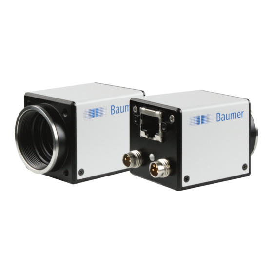
1. Camera Models ◄ Figure 1 Front and rear view of a Baumer EXG camera. Full Sensor Camera Type Resolution Frames Size [max. fps] Monochrome EXG03 1/3" 752 x 480 EXG50 1/2.5" 2592 x 1944 Color EXG03c 1/3" 748 x 476 EXG50c 1/2.5" 2592 x 1944 Dimensions Photosensitive C-Mount surface of the sensor ◄ Figure 2... -
Page 6: Product Specifications
2. Product Specifications 2.1 Sensor Specifications 2.1.0.1 Quantum Efficiency for Baumer EXG Cameras The quantum efficiency characteristics of monochrome and color matrix sensors for Baumer EXG cameras are displayed in the following graphs. The characteristic curves for the sensors do not take the characteristics of lenses and light sources without filters into consideration. Values relating to the respective technical data sheets of the sensors manufacturer. Figure 3 ► Spectral sensitivities for Baumer EXG cameras with 0.3 MP CMOS sensor� 1050 1150 1050 1150 EXG03c Wave Length [nm] EXG03 Wave Length [nm] *) MP = Megapixels Figure 4 ►... - Page 7 Readout Pointer Pixels of Frame – will be deleted (n-1) ◄ Figure 6 Currently exposed pixels (Frame Operating mode of a Read out pixels of current Frame (Frame rolling shutter. Rolling shutter means that – in contrast to the global shutter – not the whole sensor is exposed at once, but single portions successively. It is said the shutter "rolls" over the sensor� For Baumer EXG cameras with rolling shutter this means two pointers are "rolling" across the sensor: ▪ First, the reset pointer deletes any information of former exposures stored within the pixels (Frame ). After that the pixels are empty and restart collecting information (n-1) from incoming light – the new exposure (Frame ) begins. ▪ Once a predefined interval – the exposure time t – is elapsed, the readout exposure pointer rolls across the sensor and the information of the pixels is read out.
-
Page 8: 2�2 Timings
Non-overlapped Operation Overlapped Operation Here the time intervals are long enough In this operation the exposure of a frame to process exposure and readout succes- (n+1) takes place during the readout of sively. frame (n). Exposure Exposure Readout Readout Due to the differing CMOS sensor models installed to the Baumer EXG cameras, the operation modes are subdevided into the respective camera models. 2.2.1 Free Running Mode In the "Free Running" mode the camera records images permanently and sends them to the PC. In order to achieve an optimal (with regard to the adjusted exposure time t exposure and image format) the camera is operated overlapped. In case of exposure times equal to / less than the readout time (t ≤ t ), the maxi- exposure readout mum frame rate is provided for the image format used. For longer exposure times the ... -
Page 9: 2�2�2 Trigger Mode
2.2.1.2 EXG50 Sensor Full Frame Reset exposure(n) exposure(n+1) delay Sensor Full Frame Readout Timing Value 71�66 msec Full Frame 4 µsec ��� 1 sec exposure 2.2.2 Trigger Mode After a specified external event (trigger) has occurred, image acquisition is started. 2.2.2.1 EXG03 / EXG03c Trigger triggerdelay exposure(n) exposure(n+1) Exposure readout(n) readout(n+1) Readout notready TriggerReady flash(n+1) flash(n) Flash flashdelay... - Page 10 2.2.2.2 EXG50 Timings: A - exposure time frame (n) effective B - image parameters frame (n) effective Trigger triggerdelay Sensor Full Frame Reset exposure Image parameters: Sensor Offset Full Frame Gain Readout Mode Partial Scan delay...
-
Page 11: Process- And Data Interface
(og) MX2- (bn/wh) MX4+ (bn) MX4- 2.3.2 Pin-Assignment Power Supply and Digital IOs M8 / 3 pins M8 / 4 pins (bn) Power V (bn) TrigIN+ (bu) (wh) TrigIN- (bk) (bu) Flash (bk) 2.3.3 LED Signaling ◄ Figure 7 LED positions on Baumer EXG cameras. Signal Meaning green Power on yellow Readout active green Link active green flash Receiving yellow Transmitting yellow / red flash Receiving and Transmitting... -
Page 12: Environmental Requirements
Value A Value B Monochrome EXG03 +25°C (+77°F) +50°C (+122°F) EXG50 +25°C (+77°F) +50°C (+122°F) Color EXG03c +25°C (+77°F) +50°C (+122°F) Humidity Storage and Operating Humidity 10% ��� 90% Non-condensing Figure 8 ► Temperature measure- ment points of Baumer EXG cameras 2.4.2 Heat Transmission It is very important to provide adequate dissipation of heat, to ensure that the temperature does not reach or exceed +50°C (+122°F). As there are numerous possibilities for instal- lation, Baumer do not specifiy a specific method for proper heat dissipation, but suggest the following principles: ▪ operate the cameras only in mounted condition ▪ mounting in combination with forced convection may provide proper heat dissipation *) Please refer to the respective data sheet. **) Measured at temperature measurement point (T). ***) Housing temperature is limited by sensor specifications. -
Page 13: Software
3. Software 3.1 Baumer-GAPI Baumer-GAPI stands for Baumer “Generic Application Programming Interface”. With this API Baumer provides an interface for optimal integration and control of Baumer Gigabit Ethernet (GigE) and Baumer FireWire™ (IEEE1394) cameras. This software interface allows changing to other camera models or interfaces. It also al- lows the simultaneous operation of Baumer cameras with Gigabit Ethernet and FireWire™ interfaces. This GAPI supports both Windows (XP and Vista) and Linux (from Kernel 2.6.x) operat- ® ® ing systems in 32 bit, as well as in 64 bit. It provides interfaces to several programming languages, such as C, C++ and the .NET™ Framework on Windows , as well as Mono ® on Linux operating systems, which offers the use of other languages, such as e.g. C# or ® VB.NET. 3.2 3 Party Software Strict compliance with the Gen<I>Cam™ standard allows Baumer to offer the use of 3 Party Software for operation with cameras of the EXG series. You can find a current listing of 3 Party Software, which was tested successfully in com- bination with Baumer cameras, at http://www.baumer.com�... -
Page 14: Camera Functionalities
4. Camera Functionalities 4.1 Image Acquisition 4.1.1 Image Format A digital camera usually delivers image data in at least one format - the native resolution of the sensor. Baumer cameras are able to provide several image formats (depending on the type of camera). Compared with standard cameras, the image format on Baumer cameras not only in- cludes resolution, but a set of predefined parameter. These parameters are: ▪ Resolution (horizontal and vertical dimensions in pixels) ▪ Binning Mode(see chapter 4.1.6) Camera Type Monochrome EXG03 ■ ■ ■ ■ □ EXG50 ■ □... -
Page 15: Pixel Format
4.1.2 Pixel Format On Baumer digital cameras the pixel format depends on the selected image format. 4.1.2.1 Definitions RAW: Raw data format. Here the data are stored without processing. Bayer: Raw data format of color sensors. Color filters are placed on these sensors in a checkerboard pattern, generally in a 50% green, 25% red and 25% blue array. ◄ Figure 9 Sensor with Bayer Pattern Mono: Monochrome. The color range of mono images consists of shades of a single color. In general, shades of gray or black-and-white are synonyms for mono- chrome� RGB: Color model, in which all detectable colors are defined by three coordinates, Red, Green and Blue. White Black ◄ Figure 10 Green RBG color space dis- Blue played as color tube. The three coordinates are displayed within the buffer in the order R, G, B. ... - Page 16 Byte 2 Packed: Figure 14 ► Pixel 0 Pixel 1 Spreading of two pix- els in Mono 12 bit over three bytes (packed Byte 1 Byte 2 Byte 3 mode). 4.1.2.2 Pixel Formats on Baumer EXG Cameras Camera Type Monochrome EXG03 ■ ■ ■ □ □ □ □ □...
-
Page 17: Exposure Time
The signal strength is influenced by the incoming amount of photons. It can be increased by increasing the exposure time (t exposure On Baumer EXG cameras, the exposure time can be set within the following ranges (step size 1μsec): Auto Exposure: Camera Type min max Some models of the EXG exposure exposure series are equipped with Monochrome the ability for automatic EXG03 32 μsec 1 sec adjustment of the exposure EXG50 4 μsec... -
Page 18: Partial Scan / Area Of Interest (Aoi)
On Baumer EXG cameras the correction factor γ is adjustable from 0.001 to 2. The values of the calculated intensities are entered into the Look-Up-Table (see 4.1.4.). Thereby previously existing values within the LUT will be overwritten. Notice If the LUT feature is disabled on the software side, the gamma correction feature also is disabled. 4.1.7 Partial Scan / Area of Interest (AOI) With the "Partial Scan" function it is possible to predefine a so-called Area / Region of Interest (AOI / ROI). This ROI is an area of pixels of the sensor. On image acquisition, only the information of these pixels is sent to the PC. Therefore all the lines of the sensor need not be read out, which decreases the readout time (t ). This increases the frame readout rate. This function is employed, when only a region of the field of view is of interest. It is coupled to a reduction in resolution. The ROI is specified by four values: ▪ Offset X - x-coordinate of the first relevant pixel ▪ Offset Y - y-coordinate of the first relevant pixel ▪ Size X - horizontal size of the ROI ▪ Size Y - vertical size of the ROI Start ROI End ROI Figure 17 ► Partial Scan: Parameters of the ROI. -
Page 19: 4�1�8 Binning
4.1.8 Binning On digital cameras, you can find several operations for progressing sensitivity. One of them is the so-called "Binning". Here, the charge carriers of neighboring pixels are aggre- gated. Thus, the progression is greatly increased by the amount of binned pixels. By using this operation, the progression in sensitivity is coupled to a reduction in resolution. Baumer cameras support three types of Binning - vertical, horizontal and bidirectional. In unidirectional binning, vertically or horizontally neighboring pixels are aggregated and reported to the software as one single "superpixel". In bidirectional binning, a square of neighboring pixels is aggregated. Binning Illustration Example without ◄ Figure 18 Full frame image, no binning of pixels. ◄ Figure 19 Vertical binning causes a vertically compressed image with doubled ... -
Page 20: Brightness Correction (Binning Correction)
4.2 Color Processing Baumer color cameras are balanced to a color temperature of 5000 K. Oversimplified, color processing is realized by 4 modules. Color- Camera Bayer Transfor- Module Processor mation Figure 24 ► Color processing mod- ules of Baumer color White balance cameras. The color signals r (red), g (green) and b (blue) of the sensor are amplified in total and digitized within the camera module. Within the Bayer processor, the raw signals r', g' and b' are amplified by using of indepen- dent factors for each color channel. Then the missing color values are interpolated, which results in new color values (r'', g'', b''). The luminance signal Y is also generated. The next step is the color transformation. Here the previously generated color signals r'', g'' and b'' are converted to the chroma signals U and V, which conform to the standard. Afterwards theses signals are transformed into the desired output format. Thereby the following steps are processed simultaneously: ▪... -
Page 21: User-Specific Color Adjustment
Color EXG03c 10 bit 4.4.2 Gain In industrial environments motion blur is unacceptable. Due to this fact exposure times are limited. However, this causes low output signals from the camera and results in dark Auto Gain: images. To solve this issue, the signals can be amplified by a user-defined gain factor Some models of the EXG within the camera. This gain factor is adjustable from 1 to 10. series are equipped with the ability for automatic ad- Notice justment of the gain factor by means of target-settings Increasing the gain factor causes an increase of image noise. -
Page 22: Pixel Correction
„Cold Pixel“ Figure 28 ► Charge quantity of "hot" and "cold" pixels com- pared with "normal" pixels. 4.5.2 Correction Algorithm On monochrome cameras of the Baumer EXG series, the problem of defect pixels is solved as follows: ▪ Possible defect pixels are identified during the production process of the camera. ▪ The coordinates of these pixels are stored in the factory settings of the camera (see 4�5�3� Defectpixellist). ▪ Once the sensor readout is completed, correction takes place: ▪ Before any other processing, the values of the two neighboring pixels on the left and the right side of the defect pixel, will be read out ▪... -
Page 23: Defectpixellist
4.5.3 Defectpixellist As stated previously, this list is determined within the production process of Baumer cam- eras and stored in the factory settings (see 4.8.1.). Additional hot or cold pixels can develop during the lifecycle of a camera. In this case Baumer offers the possibility of adding their coordinates to the defectpixellist. The user can determine the coordinates of the affected pixels and add them to the list. Once the defect pixel list is stored in a user set (see 4.8.), pixel correction is executed for all coor- dinates on the defectpixellist. 4.6 Process Interface 4.6.1 IO Circuits Output high active Output low active Input Camera Customer Device Camera Customer Device Customer Device Camera IO Power V CC IO Power V CC I OUT I OUT IO GND... -
Page 24: Trigger Input
4.6.2 Trigger Input Trigger signals are used to synchronize the camera exposure and a machine cycle or, in case of a software trigger, to take images at predefined time intervals� high Trigger (valid) 4.5V Figure 30 ▲ Trigger signal, valid for Exposure Baumer cameras. Figure 31 ► Camera in trigger mode: Readout A - Trigger delay B - Exposure time (global shutter) Different trigger sources can be used here� B*- Exposure time (rolling shutter) 4.6.3 Trigger Source C - Readout time Trigger Delay: The trigger delay is a flexible user-defined delay... -
Page 25: Debouncer
4.5V - high time of the signal - user-defined debouncer delay for state high ◄ Figure 33 DebounceHigh - user-defined debouncer delay for state low Principle of the Baumer DebounceLow debouncer. 4.6.5 Flash Signal This signal is managed by exposure of the sensor. Furthermore, the falling edge of the flash output signal can be used to trigger a movement of the inspected objects. Due to this fact, the span time used for the sensor readout t readout can be used optimally in industrial environments. 4.6.6 Frame Counter The frame counter is part of the Baumer image infoheader and supplied with every image, if the chunkmode is activated. It is generated by hardware and can be used to verify that every image of the camera is transmitted to the PC and received in the right order. -
Page 26: User Sets
4.7 User Sets Four user sets (0-3) are available for the Baumer cameras of the EXG series. User set 0 is the default set and contains the factory settings. User sets 1 to 3 are user-specific and can contain the following information: Parameter Parameter Binning Image Format Brightness Correction Look-Up-Table Defect Pixel Correction Message Channel Defectpixellist Offset (Black Level) Flash Settings Partial Scan Gain Pixel Format Flash Settings Trigger Settings These user sets are stored within the camera and and cannot be saved outside the de- vice. By employing a so-called "user set default selector", one of the four possible user sets can be selected as default, which means, the camera starts up with these adjusted pa- rameters. 4.8 Factory Settings The factory settings are stored in "user set 0" which is the default user set. This is the only user set, that is not editable. 4.9 Timestamp The timestamp is part of the GigE Vision ... -
Page 27: Interface Functionalities
The packet size of UDP packets can differ from 576 Bytes up to the MTU. The MTU describes the maximal packet size which can be handled by all network com- ponents involved. In principle modern network hardware supports a packet size of 1500 Byte, which is specified in the network standard. However, so-called "Jumboframes" are on the advance as Gigabit Ethernet continues to spread. "Jumboframes" merely characterizes a packet size exceeding 1500 Bytes. Baumer EXG cameras can handle a MTU of up to 65535 Bytes. 5.3 Inter Packet Gap To achieve optimal results in image transfer, several Ethernet-specific factors need to be IPG: considered when using Baumer EXG cameras. The IPG is measured in ticks (described in chapter Upon starting the image transfer of a camera, the data packets are transferred at maxi- 5.2). mum transfer speed (1 Gbit/sec). In accordance with the network standard, Baumer em-... -
Page 28: Example 1: Multi Camera Operation - Minimal Ipg
5.3.1 Example 1: Multi Camera Operation – Minimal IPG Setting the IPG to minimum means every image is transfered at maximum speed. Even by using a frame rate of 1 fps this results in full load on the network. Such "bursts" can lead to an overload of several network components and a loss of packets. This can occur, especially when using several cameras. In the case of two cameras sending images at the same time, this would theoretically oc- Figure 35 ▲ cur at a transfer rate of 2 Gbits/sec. The switch has to buffer this data and transfer it at a Operation of two camer- as employing a Gigabit speed of 1 Gbit/sec afterwards. Depending on the internal buffer of the switch, this oper- Ethernet switch. ates without any problems up to n cameras (n ≥ 1). More cameras would lead to a loss of Data processing within packets. These lost packets can however be saved by employing an appropriate resend the switch is displayed mechanism, but this leads to additional load on the network components� in the next two figures. Figure 36 ► Operation of two cam- eras employing a minimal inter packet (IPG). 5.3.2 Example 2: Multi Camera Operation – Optimal IPG A better method is to increase the IPG to a size of optimal IPG = packet size + 2 × minimal IPG In this way both data packets can be transferred successively (zipper principle), and the ... -
Page 29: Ip Configuration
Please ensure a valid combination of IP address and subnet mask. IP range: Subnet mask: 0.0.0.0 – 127.255.255.255 255�0�0�0 128.0.0.0 – 191.255.255.255 255�255�0�0 192.0.0.0 – 223.255.255.255 255�255�255�0 ▲ Figure 38 These combinations are not checked by Baumer GAPI, Baumer GAPI Viewer or camera Connection pathway for on the fly. This check is performed when restarting the camera, in case of an invalid IP Baumer Gigabit Ether- net cameras: - subnet combination the camera will start in LLA mode� The device connects * This feature is disabled by default� step by step via the three described mecha- nisms� 5.4.2 DHCP (Dynamic Host Configuration Protocol) The DHCP automates the assignment of network parameters such as IP addresses, sub- net masks and gateways. This process takes up to 12 sec. Once the device (client) is connected to a DHCP-enabled network, four steps are processed: ▪ DHCP Discovery In order to find a DHCP server, the client sends a so called DHCPDISCOVER broad- cast to the network. -
Page 30: 5�4�3 Lla
▪ DHCP Request Once the client has received this DHCPOFFER, the transaction needs to be con- firmed. For this purpose the client sends a so called DHCPREQUEST broadcast to the network. This message contains the IP address of the offering DHCP server and informs all other possible DHCPservers that the client has obtained all the necessary information, and there is therefore no need to issue IP information to the client. Figure 41 ► DHCP Request (broadcast) ▪ DHCP Acknowledgement Once the DHCP server obtains the DHCPREQUEST, a unicast containing all neces- sary information is sent to the client. This message is called DHCPACK. According to this information, the client will configure its IP parameters and the pro- cess is complete. DHCP Lease Time: The validity of DHCP IP addresses is limited by the lease time. When this time is elapsed, the IP configu- ration needs to be redone. This causes a connection abort. -
Page 31: Packet Resend
5.5 Packet Resend Due to the fact, that the GigE Vision standard stipulates using a UDP - a stateless user ® datagram protocol - for data transfer, a mechanism for saving the "lost" data needs to be employed. Here, a resend request is initiated if one or more packets are damaged during transfer and - due to an incorrect checksum - rejected afterwards. On this topic one must distinguish between three cases: 5.5.1 Normal Case In the case of unproblematic data transfer, all packets are transferred in their correct order from the camera to the PC. The probability of this happening is more then 99%� ◄ Figure 43 Data stream without damaged or lost pack- ets. 5.5.2 Fault 1: Lost Packet within Data Stream If one or more packets are lost within the data stream, this is detected by the fact, that packet number n is not followed by packet number (n+1). In this case the application sends a resend request (A). Following this request, the camera sends the next packet and ... -
Page 32: Termination Conditions
Figure 45 ► Resending of lost pack- ets at the end of the data stream. In our example, packets from no. 3 to no. 5 are lost. This fault is detected after the predefined time has elapsed and the resend request (A) is triggered. The camera then resends packets no. 3 to no. 5 (B) to complete the image transfer. 5.5.4 Termination Conditions The resend mechanism will continue until: ▪ all packets have reached the pc ▪ the maximum of resend repetitions is reached ▪ the resend timeout has occured or ▪... -
Page 33: Message Channel
Line1Falling Falling edge detected on IO-Line 1 Line2Rising Rising edge detected on IO-Line 2 Line2Falling Falling edge detected on IO-Line 2 Line3Rising Rising edge detected on IO-Line 3 Line3Falling Falling edge detected on IO-Line 3 Line4Rising Rising edge detected on IO-Line 4 Line4Falling Falling edge detected on IO-Line 4 Line5Rising Rising edge detected on IO-Line 5 Line5Falling Falling edge detected on IO-Line 5 Vendor-specific EventError Error in event handling EventLost Occured event not analyzed TemperatureExceeded Reference value of temperature exceeded TriggerReady (see chapter 2.4) elapsed, camera is able to notready process incoming trigger TriggerOverlapped Overlapped Mode (see chapter 2.4) detected TriggerSkipped Camera overtriggered (see chapter 2.4) Notice By the individual cameras of the Baumer EXG series the GigE Vision Message Chan- ® nel is supported in different degrees. -
Page 34: Action Command / Trigger Over Ethernet
5.7 Action Command / Trigger over Ethernet The basic idea behind this feature was to achieve a simultaneous trigger for multiple cameras. Therefore a broadcast ethernet packet was implemented. This packet can be used to induce a trigger as well as other actions. Due to the fact that different network components feature different latencies and jitters, the trigger over the Ethernet is not as synchronous as a hardware trigger. Nevertheless, applications can deal with these jitters in switched networks, and therefore this is a com- fortable method for synchronizing cameras with software additions. The action command is sent as a broadcast. In addition it is possible to group cameras, so that not all attached cameras respond to a broadcast action command. Such an action command contains: ▪ a Device Key - for authorization of the action on this device ▪... -
Page 35: Start-Stop-Behaviour
If the interface is stopped during a transmission, this is aborted immediately. 6.3 Pause / Resume Interface Pausing while the interface is operational, results in an interim storage of the recorded images within the internal buffer of the camera. After resuming the interface, the buffered image data will be transferred to the PC. 6.4 Acquisition Modes In general, three acquisition modes are available for the cameras in the Baumer EXG series� 6.4.1 Free Running Free running means the camera records images continuously without external events. 6.4.2 Trigger The basic idea behind the trigger mode is the synchronization of cameras with machine cycles. Trigger mode means that image recording is not continuous, but triggered by ... -
Page 36: Notes And Instructions
Notice Keep camera housing closed. There are no adjustable parts inside the camera! In order to avoid the loss of warranty do not open the housing! Notice Dismantling / Rework / Repair of Baumer Cameras If it is obvious that the device is / was dismantled, reworked or repaired by other than Baumer technicians, Baumer Optronic will not take any responsibility for the subse- quent performance and quality of the device! 7.2 Lens Mounting Notice Avoid contamination of the sensor and the lens by dust and airborne particles when mounting the lens to the device! Therefore the following points are very important: ▪ Install the camera in an environment that is as dust free as possible! ▪... -
Page 37: Conformity
8. Conformity Cameras of the Baumer EXG family comply with: ▪ CE, ▪ FCC Part 15 Class B, ▪ RoHS ▪ KC 8.1 CE We declare, under our sole responsibility, that the previously described Baumer EXG cameras conform with the directives of the CE. 8.2 FCC – Class B Device : This equipment has been tested and found to comply with the limits for a Class B digital device, pursuant to part 15 of the FCC Rules. These limits are designed to pro- vide reasonable protection against harmful interference in a residential environment. This equipment generates, uses, and can radiate radio frequency energy and, if not installed and used in accordance with the instructios, may cause harmful interference to radio ... -
Page 38: Index
12 bit ������������������������������������������������������������������������������������������������������������������������������������������������ 16, 21 Acquisition ���������������������������������������������������������������������������������������������������������������������������������� 14, 33, 35 Action Command ������������������������������������������������������������������������������������������������������������������������������������ 34 Analog Controls �������������������������������������������������������������������������������������������������������������������������������������� 21 AOI ��������������������������������������������������������������������������������������������������������������������������������������������������������� 18 Area of Interest ��������������������������������������������������������������������������������������������������������������������������������������� 18 Asynchronous Reset ������������������������������������������������������������������������������������������������������������������������������ 35 Baumer-GAPI ����������������������������������������������������������������������������������������������������������������������������������� 13, 29 Bayer ������������������������������������������������������������������������������������������������������������������������������������������ 15, 16, 20 Bayer RG 8 �������������������������������������������������������������������������������������������������������������������������������������������� 16 Bayer RG 10 ������������������������������������������������������������������������������������������������������������������������������������������ 16 Bayer RG 12 ������������������������������������������������������������������������������������������������������������������������������������������ 16 BGR ������������������������������������������������������������������������������������������������������������������������������������������������� 15, 16 BGR 8 Packed ��������������������������������������������������������������������������������������������������������������������������������������� 16 Binning ���������������������������������������������������������������������������������������������������������������������������������... - Page 39 FrameStart ��������������������������������������������������������������������������������������������������������������������������������������������� 33 Free Running Mode ��������������������������������������������������������������������������������������������������������������������������������� 8 Full frame ����������������������������������������������������������������������������������������������������������������������������������������� 14, 19 Full frame HQ ����������������������������������������������������������������������������������������������������������������������������������������� 14 Full Frames ���������������������������������������������������������������������������������������������������������������������������������������������� 5 Functionalities ���������������������������������������������������������������������������������������������������������������������������������� 14, 27 Gain ���������������������������������������������������������������������������������������������������������������������������������������������� 8, 10, 21 Gamma Correction ��������������������������������������������������������������������������������������������������������������������������������� 17 Gen<I>Cam™ ���������������������������������������������������������������������������������������������������������������������������������������� 13 Gigabit Ethernet ������������������������������������������������������������������������������������������������������1, 6, 11, 13, 27, 28, 29 GigE Vision® ������������������������������������������������������������������������������������������������������������������ 26, 27, 30, 31, 33 Heat Transmission ��������������������������������������������������������������������������������������������������������������������������������� 12 Humidity ������������������������������������������������������������������������������������������������������������������������������������������������� 12 Image Format �����������������������������������������������������������������������������������������������������������������������������������...
- Page 40 Pixel Format ������������������������������������������������������������������������������������������������������������������������������������� 15, 26 Power Supply ������������������������������������������������������������������������������������������������������������������������������������������11 Process- and Data Interfaces ������������������������������������������������������������������������������������������������������������������11 Process Interface ����������������������������������������������������������������������������������������������������������������������������� 23, 35 Product Specifications ������������������������������������������������������������������������������������������������������������������������������ 6 RAW ������������������������������������������������������������������������������������������������������������������������������������������������������� 15 Readout ���������������������������������������������������������������������������������������������������������������������������� 8, 18, 22, 25, 35 Region of Interest ����������������������������������������������������������������������������������������������������������������������������������� 18 Resend ��������������������������������������������������������������������������������������������������������������������������������������������������� 31 Resolution ������������������������������������������������������������������������������������������������������������������������������������ 5, 14, 30 RGB ������������������������������������������������������������������������������������������������������������������������������������������� 15, 16, 20 RGB 8 Packed ��������������������������������������������������������������������������������������������������������������������������������������� 16 ROI ��������������������������������������������������������������������������������������������������������������������������������������������������������� 18 Sensor Size ������������������������������������������������������������������������������������������������������������������������������������������ 5, 6 Sequencer ����������������������������������������������������������������������������������������������������������������������������������������������...
- Page 42 Baumer Optronic GmbH Baumer Optronic GmbH Badstrasse 30 DE-01454 Radeberg, Germany Phone +49 (0)3528 4386 0 · Fax +49 (0)3528 4386 86 sales@baumeroptronic.com · www.baumer.com DE-01454 Radeberg, Germany Phone +49 (0)3528 4386 0 · Fax +49 (0)3528 4386 86 sales@baumeroptronic.com · www.baumeroptronic.com...
Need help?
Do you have a question about the EXG and is the answer not in the manual?
Questions and answers