
Related Manuals for Baumer Camera Link HXC Series


Summary of Contents for Baumer Camera Link HXC Series
- Page 1 User´s Guide HXC cameras – Release 2 (Camera Link ® Document Version: v1.8 Release: 13.06.2014 Document Number: 11080602...
-
Page 2: Table Of Contents
Table of Contents 1. General Information ....................4 2. General safety instructions ..................5 3. Intended Use ......................5 4. General Description ....................5 5. Camera Models ......................6 5.1 HXC – Cameras with C-Mount ................6 5.2 HXC-F – Cameras with F-Mount ................7 6. - Page 3 8.3 Analog Controls ..................... 30 8.3.1 Offset / Black Level ..................30 8.3.2 Gain digital...................... 30 8.4 Defect Pixel Correction ..................31 8.4.1 General information ..................31 8.4.2 Correction Algorithm ..................31 8.4.3 Defectpixellist ....................31 8.5 Sequencer ......................32 8.5.1 General Information ..................32 8.5.2 Examples ......................33 8.5.3 Capability Characteristics of GAPI Sequencer Module ..8.5.4 Double ....
-
Page 4: General Information
General Information Read these manual carefully and observe the notes and safety instruc- tions! Notice This is the technical documentation for the HXC Series. The Baumer Camera HXC 13 has it own technical documentation! Thank you for purchase a camera of the Baumer family. This User´s Guide describes how to connect, set up and use the camera. Keep the User´s guide store in a safe place and transmit them to the eventually following users. Please also note the provided technical data sheet. Target group for this User´s Guide This User's Guide is aimed at experienced business users, which want to integrate ... -
Page 5: General Safety Instructions
General safety instructions Observe the the following safety instructions when using the camera to avoid any damage or injuries. Caution A power supply with electrical isolation is required for proper operation of the camera. Otherwise the device may be damaged. Caution Provide adequate dissipation of heat, to ensure that the temperature does not exceed the spedified temperature (+65 °C /+149 °F). The surface of the camera may be hot during operation and immediately after use. Be careful when handling the camera and avoid contact over a longer period. Caution When fixing the Camera Link cable with too much force the screws might ® get damaged. The maximum torque is 2.5 inch lbf [0.3 Nm]. Intended Use The camera is used to capture images that can be transferred over two Camera Link ® interfaces to a PC. Notice Use the camera only for its intended purpose! For any use that is not described in the technical documentation poses dangers and will void the warranty. The risk has to be borne solely by the unit´s owner. General Description Nr. Description Description (respective) lens mount Digital-IO supply Power supply ® Camera Link Base socket Signaling-LED... -
Page 6: Camera Models
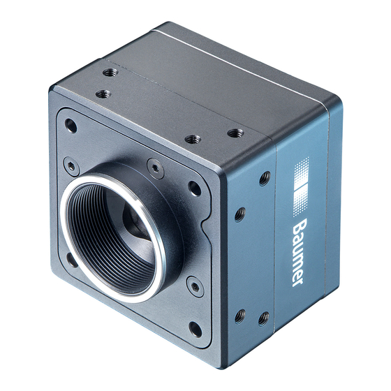
Full Sensor Camera Type Resolution Frames Size [max. fps] HXC20 2/3" 2048x1088 HXC40 1" 2048x2048 HXC20c 2/3" 2048x1088 HXC40c 1" 2048x2048 Dimensions UNC 1/4 20 16 x M3 depth 6 37,4 Figure 2 ► Dimensions of a Baumer HXC camera with C-Mount. -
Page 7: Hxc-F - Cameras With F-Mount
HXC-F – Cameras with F-Mount ◄ Figure 3 Front view of a Baumer HXC camera with F- Mount Full Sensor Camera Type Resolution Frames Size [max. fps] HXC20-F 2/3" 2048x1088 HXC40-F 1" 2048x2048 HXC20c-F 2/3" 2048x1088 HXC40c-F 1" 2048x2048 Dimensions UNC 1/4 20 16 x M3 depth 6 ◄ Figure 4... -
Page 8: Product Specifications
BGAPI 1.x - CL Config Tool: CameraInformation: Hardware Version (CID Firmware 1.0 starts with 02 / CID Firmware 2.0 starts with 03 (e.g. CID:030004 - Firmware 2.0) • Read out register 0x00000088 (see HXC Register Description Release 2) 6.2 Sensor Specifications 6.2.1 Identification of Sensor Version • Read out register 0xF0004600 (see HXC Register Description Release 2) 6.2.2 Quantum Efficiency for Baumer HXC Cameras The quantum efficiency characteristics of monochrome (also in NIR) and color matrix sen- sors for Baumer HXC cameras are displayed in the following graphs. The characteristic curves for the sensors do not take the characteristics of lenses and light sources without filters into consideration, but are measured with an AR coated cover glass. Values relating to the respective technical data sheets of the sensors manufacturer. Figure 5 ► 1050 1050 Quantum efficiency for HXC 20/40 (monochrome) HXC 20/40 (color) Wave Length [nm] Wave Length [nm] Baumer HXC cameras. -
Page 9: Digitization Taps
Global shutter means that all pixels of the sensor are reset and afterwards exposed for a specified interval (t ). exposure For each pixel an adjacent storage circuit exists. Once the exposure time elapsed, the information of a pixel is transferred immediately to its circuit and read out from there. Due to the fact that photosensitive area gets "lost" by the implementation of the circuit area, the pixels are equipped with microlenses, which focus the light on the pixel. 6.2.4 Digitization Taps The Truesense sensors, employed in Baumer HXC cameras can be read out up to 16 channels in parallel. Notice More channels increase the speed (framerate), but the use of more channels produces a higher heat generation. Use only the maximum required number of channels! Notice Due to sensor characteristics in 12 bit mode only 2 or 4 channels are available. Readout with 16 Channels Readout with 8 Channels ◄ Figure 7 Digitization Tap of the Baumer HXC Cameras Readout with 4 Channels Readout with 2 Channels... -
Page 10: Timings
Timings Notice Overlapped mode can be switched off with setting the readout mode to sequential shut- ter instead of overlapped shutter. The image acquisition consists of two separate, successively processed components. Exposing the pixels on the photosensitive surface of the sensor is only the first part of the image acquisition. After completion of the first step, the pixels are read out. The exposure time (t ) can be adjusted by the user, however, the time needed for the exposure readout (t ) is given by the particular sensor, image format and configuration. readout Baumer HXC cameras can be operated with two modes, the Free Running Mode and the Trigger Mode. The cameras can be operated non-overlapped or overlapped. Depending on the mode used, and the combination of exposure and readout time: Non-overlapped Operation Overlapped Operation Here the time intervals are long enough In this operation the exposure of a frame to process exposure and readout succes- (n+1) takes place during the readout of sively. frame (n). Exposure Exposure Readout Readout 6.3.1 Free Running Mode In the "Free Running" mode the camera records images permanently and sends them to ... -
Page 11: Trigger Mode
6.3.2 Trigger Mode After a specified external event (trigger) has occurred, image acquisition is started. De- pending on the interval of triggers used, the camera may operate non-overlapped or over- lapped in this mode, when overlapped mode is enabled. With regard to timings in the trigger mode, the following basic formulas need to be taken into consideration: Case Formula earliestpossibletrigger(n+1) readout(n) exposure(n+1) < t exposure readout + t notready(n+1) exposure(n) readout(n) exposure(n+1) earliestpossibletrigger(n+1) exposure(n) > t exposure readout notready(n+1) exposure(n) 6.3.2.1 Overlapped Operation: t exposure(n+2) exposure(n+1) In overlapped operation attention should be paid to the time interval where the camera is unable to process occuring trigger signals (t ). This interval is situated between two notready exposures. When this process time t ... - Page 12 6.3.2.2 Overlapped Operation: t > t exposure(n+2) exposure(n+1) If the exposure time (t ) is increased from the current acquisition to the next acquisi- exposure tion, the time the camera is unable to process occuring trigger signals (t ) is scaled notready down. This can be simulated with the formulas mentioned above (no. 2 or 4, as is the case). Trigger triggerdelay exposure(n) exposure(n+1) exposure(n+2) Exposure Timings: A - exposure time frame (n) effective B - image parameters frame (n) effective readout(n) readout(n+1) Readout C - exposure time frame (n+1) effective D - image parameters frame (n+1) effective...
- Page 13 6.3.2.3 Overlapped Operation: t < t exposure(n+2) exposure(n+1) If the exposure time (t ) is decreased from the current acquisition to the next acquisi- exposure tion, the time the camera is unable to process occuring trigger signals (t ) is scaled notready When decreasing the t such, that t exceeds the pause between two incoming exposure notready trigger signals, the camera is unable to process this trigger and the acquisition of the im- age will not start (the trigger will be skipped). Trigger triggerdelay exposure(n) exposure(n+1) exposure(n+2 Timings: Exposure A - exposure time frame (n) effective B - image parameters frame (n) effective readout(n) readout(n+1) C - exposure time...
- Page 14 6.3.2.4 Non-overlapped Operation If the period between two trigger pulses is long enough, so that the image acquisitions + t ) run successively, the camera operates non-overlapped. In the following exposure readout figure is the shutter mode set to non-overlapped. Trigger triggerdelay exposure(n) exposure(n+1) Exposure Timings: A - exposure time frame (n) effective B - image parameters frame (n) effective readout(n) readout(n+1) Readout C - exposure time frame (n+1) effective D - image parameters frame (n+1) effective E - earliest possible trigger notready...
-
Page 15: Field Of View Position
6.4 Field of View Position The typical accuracy by assumption of the root mean square value is displayed in the figures and the table below: ±X ±X Photosensitive surface of the sensor ◄ Figure 8 Sensor accuracy of ±Z Baumer HXC cameras. Camera ± x ± y ± x ± y ± β ± z M,typ M,typ R,typ... -
Page 16: Process- And Data Interface
Process- and Data Interface 6.5.1 Pin-Assignment Camera Link Interface ® Notice The camera has two Camera Link sockets. To differentiate between Cam- CL FULL Baumer era Link Base and CamerLink Full socket, please look at the label. Type HXCXXx (xxxxxxx) 000XXXXX R1 0 You can not use the CL Full socket alone! CL BASE L BA Caution When fixing the Camera Link cable with too much force the screws might ® get damaged. The maximum torque is 2.5 inch lbf [0.3 Nm]. Date / Camera Link Full ®... -
Page 17: Pin-Assignment Power Supply And Digital Ios
6.5.2 Pin-Assignment Power Supply and Digital IOs Caution A power supply with electrical isolation is required for proper operation of the camera. Otherwise the device may be damaged. M8 / 3 pins M8 / 8 pins (brown) Power V (white) Line 9 (blue) (brown) Line 1 (black) not used (green) Line 0 (yellow) (grey) (pink) Line 7 (blue) Line 8 (red) Line 2 Power Supply Power VCC 9,6 VDC ... 30 VDC Mono8, Camera Link base, dual tap, 40 MHz; 190 mA .. 550 Mono8, Camera Link full, 10 tap, 48 MHz; 200 mA .. 620 mA Power consumption approx. 5.5 Watt (with camera factory settings) 6.5.3 LED Signaling Signal... -
Page 18: Environmental Requirements
**)***) HXC20 max. +65 °C (+149 °F) HXC40 max. +65 °C (+149 °F) Internal operating temperature HXC20 max. +60 °C (+140 °F) HXC40 max. +60 °C (+140 °F) Humidity Storage and Operating Humidity 10% ... 90% Non-condensing Figure 9 ► Temperature measure- ment points of Baumer HXC cameras. 6.6.2 Heat Transmission Caution Provide adequate dissipation of heat, to ensure that the temperature does not exceed the spedified temperature (+65°C /+149°F). The surface of the camera may be hot during operation and immediately after use. Be careful when handling the camera and avoid contact over a longer period. It is very important to provide adequate dissipation of heat, to ensure that the housing temperature does not reach or exceed +65°C (+149°F). As there are numerous possibili- ties for installation, Baumer do not specifiy a specific method for proper heat dissipation, but suggest the following principles: ▪ operate the cameras only in mounted condition ▪... -
Page 19: Mechanical Tests
6.6.3 Mechanical Tests Environmental Standard Parameter Testing Vibration, sinu- IEC 60068-2-6 Search for Reso- 10-2000 Hz sodial nance Amplitude under- 1.5 mm neath crossover frequencies Acceleration Test duration 15 min Vibration, IEC 60068- Frequency range 20-1000 Hz broad band 2-64 Acceleration 10 g Displacement 5.7 mm Test duration 300 min Shock IEC 60068-... -
Page 20: Software
, as well as Mono on Linux operating systems, which offers the ® ® use of other languages, such as e.g. C# or VB.NET. The HXC camera features are in general supported by Baumer GAPI v 1.7.2. However, to use the new release 2 features (e.g. HDR and Multi-ROI) Baumer GAPI v 2.1 is re- quired. Notice There is currently no Baumer GAPI version for Linux available with support for Camera Link ® Notice Please note the extra instructions to the software Baumer GAPI. Specifically for Camera Link Cameras, the "User´s Guide CLConfig Tool". ®... -
Page 21: Image Format
Camera Functionalities 8.1 Image Acquisition 8.1.1 Image Format A digital camera usually delivers image data in at least one format - the native resolution of the sensor. Baumer cameras are able to provide several image formats (depending on the type of camera). Compared with standard cameras, the image format on Baumer cameras not only in- cludes resolution, but a set of predefined parameter. These parameters are: ▪ Resolution (horizontal and vertical dimensions in pixels) ▪ Binning Mode (combining of neighboring pixels) ▪ Subsampling (not every pixel is read) Camera Type HXC20 ■ ■ ■ HXC40 ■... -
Page 22: Pixel Format
8.1.2 Pixel Format On Baumer digital cameras the pixel format depends on the selected image format. 8.1.2.1 Pixel Formats on Baumer HXC Cameras Camera Type Mono HXC20 ■ ■ ■ □ □ □ HXC40 ■ ■ ■ □ □ □ Color HXC20c □ □ □ ■ ■ ■ HXC40c □ □ □ ■ ■ ■ 8.1.2.2 Definitions Below is a general description of pixel formats. The table above shows, which camera ... - Page 23 RGB: Color model, in which all detectable colors are defined by three coordinates, Red, Green and Blue. ◄ Figure 11 RBG color space dis- played as color tube. The three coordinates are displayed within the buffer in the order R, G, B. BGR: Here the color alignment mirrors RGB. YUV: Color model, which is used in the PAL TV standard and in image compression. In YUV, a high bandwidth luminance signal (Y: luma information) is transmitted together with two color difference signals with low bandwidth (U and V: chroma information). Thereby U represents the difference between blue and luminance (U = B - Y), V is the difference between red and luminance (V = R - Y). The third color, green, does not need to be transmitted, its value can be calculated from the other three values. YUV 4:4:4 Here each of the three components has the same sample rate. Therefore there is no subsampling here. YUV 4:2:2 The chroma components are sampled at half the sample rate. This reduces the necessary bandwidth to two-thirds (in relation to ...
-
Page 24: Exposure Time
8.1.3 Exposure Time On exposure of the sensor, the inclination of photons produces a charge separation on the semiconductors of the pixels. This results in a voltage difference, which is used for signal extraction. Figure 15 ► Incidence of light causes charge separation on the semiconductors of the sensor. The signal strength is influenced by the incoming amount of photons. It can be increased by increasing the exposure time (t exposure On Baumer HXC cameras, the exposure time can be set within the following ranges (step size 1μsec): Camera Type exposure exposure HXC20 / HXC20c 4 μsec 1 sec HXC40 / HXC40c 4 μsec 1 sec 8.1.4 PRNU / DSNU Correction (FPN - Fixed Pattern Noise) CMOS ... -
Page 25: High Dynamic Range (Hdr)
8.1.5 High Dynamic Range (HDR) Beside the standard linear response the sensor supports a special high dynamic range mode (HDR) called piecewise linear response. With this mode illuminated pixels that reach a certain programmable voltage level will be clipped. Darker pixels that do not reach this threshold remain unchanged. The clipping can be adjusted two times within a single exposure by configuring the respective time slices and clipping voltage levels. See the figure below for details. In this mode, the values for t , t , Pot and Pot can be edited. Expo0 Expo1 The value for t will be calculated automatically in the camera. (t Expo2 Expo2 exposure Expo0 Expo1 HDR Off HDR On Pot 2 Pot 1 Illumination Pot 0... -
Page 26: Gamma Correction
8.1.7 Gamma Correction With this feature, Baumer HXC cameras offer the possibility of compensating nonlinearity in the perception of light by the human eye. For this correction, the corrected pixel intensity (Y') is calculated from the original intensity of the sensor's pixel (Y ) and correction factor γ using the following formula (in over- original simplified version): ▲ Figure 16 Non-linear perception of γ the human eye. Y' = Y original H - Perception of bright- ness E - Energy of light 8.1.8 Region of Interest (ROI) and Multi-ROI With this functions it is possible to predefine a so-called Region of Interest (ROI) or Partial Scan. The ROI is an area of pixels of the sensor. After image acquisition, only the informa- tion of these pixels is sent to the PC. This functions is turned on, when only a region of the field of view is of interest. It is ... - Page 27 8.1.8.1 Normal- ROI Readout (Region 0) For the sensor readout time of the ROI, the horizontal subdivision of the sensor is unim- portant – only the vertical subdivision is of importance. The activation of ROI turns off all Multi-ROIs. Start ROI End ROI ◄ Figure 18 ROI: Readout The readout of the sensor is line based, which means always a complete line of pixels needs to be read out and afterwards the irrelevant information is discarded. End ROI Start ROI ◄ Figure 19 ROI: Discarded Information 8.1.8.2 Multi-ROI With Multi-ROI it is possible to predefine several Region of Interests (ROIs). It can be specified up to 8 horizontal and vertical stripes (total up to 64 ROIs). Overlapped Multi- ROIs will be merged by the camera. The Multi-ROI´s are sorted by the camera. ...
-
Page 28: Binning / Subsampling
8.1.9 Binning / Subsampling Notice Binning and Subsampling are only available at monochrome cameras. Baumer HXC cameras support horizontal Binning. In binning, horizontally neighboring pixels are aggregated and reported to the software as one single "superpixel". When subsampling, only certain pixels are read out. (Subsampling 2x2 = every second pixel in every second line.) Binning Illustration Example without Figure 21 ► Full frame image, no binning of pixels. Figure 22 ► Horizontal binning causes a horizontally compressed image with doubled brightness. Subsam- pling 2x2 Figure 23 ► Subsampling 2x2 causes both a hori- zontally and vertically compressed image... -
Page 29: Brightness Correction (Binning Correction)
8.1.10 Brightness Correction (Binning Correction) The summation of pixel values may cause an overload. To prevent this, binning correction was introduced. Binninig Realization 2x1 binning takes place within the FPGA of the camera. The binning cor- rection is realized by averaging the pixel values instead of simply adding them. 8.2 Color Adjustment – White Balance This feature is available on all color cameras of the Baumer HXC series. White balance means independent adjustment of the three color channels, red, green and blue by employing of a correction factor for each channel. 8.2.1 User-specific Color Adjustment The user-specific color adjustment in Baumer color cameras facilitates adjustment of the correction factors for each color gain. This way, the user is able to adjust the amplifica- tion of each color channel exactly to his needs. The correction factors for the color gains range from 1.0 to 4.0. non-adjusted histogramm after histogramm user-specific color adjustment ◄ Figure 24 Examples of histo- gramms for a non- adjusted ... -
Page 30: Analog Controls
Analog Controls 8.3.1 Offset / Black Level On Baumer cameras, the offset (or black level) is adjustable from 0 to 255 LSB (always related to 12 bit). 8.3.2 Gain digital In industrial environments motion blur is unacceptable. Due to this fact exposure times are limited. However, this causes low output signals from the camera and results in dark images. To solve this issue, the signals can be amplified by a user-defined gain factor within the camera. This gain factor is adjustable from 1.0 to 4.0. Notice Increasing the gain factor causes an increase of image noise and leads to missing codes at Mono12, if the gain factor > 1.0... -
Page 31: Defect Pixel Correction
Charge quantity „Cold Pixel“ ◄ Figure 27 Charge quantity of "hot" and "cold" pixels com- pared with "normal" pixels. 8.4.2 Correction Algorithm On monochrome cameras of the Baumer SXC series, the problem of defect pixels is solved as follows: ▪ Possible defect pixels are identified during the production process of the camera. ▪ The coordinates of these pixels are stored in the factory settings of the camera. ▪ Once the sensor readout is completed, correction takes place: ▪... -
Page 32: Sequencer
Sequencer 8.5.1 General Information A sequencer is used for the automated control of series of images using different sets of parameters. Figure 29 ► Flow chart of sequencer. m - number of sequence repeti- tions n - number of set repetitions o - number of sets of parameters z - number of frames per trigger The figure above displays the fundamental structure of the sequencer module. The loop counter (m) represents the number of sequence repetitions. Sequencer Parameter: The repeat counter (n) is used to control the amount of images taken with the respective The mentioned sets of sets of parameters. For each set there is a separate n. ... -
Page 33: Examples
Sequencer ▪ Different objects can be Start captured without hardware changes ◄ Figure 32 Example for a half-auto- Trigger mated sequencer. The figure above shows an example for a half-automated sequencer with three sets of parameters (A,B and C) from the previous example. The frame counter (z) is set to 2. This means the camera records two pictures after an incoming trigger signal. 8.5.3 Capability Characteristics of Baumer-GAPI Sequencer Module ▪ up to 128 sets of parameters ▪ up to 4 billion loop passes ▪ up to 4 billion repetitions of sets of parameters ▪ up to 4 billion images per trigger event ▪ free running mode without initial trigger... -
Page 34: Shutter
8.5.4 Double Shutter This feature offers the possibility of capturing two images in a very short interval. Depend- ing on the application, this is performed in conjunction with a flash unit. Thereby the first exposure time (t ) is arbitrary and accompanied by the first flash. The second expo- exposure sure time must be equal to, or longer than the readout time (t ) of the sensor. Thus the readout pixels of the sensor are recepitve again shortly after the first exposure. In order to realize the second short exposure time without an overrun of the sensor, a second short flash must be employed, and any subsequent extraneous light prevented. Trigger Flash Exposure Prevent Light Figure 33 ► Example of a double Readout shutter. On Baumer TXG cameras this feature is realized within the sequencer. In order to generate this sequence, the sequencer must be configured as follows: Parameter Setting: Sequencer Run Mode Once by Trigger Sets of parameters (o) Loops (m) Repeats (n) Frames Per Trigger (z) -
Page 35: Process Interface
Process Interface 8.6.1 Digital IOs Cameras of the Baumer HXC series are equipped with three input lines and three output lines. 8.6.1.1 Circuits Notice Low Active: At this wiring, only one consumer can be connected. When all Output pins (1, 2, 3) connected to IO_GND, then current flows through the resistor as soon as one Output is switched. If only one output connected to IO_GND, then this one is only us- able. The other two Outputs are not usable and may not be connected (e.g. IO Power V Output high active Output low active Input Camera Customer Device Camera Customer Device Customer Device Camera IO Power V CC IN1 Pin IO Power V CC I OUT Pin (Out1, 2, 3) - Page 36 8.6.1.3 Configurable Outputs With this feature, Baumer offers the possibility of wiring the output connectors to internal signals, which are controlled on the software side. Hereby on cameras of the HXC series, 21 signal sources – subdivided into three catego- ries – can be applied to the output connectors. The first category of output signals represents a loop through of signals on the input side, such as: Signal Name Explanation Line0 Signal of input "Line0" is loopthroughed to this ouput Line1 Signal of input "Line1" is loopthroughed to this ouput Line2 Signal of input "Line2" iys loopthroughed to this ouput FrameGrabberLine0 Signal of input "FrameGrabberLine0" is loopthroughed to this ouput FrameGrabberLine1 Signal of input "FrameGrabberLine1" is loopthroughed to this ouput FrameGrabberLine2 Signal of input "FrameGrabberLine2" is loopthroughed to this ouput FrameGrabberLine3 Signal of input "FrameGrabberLine3" is loopthroughed to this ouput Within the second category you will find signals that are created on camera side: Signal Name Explanation FrameActive The camera processes a Frame consisting of exposure ...
-
Page 37: Trigger Input / Trigger Delay
FrameGrabberLine2 Line2 FrameGrabberLine3 FrameGrabberLine0 SW-Trigger Figure 36 ▲ Trigger signal, valid for There are three types of modes. The timing diagrams for the three types you can see Baumer cameras. below. Normal Trigger with adjusted Exposure Camera in trigger mode: A - Trigger delay Trigger (valid) B - Exposure time... -
Page 38: Trigger Source
8.6.3 Trigger Source Figure 37 ► Examples of possible trigger sources. Each trigger source has to be activated seperately. When the trigger mode is activated, the hardware trigger is activated by default. -
Page 39: Debouncer
◄ Figure 38 DebounceHigh user defined debouncer delay for state low Principle of the Baumer DebounceLow debouncer. 8.6.5 Flash Signal On Baumer cameras, this feature is realized by the internal signal "ExposureActive", which can be wired to one of the digital outputs. -
Page 40: Timer
Frame Start TriggerSkipped Frame End SW-Trigger For example the using of a timer allows you to control the flash signal in that way, that the illumination does not start synchronized to the sensor exposure but a predefined interval earlier. For this example you must set the following conditions: Setting Value TriggerSource InputLine0 TimerTriggerSource InputLine0 Outputline7 (Source) Timer1Active TimerTriggerActivation Falling Edge Trigger Polarity Falling Edge InputLine0 triggerdelay exposure Exposure TimerDelay Figure 39 ► TimerDuration Possible Timer con- Timer figuration on a Baumer HXC canera. -
Page 41: User Sets
User Sets Three user sets (1-3) are available for the Baumer cameras of the HXC series. The user sets can contain the following information: Parameter Parameter Binning Mode Mirroring Control Camera Link Control Offset ® Defectpixellist Partial Scan Digital I/O Settings Pixelformat Exposure Time Readout Mode/Digitization Taps Gain Factor Testpattern Look-Up-Table Trigger Settings Shutter Mode Fixed Frame rate Color Gains Gamma Speed Mode IO-Settings These user sets are stored within the camera and and cannot be saved outside the de- vice. By employing a so-called "user set default selector", one of the three possible user sets can be selected as default, which means, the camera starts up with these adjusted pa- rameters. Factory Settings The factory settings are stored in an additional parametrization set which is used by de-... -
Page 42: Camera Link ® Interface
Camera Link Interface ® The Camera Link interface was specifically developed for cameras in machine vision ap- ® plications and provides high transfer rates and low latency. Depending on the configura- tion (Base, Medium or Full) the transfer rate adds up to 800 MBytes/sec. Cameras of the Baumer HXC series are equipped with a Camera Link Full interface and ® therewith able to transmit up to 800 MBytes/sec. 9.1 Channel Link and LVDS Technology Camera Link bases upon the Channel Link technology, but provides a specification, that ® ® is more beneficial for machine vision. Channel Link in turn is an advancement of the LDVS (Low Voltage Differential Signaling) ® standard – a low power, high speed interface standard. The Channel Link technology consists of a transmitter receiver pair with 21, 28 or 48 ... -
Page 43: Camera Control
▪ no handshaking. 9.2.2 Camera Control According to the Camera Link standard four LVDS pairs have to be reserved for general- ® purpose camera control. They are defined as frame grabber outputs and camera inputs. The definition of these signals is left to the camera manufacturer. Signal Baumer Naming Employment Camera Control 1 (CC1) FrameGrabberLine0 Camera Control 2 (CC2) FrameGrabberLine1 On Baumer HXC cameras, the wiring of these signals is arbitrary. Camera Control 3 (CC3) FrameGrabberLine2 Camera Control 4 (CC4) FrameGrabberLine3 9.2.3 Video Data The standard designates four signals (as well as the signal state) for the validation of ... -
Page 44: Cameralink ® Taps
9.3 Camera Link Taps ® The standard defines a tap as "the data path carrying a stream of pixels". This means the number of taps equates to the number of simultaneously transferred pixel. Notice Please do not mix up sensor digitization taps and Camera Link taps! ® 9.3.1 Tap Configuration Within the subsequent sections, the transmission of images with different pixel formats (bit depth) linked to the employment of different numbers of taps is displayed. Configuration Cables CL Base (1T8, 2T8, 3T8, 1T10, 2T10, 1T12, 2T12) CL Medium (3T10, 3T12, 4T8, 4T10 4T12) CL Full (8T8) CL Deca (10T8) 9.3.1.1 CL Base 8-bit Monochrome Single Tap Transmission (1T8) Tap 1 Tap 1 Tap 1 Tap 1 Tap 1 Tap 1 Tap 1 Tap 1 Port A bit 0... - Page 45 9.3.1.4 CL Base 10-bit Monochrome Single Tap Transmission (1T10) Tap 1 Tap 1 Tap 1 Tap 1 Tap 1 Tap 1 Tap 1 Tap 1 Port A bit 0 bit 1 bit 2 bit 3 bit 4 bit 5 bit 6 bit 7 Tap 1 Tap 1 Port B bit 8 bit 9 Port C 9.3.1.5 CL Base 10-bit Monochrome Dual Tap Transmission (2T10) Tap 1...
- Page 46 9.3.1.9 CL Medium 12-bit Monochrome Triple Tap Transmission (3T12) Tap 1 Tap 1 Tap 1 Tap 1 Tap 1 Tap 1 Tap 1 Tap 1 Port A bit 0 bit 1 bit 2 bit 3 bit 4 bit 5 bit 6 bit 7 Tap 1 Tap 1 Tap 1 Tap 1 Tap 2 Tap 2...
- Page 47 9.3.1.13 CL Full 8-bit Monochrome Eight Tap Transmission (8T8) Tap 1 Tap 1 Tap 1 Tap 1 Tap 1 Tap 1 Tap 1 Tap 1 Port A bit 0 bit 1 bit 2 bit 3 bit 4 bit 5 bit 6 bit 7 Tap 2 Tap 2 Tap 2 Tap 2 Tap 2 Tap 2...
-
Page 48: Tap Geometry
9.3.2 Tap Geometry Since frame grabbers possess the ability of image reconstruction from multi-tap cameras "on-the-fly", the Camera Link standards demands the specification of the used / sup- ® ported tap geometries from the manufacturers of both, cameras and frame grabbers. 9.3.2.1 Single Tap Geometry For single tap transmission the cameras of the Baumer HXC series employ the 1X-1Y tap geometry: Figure 41 ► Tap geometry 1X-1Y. The pixel information is transmitted pixel-by- pixel and line-by-line. 9.3.2.2 Dual Tap Geometry For dual tap transmission the cameras of the Baumer HXC series employ the 1X2-1Y tap ... - Page 49 9.3.2.4 Quad, Eight and Ten Tap Geometry For Quad, Eight and Ten tap transmission the cameras of the Baumer HXC series use the same system. ◄ Figure 44 Tap geometry 1X4...10-...
-
Page 50: Lens Install
Lens install Notice Avoid contamination of the sensor and the lens by dust and airborne particles when mounting a lens to the device! Therefore the following points are very important: ▪ Install lenses in an environment that is as dust free as possible! ▪ Keep the dust covers on camera and lens as long as possible! ▪ Hold the camera downwards with unprotected sensor (or filter- /cover glass)! ▪ Avoid contact with any optical surface of the camera or lens! At the example on the figures below the installation of C-mount objective is shown. At a camera with F-Mount it is principle the same. 1. Turn the camera with the lens mount to the bottom. 2. Unscrew the protective cap. 3. Screw the lens on the lens mount. -
Page 51: Cleaning
Cleaning Cover glass Notice The sensor is mounted dust-proof. Remove of the cover glass for cleaning is not neces- sary. Avoid cleaning the cover glass of the CCD sensor if possible. To prevent dust, follow the instructions under "Install lens". If you must clean it, use compressed air or a soft, lint free cloth dampened with a small quantity of pure alcohol. Housing Caution! Volatile solvents for cleaning. Volatile solvents damage the surface of the camera. volatile solvents Never use volatile solvents (benzine, thinner) for cleaning! To clean the surface of the camera housing, use a soft, dry cloth. To remove persistent stains, use a soft cloth dampened with a small quantity of neutral detergent, then wipe dry. Transport / Storage Notice Transport the camera only in the original packaging. When the camera is not installed, then storage the camera in original packaging. Storage Environment Storage temperature -10°C ... +70°C ( +14°F ... +158°F) Storage Humidy 10% ... 90% non condensing... -
Page 52: Disposal
Disposal Dispose of outdated products with electrical or electronic circuits, not in the normal domestic waste, but rather according to your national law and the directives 2002/96/EC and 2006/66/EC for recycling within the competent collectors. Through the proper disposal of obsolete equipment will help to save valu- able resources and prevent possible adverse effects on human health and the environment. The return of the packaging to the material cycle helps conserve raw mate- rials an reduces the production of waste. When no longer required, dispose of the packaging materials in accordance with the local regulations in force. Keep the original packaging during the warranty period in order to be able to pack the device properly in the event of a warranty claim. Warranty Information Notice There are no adjustable parts inside the camera! In order to avoid the loss of warranty do not open the housing! Notice If it is obvious that the device is / was dismantled, reworked or repaired by other than Baumer technicians, Baumer Optronic will not take any responsibility for the subse- quent performance and quality of the device! -
Page 53: Conformity
Conformity Cameras of the Baumer HXC family comply with: ▪ ▪ FCC Part 15 Class B, ▪ RoHS 15.1 We declare, under our sole responsibility, that the previously described Baumer HXC cameras conform with the directives of the CE. 15.2 FCC – Class B Device : This equipment has been tested and found to comply with the limits for a Class B digital device, pursuant to part 15 of the FCC Rules. These limits are designed to provide reasonable protection against harmful interference in a residential environment. This equipment generates, uses, and can radiate radio frequency energy and, if not in- stalled and used in accordance with the instructios, may cause harmful interference to radio communications. However, there is no guarantee that interference will not occure in a particular installation. If this equipment does cause harmful interference to radio or television reception, which can be determined by turning the equipment off an on, the user is encouraged to try to correct the interference by one or more of the following measures: ▪ Reorient or relocate the receiving antenna. ▪ Increase the separation between the equipment and the receiver. ▪ Connect the equipment into an outlet on a circuit different from that to which the receiver is connected.
Need help?
Do you have a question about the Camera Link HXC Series and is the answer not in the manual?
Questions and answers