Advertisement
Quick Links
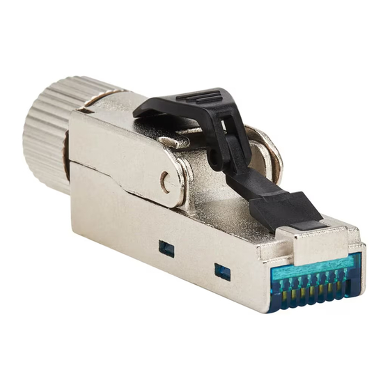
Installation Instructions
Cat6a Class EA STP
Field Termination Plug,
568A/568B
Model: N232-SHC6A-1
Este manual está disponible en español en la página
de Tripp Lite: tripplite.com
Ce manuel est disponible en français sur le site Web
de Tripp Lite : tripplite.com
Русскоязычная версия настоящего руководства
представлена на веб-сайте компании Tripp Lite по
Dieses Handbuch ist in deutscher Sprache auf der
Tripp Lite-Website verfügbar: tripplite.com
WARRANTY REGISTRATION
Register your product today and be automatically entered
to win an ISOBAR
tripplite.com/warranty
1111 W. 35th Street, Chicago, IL 60609 USA
tripplite.com/support
Copyright © 2023 Tripp Lite. All rights reserved.
адресу: tripplite.com
surge protector in our monthly drawing!
®
1
Advertisement

Related Manuals for Tripp Lite N232-SHC6A-1


Summary of Contents for Tripp Lite N232-SHC6A-1
- Page 1 Tripp Lite-Website verfügbar: tripplite.com WARRANTY REGISTRATION Register your product today and be automatically entered to win an ISOBAR surge protector in our monthly drawing! ® tripplite.com/warranty 1111 W. 35th Street, Chicago, IL 60609 USA tripplite.com/support Copyright © 2023 Tripp Lite. All rights reserved.
-
Page 2: Installation
Installation TIA / EIA TIA / EIA INDUS- T568A T568B TRIAL White/Green White/Orange Yellow Green Orange Orange White/Orange White/Green White Orange Green Blue Blue White/Blue White/Brown Brown... - Page 3 Installation Cable Preparation 2 in. (50 mm) 0.2 in. (5 mm) OD Φ0.2~0.24 in. 1.2 in. (30 mm) (5~6 mm) 0.3 in. (8 mm) OD Φ0.2~0.3 in. (6.1~7.9 mm) OD Φ0.3~0.4 in. 0.3 in. (8~9 mm) (8 mm) (No folded braiding) 1.2 in.
- Page 4 Installation Step 1: Insert cable through cable gland, follow the Cable Preparation diagrams according to cable used. Fan out all four twisted pairs and cut the conductors as shown. Notes: Cable • The cable bushing is inserted inside the cable gland during Bushing production.
- Page 5 Installation Step 2: Follow the color-coding label and insert each conductor into the proper slots on the wiring cap. Trim the ends of the excess conductors. Step 3: Remove the wiring label before placing the wiring cap on the plug. Wiring Label...
- Page 6 Installation Step 4: Place the wiring cap on the plug. Clamp down the wiring cap with pliers until it completely snaps in to establish the connection. Ensure the drain wire or braiding are in contact with the grounding clip. Grounding clip Drain wire and braid Drain wire and braid cannot exceed...
- Page 7 Installation Step 5: Close the plug cover. Make sure the drain wire is in proper contact with the grounding clip on the plug. Screw on the cable gland to fasten and complete the installation.
-
Page 8: Uninstalling The Cable
Uninstalling the Cable Step 1: Release Cable Gland Step 2: Open Plug Cover Step 3: Release Wiring Cap... -
Page 9: Warranty And Product Registration
Service under this Warranty can only be obtained by your delivering or shipping the product (with all shipping or delivery charges prepaid) to: TRIPP LITE; 1111 W. 35th Street, Chicago, IL 60609. Seller will pay return shipping charges. Visit tripplite.com/support before sending any equipment back for repair. - Page 10 Visit tripplite.com/warranty today to register your new Tripp Lite product. You’ll be automatically entered into a drawing for a chance to win a FREE Tripp Lite product!* * No purchase necessary. Void where prohibited. Some restrictions apply. See website for details.
- Page 12 1111 W. 35th Street, Chicago, IL 60609 USA tripplite.com/support 22-11-155 93-46DC RevA...
Need help?
Do you have a question about the N232-SHC6A-1 and is the answer not in the manual?
Questions and answers