Advertisement
Quick Links
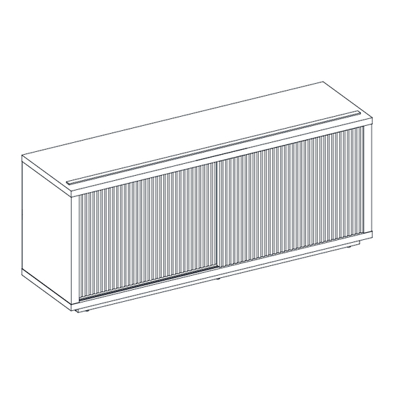
Stock # WL-BT-014 (Light Honey)
If you have any questions regarding assembly or if parts are missing, DO NOT return this item to the
store where it was purchased. Please call our customer service number and have your instructions
and parts list ready to provide the model name, part name or factory number:
Pacific Standard Time: 8:30 a.m. - 4:30 p.m., Monday - Friday
Or visit our web site 24 hours a day, 7 days a week for product assistance at
THIS INSTRUCTION BOOKLET CONTAINS IMPORTANT SAFETY INFORMATION.
Fluted TV Stand
# WL-BT-015 (Black)
ADULT ASSEMBLY REQUIRED
1-866-942-5362
www.whalenstyle.com
Or e-mail your request to parts@whalenfurniture.com
PLEASE READ AND KEEP FOR FUTURE REFERENCE.
Date 2023-12-29
LOT NUMBER:
DATE PURCHASED:
Rev. 0001-C
/
/
Advertisement

Subscribe to Our Youtube Channel
Related Manuals for Beautiful WL-BT-014


Summary of Contents for Beautiful WL-BT-014
- Page 1 LOT NUMBER: DATE PURCHASED: Fluted TV Stand Stock # WL-BT-014 (Light Honey) # WL-BT-015 (Black) ADULT ASSEMBLY REQUIRED If you have any questions regarding assembly or if parts are missing, DO NOT return this item to the store where it was purchased. Please call our customer service number and have your instructions...
-
Page 2: Special Note
IMPORTANT Before you begin: Open, identify and count all parts prior to assembly. Lay out parts on a flat and non-abrasive surface. You will need the parts identified on page 3 and 4 of this instruction manuals. NOTE: IT IS VERY IMPORTANT TO USE GLUE WITH DOWELS. EXCESS GLUE CAN BE WIPED OFF WITH DAMP CLOTH. - Page 3 Parts and Hardware List Please read completely through the instructions and verify that all listed parts and hardware are present before beginning assembly. A- Top Panel B- Bottom Panel C- Left Side Panel (Qty. 1) (Qty. 1) (Qty. 1) D- Right Side Panel E- Partition Panel F- Front Skirting (Qty.
- Page 4 Parts and Hardware List Please read completely through the instructions and verify that all listed parts and hardware are present before beginning assembly. (1) Cam Lock (2) Cam Bolt (3) M8 x 30 mm Wood Dowel (Qty. 14+1 extra) (Qty. 14+1 extra) (Qty.
- Page 5 Assembly Instructions ② x 8 NOTE: Please do not fully tighten all screws and bolts until you finish assembling all parts. Once assembled, go back and fully tighten all screws and bolts. This will make the assembly easier. 1. Unpack the unit and confirm that you have all the hardware and required parts. Assemble the unit on a carpeted floor or the empty carton to avoid any scratch.
- Page 6 Assembly Instructions ② x 6 3. Securely screw six Cam Bolts (2) into the designated small holes on the Skirtings (F, G, H and J) with a Phillips screwdriver.
- Page 7 Assembly Instructions ③ x 10 4. Glue ten Wood Dowels (3) into the designated holes on the Skirtings (F, G, H and J) and Bottom Middle Stretcher (I). Make sure that you use a small amount of glue with both ends of all dowels. NOTE: It is very important to use a small amount of glue on both ends of dowels and wipe away the excess glue immediately with a damp cloth.
- Page 8 Assembly Instructions ③ x 12 5. Glue twelve Wood Dowels (3) into the designated holes on the Panels (C, D and E).
- Page 9 Assembly Instructions The wood dowels face in the same direction. ① x 2 6. Orient and attach the Rear Skirting (J) between the Left Skirting (G) and Right Skirting (H) by engaging two Cam Locks (1). (Refer to page 2 on Cam Lock system operation supplement).
- Page 10 Assembly Instructions The wood dowels face in the same direction. ① x 1 7. Orient and attach the Bottom Middle Stretcher (I) to the Rear Skirting (J) by engaging one Cam Lock (1).
- Page 11 Assembly Instructions The wood dowels face in the same direction. ① x 3 8. Repeat the same procedure to attach the Front Skirting (F) at the opposite end.
- Page 12 Assembly Instructions The finish edge faces forward. ① x 2 9. Orient and attach the Partition Panel (E) to the Top Panel (A) by engaging two Cam Locks (1).
- Page 13 Assembly Instructions ① x 4 10. Align and attach the Side Panels (C and D) to the Top Panel (A) by engaging four Cam Locks (1).
- Page 14 Assembly Instructions ② x 2 ⑥ x 4 11. Using the inserted wood dowels as a guide, place the Bottom Panel (B) onto the previous assembly properly. Insert four 50 mm Screws (6) through the Bottom Panel (B) and screw into both Side Panels (C and D).
- Page 15 Assembly Instructions The floor levelers are located at front. ⑤ x 14 13. Using the inserted wood dowels as a guide, align and attach the assembled skirting to the Bottom Panel (B) and screw into place with fourteen 38 mm Screws (5).
- Page 16 Assembly Instructions The adhesive tape faces outward. ④ x 28 14. Now, go back and securely tighten all the bolts and screws. Make sure that all the parts are tight and there are no gaps between the parts. This will help keep the unit square. 15.
- Page 17 Assembly Instructions Guide pin Lever NOTE: The guide pins are retracted and flush with the door top rail when shipping. If the guide pins accidentally protruded out (the lever is unlocked) when assembly, press them down from the top and proceed with the assembly. Door inner review Lever Door inner review...
- Page 18 Assembly Instructions ⑦ x 8 22. Open the doors and insert four Shelf Supports (7) into the holes at the desired height inside each compartment. Make sure you place four shelf supports in the same level to level the shelf. Tilt and rest the Adjustable Shelves (K) onto the Shelf Supports (7).
- Page 19 Assembly Instructions ⑧x 8 ⑨x 8 23. Plug the cam lock covers (8) onto the visible cam locks to conceal the cams. 24. Stick the Rubber Bumpers (9) at the side edges of the Doors (L) to avoid slamming the doors.
- Page 20 Assembly Instructions NOTE: To prevent your TV from tipping, you must install the Strip Stopper if you place your flat panel television directly on the console. Otherwise, skip to step 26. 25. Remove the paper backing from the Stop Rail (N), then properly align the Stop Rail with the top edge of the stopper template on Top Panel (A).
- Page 21 Assembly Instructions Wooden stud Wall Nylon strap Short screw Wall Long screw Metal bracket Floor leveler Tools required (not included): Phillips screwdriver, stud finder, tape measure, pencil, power drill and 1/8” drill bit. 27. Ask for assistance to position the assembled unit at the desired location against a wall. If necessary, adjust the pre-attached Floor Levelers at the bottom of Front Skirting (F) to level the doors and correct the tilting.
- Page 22 Care and Maintenance Use a soft, clean cloth that will not scratch the surface when dusting. Use of furniture polishes is not necessary. Should you choose to use polishes, test first in an inconspicuous area. Using solvents of any kind on your furniture may damage the finish. ...
-
Page 23: Quality Guarantee
M A X I M U M R E C O M M E N D E D W E I G H T L O A D S MANUFACTURER: Whalen Furniture Manufacturing CATALOG : Fluted TV Stand MODEL # WL-BT-014 / WL-BT-015 FITS UP TO MOST 177.8cm / 70in DIAGONAL FLAT PANEL TVS MAXIMUM LOAD 45.4 kg / 100 lb... - Page 25 NÚMERO de LOTE:__________ FECHA de COMPRA: Mueble para TV con canales Modelo # WL-BT-014 (Color miel claro) # WL-BT-015 (Negro) ENSAMBLE REQUERIDO POR ADULTO Si tienen alguna pregunta acerca del ensamble o si alguna parte está faltante, no retorne esté producto a la tienda donde lo compro.
- Page 26 IMPORTANTE Antes de comenzar: Abra, identifique y cuente todas las piezas antes del ensamblaje. Coloque las piezas sobre una superficie plana y no abrasiva. Necesitará las piezas identificadas en las páginas 3 y 4 de este manual de instrucciones. NOTA: ES MUY IMPORTANTE EL USO DE GOMA CON LAS CLAVIJAS DE MADERA.
- Page 27 Lista de partes y material de ferretería Por favor lea completamente las instrucciones y verifique que estén todas las partes y partes de ferretería antes de iniciar el ensamblado. A- Panel superior B- Panel inferior C- Panel izquierdo (Cant. 1) (Cant.
- Page 28 Lista de partes y material de ferretería Por favor lea completamente las instrucciones y verifique que estén todas las partes y partes de ferretería antes de iniciar el ensamblado. (1) Tuerca de fijación (2) Perno de fijación (3) Clavija de madera de M8 x 30 mm (Cant.
- Page 29 Instructivo de ensamble ② x 8 NOTA: Por favor no apriete completamente todos los pernos, hasta que termine con el ensamble de las partes. Después asegúrese de apretar todos los pernos. Esto hará el ensamble más fácil. 1. Desempacar la unidad y confirmar que se tiene todo el material de ferretería y partes requeridas. Ensamblar la unidad en un piso alfombrado o en el cartón vacío para evitar rasguños.
- Page 30 Instructivo de ensamble ② x 6 3. Atornillar 6 pernos de fijación (2) en los agujeros pequeños designados en las molduras (F, G, H y J) con el desarmador estrella.
- Page 31 Instructivo de ensamble ③ x 10 4. Pegar 10 clavijas de madera (3) en los agujeros designados de las molduras (F, G, H y J) y del soporte inferior medio (I). Asegurar de usar una cantidad pequeña de pegamento en ambos lados de las clavijas. NOTA: Es importante usar una cantidad pequeña de pegamento en ambos lados de las clavijas y limpiar el exceso de pegamento inmediatamente con una toalla húmeda.
- Page 32 Instructivo de ensamble ③ x 12 5. Pegar 12 clavijas de madera (3) en los agujeros designados en los paneles (C, D y E).
- Page 33 Instructivo de ensamble Las clavijas de madera apuntan en la misma dirección. ① x 2 6. Orientar y adjuntar la moldura posterior (J) entre la moldura izquierda (G) y la moldura derecha (H) empleando 2 tuercas de fijación (1). (Consulte la página 2 del sistema de tuerca de fijación).
- Page 34 Instructivo de ensamble Las clavijas de madera apuntan en la misma dirección. ① x 1 7. Orientar y adjuntar el soporte inferior medio (I) a la moldura posterior (J) empleando una tuerca de fijación (1).
- Page 35 Instructivo de ensamble Las clavijas de madera apuntan en la misma dirección. ① x 3 8. Repetir el mismo procedimiento para adjuntar la moldura frontal (F) al extremo opuesto.
- Page 36 Instructivo de ensamble El borde acabado apunta hacia adelante. ① x 2 9. Orientar y adjuntar el panel divisor (E) al panel superior (A) empleando 2 tuercas de fijación (1).
- Page 37 Instructivo de ensamble ① x 4 10. Alinear y adjuntar los paneles laterales (C y D) al panel superior (A) empelando 4 tuercas de fijación (1).
- Page 38 Instructivo de ensamble ② x 2 ⑥ x 4 11. Usando las clavijas de madera insertadas como guía, poner el panel inferior (B) sobre el ensamble previo apropiadamente. Insertar 4 pernos de 50 mm (6) a través del panel inferior (B) y atornillar en ambos paneles laterales (C y D).
- Page 39 Instructivo de ensamble Los niveladores de piso se encuentran en el frente. ⑤ x 14 13. Usando las clavijas de madera insertadas como guía, alinear y adjuntar la falda ensamblada al panel inferior (B) y atornillar en su lugar con 14 pernos de 38 mm (5).
- Page 40 Instructivo de ensamble La cinta adhesiva apunta hacia afuera. ④ x 28 14. Ahora, volver y apretar todos los pernos. Asegurar que todas las partes estén apretadas y de que no hay huecos entre las partes. Esto ayudara a mantener la unidad cuadrada. 15.
- Page 41 Instructivo de ensamble Clavija guía Palanca NOTA: Las clavijas que guía estan retraídas y niveladas con el riel superior de la puerta en el envió. Si las clavijas guía se salen por accidente (la palanca esta libre) al ensamblar, presionar dese la parte superior y seguir con el ensamble.
- Page 42 Instructivo de ensamble ⑦ x 8 22. Abrir las puertas e insertar 4 soportes para repisa (7) en los agujeros a la altura deseada dentro de cada compartimiento. Asegurar de poner 4 soportes para repisa en el mismo nivela para anivelar la repisa. Inclinar y descansar las repisas ajustables (K) sobre los soprotes para repisa (7).
- Page 43 Instructivo de ensamble ⑧x 8 ⑨x 8 23. Enchufar las tapas de las tuercas de fijación (8) sobre las tuercas de fijación visisbles para esconder. 24. Pegar los topes de plástico (9) en los bordes laterales de las puertas (L) para evitar golpear las puertas.
- Page 44 Instructivo de ensamble NOTA: Para prevenir que se caiga su TV, usted debe instalar el tope si pone una televisión de pantalla plana sobre la consola. De otra manera, sáltese al paso 26. 25. Retirar el respaldo de papel del riel tope (N), luego alinear el riel tope con el borde superior del templado del tope sobre el panel superior (A).
- Page 45 Instructivo de ensamble Viga de madera Pared Correa de Perno corto Nylon Pared Perno largo Soporte de metal Nivelador de piso Herramientas requeridas (no incluidas): Desarmador estrella, buscador de vigas, cinta métrica, lápiz, taladro y broca de 1/8 de pulgada. 27.
- Page 46 Mantenimiento y Cuidados Use una toalla suave y limpia para evitar daños y rayaduras. Uso de cera para pulir muebles no es necesario. Si desea usar cera, pruébela en un área que no sea visible para revisar su funcionamiento. ...
- Page 47 M Á X I M O P E S O R E C O M E N D A D O FABRICANTE: Whalen Furniture Manufacturing CATALOGO : Mueble para TV con canales MODELO # WL-BT-014 / WL-BT-015 PARA LA MAYORÍA DE TV’S 177.8cm / 70in DIAGONAL PANTALLA PLANA CARGA MÁXIMA 45.4 kg / 100 lb...
Need help?
Do you have a question about the WL-BT-014 and is the answer not in the manual?
Questions and answers