
Subscribe to Our Youtube Channel
Related Manuals for Gentherm Stihler Electronic ASTOPAD DUO310-NA


Summary of Contents for Gentherm Stihler Electronic ASTOPAD DUO310-NA
- Page 1 en NA Instructions for use ® ASTOPAD Patient warming system DUO310-NA COV070-NA COV105-NA COV150-NA COV155-NA COV180-NA STIHLER ELECTRONIC GmbH • 70771 Leinfelden-Echterdingen • Germany...
- Page 2 To be completed by the user: Serial number Registration number Device location Start-up date Manufacturer: STIHLER ELECTRONIC GmbH Gaussstrasse 4 70771 Leinfelden-Echterdingen GERMANY Tel. +49 (0) 711-720670 Fax +49 (0) 711-7206757 www.stihlerelectronic.de E-Mail: info.ste@gentherm.com © 2022 STIHLER ELECTRONIC GmbH...
-
Page 3: Table Of Contents
CONTENTS 1 Information about these Instructions .............. 5 2 General information ................... 5 2.1 Guarantee conditions ............................. 5 2.2 Liability ..................................5 2.3 Disposal of the equipment ............................6 2.4 Information on battery disposal ..........................6 2.5 Return of a used product ............................6 2.6 Service information .............................. - Page 4 ® ASTOPAD Instructions for Use 1 Information about these Instructions 9 Getting started ....................31 9.1 Preparation for use ............................... 33 9.2 Starting the heating process ..........................34 9.3 Selecting a new set temperature .......................... 35 9.4 Switching off an output ............................35 9.5 Switching off the ASTOPAD ..........................
-
Page 5: Information About These Instructions
® 1 Information about these Instructions ASTOPAD Instructions for Use 1 Information about these Instructions • Carefully read the entire instructions for use before using the device. • Correct and safe operation can only be guaranteed if the instructions for use are observed. •... -
Page 6: Disposal Of The Equipment
® ASTOPAD Instructions for Use 2 General information 2.3 Disposal of the equipment Electrical devices are recoverable waste and should not be disposed of in domestic waste at the end of their service life. Please follow the local rules for the disposal of used products or send the cleaned and disinfected equipment with a corresponding note to STIHLER ELECTRONIC GmbH or your closest sales point. -
Page 7: Service Information
3 Important safety information ASTOPAD Instructions for Use 2.6 Service information For service or technical support in United States and Canada, please contact your local sales point or the following: Gentherm Medical LLC. Telephone 1-513-772-8810 12011 Mosteller Road Toll Free (U.S.) 1-888-437-5608... -
Page 8: Warnings
® ASTOPAD Instructions for Use 3 Important safety information 3.2 Warnings WARNING Risk of injury! • ASTOPAD is only to be used under the direction of a Licensed Healthcare Practitioner. • Read and observe all instructions, stickers, and accompanying documenta- tion enclosed with ASTOPAD. - Page 9 ® 3 Important safety information ASTOPAD Instructions for Use WARNING Risk of injury! • When ASTOPAD COV applied parts are used as an over-blanket, ensure that they do not obstruct the patient’s field of vision. • Do not use the ASTOPAD until the following error conditions have been rem- edied through appropriate corrective action: - Damaged or worn cables, plugs, or connecting socket.
- Page 10 ® ASTOPAD Instructions for Use 3 Important safety information WARNING Risk of infection! • It is recommended to always place a waterproof and absorbent barrier be- tween the patient and the ASTOPAD applied part. WARNING Risk of decubitus ulcer! • Regardless of the treatment duration, aged, paralyzed, comatose, and ca- chectic patients are particularly at risk of decubitus ulcers.
-
Page 11: Cautions
® 3 Important safety information ASTOPAD Instructions for Use WARNING Risk of electric shock! • Before every use, check to make sure that the ASTOPAD control unit and the ASTOPAD applied parts are undamaged. • The mains plug must be removed from the socket to fully disconnect ASTOPAD from the mains. - Page 12 ® ASTOPAD Instructions for Use 3 Important safety information CAUTION Risk of hypothermia! • If the alarm shut-off of the ASTOPAD is triggered at one output, the heating pro- cess is interrupted at both outputs. • If thermally conductive materials, such as water, gel, and similar substances, are used and were not pre-heated, the patient’s body temperature may reduce as a result once the ASTOPAD applied parts are switched off.
-
Page 13: Notices
® 4 Intended Use ASTOPAD Instructions for Use 3.4 Notices NOTICE • The specified ingress protection IPX2 for the ASTOPAD applied parts is en- sured only when the connector - Is connected to a suitable extension cable, or - The attached protective cap is used. •... -
Page 14: Intended Patient Group
® ASTOPAD Instructions for Use 4 Intended Use 4.3 Intended patient group ASTOPAD must not be used for patients with a length/height of less than 35 cm. Only the ASTOPAD COV070-NA applied parts may be used for patients with a length/height of between 35 and 90 cm. -
Page 15: Symbols
® 5 Symbols ASTOPAD Instructions for Use 5 Symbols Symbols and indications on the control panel The Standby button switches between the Standby mode and the On mode. The device is in Standby mode if the blue LED illuminates. Start button: Starts the heating process. Plus button: Temperature increase set value. - Page 16 ® ASTOPAD Instructions for Use 5 Symbols Where applicable, these symbols appear at the appropriate location on the patient warming system, on the packaging, on the identification plate, or in the accompany- ing documentation. Defibrillation-proof type BF applied part in accordance with IEC 60601-1.
- Page 17 ® 5 Symbols ASTOPAD Instructions for Use Transport with the arrows pointing up. Keep dry. Fragile, protect against impacts. Packaging Labeling for the transport of lithium batteries according to ADR SV 188 or IATA - DGR International Dangerous Goods Regulations, Packing Instruction 965, II. SECTION II 43416 Labeling for individual shipment of lithium-Ion batteries via air freight according to IATA - DGR International Dangerous Goods Regulations, Packing Instruction 965, II.
-
Page 18: Product Description
® ASTOPAD Instructions for Use 6 Product description 6 Product description 6.1 Introduction ASTOPAD consists of a control unit and optionally one or two applied parts (warming blankets). WARNING Risk of overheating! • For patients from 35 to 90 cm in length/height, use only the ASTOPAD COV070-NA applied part. -
Page 19: Components Of The Astopad
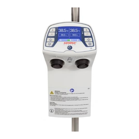
® 6 Product description ASTOPAD Instructions for Use 6.3 Components of the ASTOPAD Control unit Fig. 1 Control unit Designation Description Control panel Operating buttons and temperature displays. For secure attachment of the ASTOPAD control Fastening device unit. Output A (connecting socket) Plug-in connection to connect the applied part. - Page 20 ® ASTOPAD Instructions for Use 6 Product description Applied parts Fig. 2 ASTOPAD COVXXX-NA applied parts Designation Description Example of an ASTOPAD COVXXX-NA applied ASTOPAD COV part Connection cable for connecting to the exten- Connection cable sion connection cable. The attached end cap is closed when no exten- sion connection cable is connected.
-
Page 21: Control Panel
® 6 Product description ASTOPAD Instructions for Use 6.4 Control panel Fig. 3 Control panel No. Designation Description Actual temperature Displays the actual temperature of the applied part A or B Set temperature Displays the selected set temperature of the applied A or B part. -
Page 22: Operating States
® ASTOPAD Instructions for Use 7 Operating states 7 Operating states With a few exceptions, the operating states are described below when only one applied part is connected to output A of the ASTOPAD control unit and is being operated. The description of the operating states applies accordingly to the connection and operation of a second applied part at output B of the ASTOPAD control unit. -
Page 23: On Mode
® 7 Operating states ASTOPAD Instructions for Use 7.2 On mode 7.2.1 On mode (no applied part connected) Control panel Press the Standby button (9) to switch the control unit from Action Standby mode to On mode. • Standby LED (9) goes out. •... - Page 24 ® ASTOPAD Instructions for Use 7 Operating states 7.2.2 On mode (one applied part connected) Control panel Press the Standby button (9) to switch the control unit from Action Standby mode to On mode. • Standby LED (9) goes out. •...
-
Page 25: Heating Mode Output A And/Or B
® 7 Operating states ASTOPAD Instructions for Use 7.3 Heating mode output A and/or B Control panel Action Press the Start button (6) to start the heating process. • The last set temperature (2) is loaded. • Acoustic alarm switches off, and the alarm LED (10) goes out. -
Page 26: Increasing/Decreasing The Set Temperature
® ASTOPAD Instructions for Use 7 Operating states 7.4 Increasing/decreasing the set temperature Control panel Press the Plus (3) / Minus (4) buttons to raise or lower the selected set temperature in 0.5°C increments. Action Confirm the new set temperature by pressing the Start button (6). -
Page 27: Switching Off An Output (A Or B)
® 7 Operating states ASTOPAD Instructions for Use 7.5 Switching off an output (A or B) Control panel Action Press the Stop button (7) to switch off an output. • Start LED (6) goes out. Device • Displays (1) and (2) go off for the output that was switched response off. -
Page 28: Operation Independent Of The Mains (Only For Devices With A Battery)
® ASTOPAD Instructions for Use 7 Operating states 7.6 Operation independent of the mains (only for devices with a battery) After ASTOPAD has reached the set temperature in mains operation, ASTOPAD can be operated independently of the mains for approx. 2 hours using the battery option. - Page 29 ® 7 Operating states ASTOPAD Instructions for Use 7.6.3 Switch to storage/transport mode Control panel Action Hold down Standby button (9) for at least 3 seconds. • Device The Standby LED (9) goes out. • response The display (11) turns off. Battery discharge is reduced.
-
Page 30: Installation
® ASTOPAD Instructions for Use 8 Installation 8 Installation 8.1 Putting into service Before operating this device for the first time: • Inspect the device visually (see section 13.1 Recurrent Tests). • Check the mains voltage (compare the data on the type label with the availa- ble mains voltage). -
Page 31: Getting Started
® 9 Getting started ASTOPAD Instructions for Use For attachment to the medical rail it may be necessary to move the at- tachment device into another position. To do this, release the fixing the screws must be screwed in screws. Once the position is changed, again according to the positioning of the attachment device. - Page 32 ® ASTOPAD Instructions for Use 9 Getting started WARNING Risk of injury! • Overheating of ischemic extremities can occur with the use of the ASTOPAD applied parts. • When applied parts ASTOPAD COV are used as an over-blanket, ensure that they do not obstruct the patient’s field of vision.
-
Page 33: Preparation For Use
® 9 Getting started ASTOPAD Instructions for Use • All ASTOPAD applied parts may be operated only with the ASTOPAD control unit. • All ASTOPAD applied parts should not come in direct skin contact with the patient and must be operated with an intermediate layer between the applied part and the patient. -
Page 34: Starting The Heating Process
® ASTOPAD Instructions for Use 9 Getting started WARNING Risk of injury! If the OR table top is tilted (adjusted through the longitudinal axis), there is a chance that the patient will slip off. The patient must be sufficiently secured against slipping before the OR table top is tilted or otherwise moved out of the horizontal position. -
Page 35: Selecting A New Set Temperature
® 9 Getting started ASTOPAD Instructions for Use WARNING Risk of injury! Do not use ASTOPAD if no visual or audible alarm is activated after switching on via the Standby button (self-test defective). 7. Press the Start button to start the heating process at output A or B with the displayed set temperature. - Page 36 ® ASTOPAD Instructions for Use 9 Getting started Chlorine and peroxides and all other oxidizing disinfectants have a negative impact on the materials of the applied parts, therefore the use of such disinfectants for routine disinfection is not recommended. The lifetime of ASTOPAD components is significantly reduced by these disinfectants.
- Page 37 ® 9 Getting started ASTOPAD Instructions for Use 9.6.3 Control unit 1. Disconnect control unit from mains. 2. Visually inspect control panel and housing from all sides for wear and tear, holes and cracks and other unacceptable deteriorations. Cleaning and disinfecting is possible only when no damage exists! Dam- aged components should not be used.
-
Page 38: Alarms And Troubleshooting
® ASTOPAD Instructions for Use 10 Alarms and troubleshooting 10 Alarms and troubleshooting ASTOPAD does not require continuous supervision by the operator but must be inspected at regular intervals (depending on the condition of the patient). For this, the intended operating location is immediately in front of the control panel of the ASTOPAD control unit. -
Page 39: Low Temperature Alarm A1 (Low Priority Alarm)
® 10 Alarms and troubleshooting ASTOPAD Instructions for Use 10.1 Low temperature alarm A1 (low priority alarm) Control panel The set temperature was reached once. After that, the ac- tual temperature (1) drops by at least 1°C below the set Alarm condition –... -
Page 40: Overheating Alarm A2 (Low Priority Alarm)
® ASTOPAD Instructions for Use 10 Alarms and troubleshooting 10.2 Overheating alarm A2 (low priority alarm) Control panel The set temperature was reached once. After that, the ac- tual temperature (1) rises by at least 1°C above the set Alarm condition temperature (2) and remains below 41°C. -
Page 41: Time Alarm A3 (Low Priority Alarm)
® 10 Alarms and troubleshooting ASTOPAD Instructions for Use 10.3 Time alarm A3 (low priority alarm) Control panel The set temperature (2) is not reached during 60 minutes Alarm condition of uninterrupted heating. • A3 (flashing) appears on the display (5). •... -
Page 42: Overheating Alarm Shut-Off A4 (Medium Priority Alarm)
® ASTOPAD Instructions for Use 10 Alarms and troubleshooting 10.4 Overheating alarm shut-off A4 (medium priority alarm) Control panel Alarm condition The actual temperature (1) is higher than 41°C. • A4 (flashing) appears on the display (5). If both outputs are active, A4 is displayed for both outputs. -
Page 43: Sensor Defect Alarm A5 (Medium Priority Alarm)
® 10 Alarms and troubleshooting ASTOPAD Instructions for Use 10.5 Sensor defect alarm A5 (medium priority alarm) Control panel At least one temperature sensor supplies a value outside Alarm condition the permissible range. • A5 (flashing) appears on the display (5). If both outputs are active, A5 is displayed for both outputs. -
Page 44: Heater Defect Alarm A6 (Medium Priority Alarm)
® ASTOPAD Instructions for Use 10 Alarms and troubleshooting 10.6 Heater defect alarm A6 (medium priority alarm) Control panel Alarm condition The heater of the applied part is defect. • A6 (flashing) appears on the display (5). If both outputs are active, A6 is displayed for both outputs. -
Page 45: Information Messages And Troubleshooting
® 11 Information messages and troubleshooting ASTOPAD Instructions for Use 11 Information messages and troubleshooting 11.1 Battery status (only for devices with a battery) Control panel Information The battery is defect or no original battery is inserted. condition After the Start screen in mains operation and in Standby Device response mode, the display (11, 8) shows the crossed-out battery symbol. -
Page 46: Applied Part Temperature Too High
® ASTOPAD Instructions for Use 11 Information messages and troubleshooting 11.3 Applied part temperature too high Control panel Information The actual temperature (1) is higher than 45°C. condition Device response Display (1) shows H. Possible reasons Actual temperature is outside the display range ►Required ►Allow the applied part to cool. -
Page 47: Brief Overview Of Operating States And Alarms
® 12 Brief overview of operating states and alarms ASTOPAD Instructions for Use 12 Brief overview of operating states and alarms 12.1 Overview of operating states Operating Display Start Alarm Standby Acous- Possible state reasons Output alarm A or B signal Green Yellow... - Page 48 ® ASTOPAD Instructions for Use 12 Brief overview of operating states and alarms Operating Display Start Alarm Standby Acous- Possible state reasons Output alarm A or B signal Green Yellow Blue Actual temperature Set temperature Warm-up phase No applied part Actual temperature connected, or Set temperature...
-
Page 49: Overview Of Alarms
® 12 Brief overview of operating states and alarms ASTOPAD Instructions for Use 12.2 Overview of alarms Start Alarm Standby Acous- Alarm Display Possible reasons Output alarm A or B signal Green Yellow Blue Actual temperature Actual temperature is at least 1°C Low tempera- Set temperature lower than the set... -
Page 50: Maintenance
® ASTOPAD Instructions for Use 13 Maintenance 13 Maintenance To ensure sufficient battery capacity for devices with battery option, the battery should be replaced every 3 years. Replacing the battery is described in section 13.2 Replacing the battery. Furthermore, ASTOPAD does not require preventative maintenance (e.g., ex- change of liquids or components) but recurrent tests in accordance with section 13.1 Recurrent tests. -
Page 51: Replacing The Battery
® 13 Maintenance ASTOPAD Instructions for Use 13.2 Replacing the battery 1. Disconnect the device completely from the mains power supply (by discon- necting the mains plug) 2. Press the Standby button until the Standby LED switches off. 3. Disconnect the mains plug from the device. 4. -
Page 52: Technical Data
® ASTOPAD Instructions for Use 14 Technical data 14 Technical data ASTOPAD DUO310-NA Control unit 100 – 240 VAC Electrical connection 50 – 60 Hz Rated current 110 V = 1,6 A, 240V = 0,8 A Primary fuses 2 x 3.15 A Power consumption max. - Page 53 ® 14 Technical data ASTOPAD Instructions for Use ASTOPAD DUO310-NA Control unit Control of contact surface tem- 32.0 °C to 39.0 °C in 0.5 °C increments perature (Essential Performance ac- Tolerance ± 1.0 °C cording to IEC 80601-2-35) Contact surface temperature ±...
- Page 54 ® ASTOPAD Instructions for Use 14 Technical data ASTOPAD 070-NA 105-NA 150-NA 155-NA 180-NA Power consumption 60 W 115 W 150 W 85 W 150 W Dimensions (mm) approx. approx. approx. approx. approx. Length 1050 1500 1500 1800 Width Height Weight (kg) Connection cable Approx.
-
Page 55: Conformity With International Standards
® 15 Conformity with international standards ASTOPAD Instructions for Use 15 Conformity with international standards Standard Title IEC 60601-1 Medical electrical equipment – Part 1: General ANSI/AAMI ES 60601-1 requirements for basic safety, including essential performance CAN/CSA C22.2 No. 60601-1 Medical electrical equipment –... -
Page 56: Ordering Information And Accessories
® ASTOPAD Instructions for Use 16 Ordering information and Accessories 16 Ordering information and Accessories Ref. -Variant Description Control unit compatible with ASTOPAD COV applied parts ASTOPAD DUO310 control unit, 100-240 VAC, 50-60 Hz, DUO310 -NA Hospital Grade plug Rechargeable battery for ASTOPAD DUO310 control unit (op- 1831.0001 tional) Applied parts... -
Page 57: Guidelines And Manufacturer's Declaration
17 Guidelines and manufacturer’s declaration ® ASTOPAD Instructions for Use 17 Guidelines and manufacturer’s declaration Guidance and manufacturer's declaration - electromagnetic emissions ASTOPAD is intended for use in the electromagnetic environment specified below. The customer or user of the ASTO- PAD should assure that it is used in such an environment. - Page 58 ® 17 Guidelines and manufacturer’s declaration ASTOPAD Instructions for Use Guidance and manufacturer's declaration - electromagnetic immunity The ASTOPAD is intended for use in the electromagnetic environment specified below. The customer or user of the ASTOPAD should assure that it is used in such an environment. Electromagnetic environment –...
- Page 59 17 Guidelines and manufacturer’s declaration ® ASTOPAD Instructions for Use...
Need help?
Do you have a question about the Stihler Electronic ASTOPAD DUO310-NA and is the answer not in the manual?
Questions and answers