
Related Manuals for Gentherm CSZ Blanketrol II 222S


Summary of Contents for Gentherm CSZ Blanketrol II 222S
- Page 1 Operation and Technical Manual Model 222S Hyper-Hypothermia Units Cincinnati Sub-Zero Products, LLC 12011 Mosteller Road Cincinnati, Ohio 45241, U.S.A. www.cszmedical.com...
- Page 2 Operation / Technical Manual BLANKETROL II, Model 222S ® BLANKETROL is a registered trademark of Cincinnati Sub-Zero Products, LLC, Cincinnati, Ohio USA. © Copyright 2017, Cincinnati Sub-Zero Products, LLC. All rights reserved. Manual 57947 Rev. R ECN: M1708-5362 Page 2 of 110...
- Page 3 Operation / Technical Manual BLANKETROL II, Model 222S Symbols and Definitions DECREMENT INCREMENT Read Operation (Decrease (Increase Instructions and Manual Temperature Set Earth (Ground) Temperature) Before Operating Temperature) O / I Automatic Manual AC Voltage OFF / ON Switch Monitor Control Control Only...
- Page 4 Operation / Technical Manual BLANKETROL II, Model 222S ® BLANKETROL OPERATION MANUAL Cincinnati Sub-Zero Products, LLC, reserves the right to make equipment changes and improvements, which may not be reflected in this manual. Warning A physician’s order is required for setting blanket temperature and use of equipment. At least every 20 minutes, or as directed by the physician, check patient’s temperature and skin integrity of areas in contact with blanket;...
- Page 5 Operation / Technical Manual BLANKETROL II, Model 222S Warning Basic static electricity or ESD training should include an introduction to the physics of electrostatic charge, the voltage levels that can occur in normal practice and the damage that can be done to electronic components if equipment is touched by an operator who is electrostatically charged.
- Page 6 Operation / Technical Manual BLANKETROL II, Model 222S Warning Remove the BLANKETROL II from service if the outer casing or membrane control panel is cracked or internal components are exposed. Contact with internal components could result in electric shock or thermal injury to the patient or operator and exposure to sharp edges. ...
- Page 7 Operation / Technical Manual BLANKETROL II, Model 222S CAUTION Federal law restricts this device to sale by or on the order of a physician. Use distilled water only. Do Not Use De-Ionized water. De-Ionized water may cause corrosion to plumbing system components.
-
Page 8: Table Of Contents
Operation / Technical Manual BLANKETROL II, Model 222S TABLE OF CONTENTS TECHNICAL HELP ..............................11 AUTHORIZED EUROPEAN REPRESENTATIVE: ..................... 11 BEFORE YOU CALL FOR SERVICE........................11 IN-WARRANTY REPAIR AND PARTS ....................... 11 RECEIVING INSPECTION ............................ 11 IMPORTANT SAFETY INFORMATION ......................11 SECTION 1. - Page 9 Operation / Technical Manual BLANKETROL II, Model 222S 4-2.5. Replenishing The Reservoir ........................59 4-3. MAINTENANCE OF THE WATER FILTER....................60 4-4. MAINTENANCE OF THE CONDENSER AND GRILL ................61 4-5. MAINTENANCE OF THE BLANKETROL II EXTERIOR – CLEANING INSTRUCTIONS ...... 61 4-6.
- Page 10 Operation / Technical Manual BLANKETROL II, Model 222S TABLE OF FIGURES FIGURE 1- 1: BLANKETROL II, FRONT VIEW ........................15 FIGURE 1-2: BLANKETROL II, RIGHT SIDE VIEW ........................ 17 FIGURE 1- 3: BLANKETROL II, REAR VIEW ......................... 19 FIGURE 1- 4.A.: BLANKETROL II MEMBRANE CONTROL PANEL, ENGLISH ................ 21 FIGURE 1- 4.B.: BLANKETROL II MEMBRANE CONTROL PANEL, SYMBOLS ...............
-
Page 11: Technical Help
Operation / Technical Manual BLANKETROL II, Model 222S TECHNICAL HELP United States and Canada Telephone 1-513-772-8810 Cincinnati Sub-Zero Products, LLC (U.S.) Toll Free 1-800-989-7373 12011 Mosteller Road (U.S.) 24hr Clinical Support 1-513-460-2038 Cincinnati, OH 45241 1-513-772-9119 www.cszmedical.com Authorized European Representative: CEpartner4U, BV Esdoornlaan 13 3951 DB Maarn... -
Page 12: Section 1. Introduction
OPERATION BLANKETROL II, Model 222S OPERATION AND TECHNICAL MANUAL SECTION 1. INTRODUCTION 1-0. GENERAL SAFETY PRECAUTIONS To provide the patient maximum safety during the use of the BLANKETROL II system, a thorough knowledge and understanding of the system, and its correct application and operating use are required. -
Page 13: General Description Of The Blanketrol Ii System
OPERATION BLANKETROL II, Model 222S OPERATION AND TECHNICAL MANUAL 1-2. GENERAL DESCRIPTION OF THE BLANKETROL II SYSTEM INDICATIONS FOR USE The BLANKETROL II Hyper-Hypothermia Temperature Management System is used to lower or to raise a patient’s temperature and/or maintain a desired patient temperature through conductive heat transfer. -
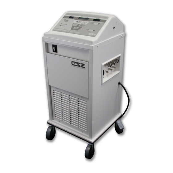
Page 14: Physical Description Of The Blanketrol Ii Unit
OPERATION BLANKETROL II, Model 222S OPERATION AND TECHNICAL MANUAL 1-3. PHYSICAL DESCRIPTION OF THE BLANKETROL II UNIT See Section (7.) for specifications and certifications of the BLANKETROL II. 1-3.1. External Features - Front View The external features in Figure (1-1.) of the BLANKETROL II unit are described as follows: The control panel is composed of pressure sensitive touch switches, six LED indicators, a liquid crystal display, and two LED displays. -
Page 15: Figure 1- 1: Blanketrol Ii, Front View
OPERATION BLANKETROL II, Model 222S OPERATION AND TECHNICAL MANUAL Figure 1- 1: BLANKETROL II, FRONT VIEW Page 15 of 110... -
Page 16: 1-3.2. External Features - Right Side View
OPERATION BLANKETROL II, Model 222S OPERATION AND TECHNICAL MANUAL 1-3.2. External Features - Right Side View The external features in Figure (1-2.) of the BLANKETROL II unit are described as follows: The water flow indicator is a paddle wheel immersed in the path of the circulating water with a window to the outside. -
Page 17: Figure 1-2: Blanketrol Ii, Right Side View
OPERATION BLANKETROL II, Model 222S OPERATION AND TECHNICAL MANUAL FIGURE 1-2: BLANKETROL II, RIGHT SIDE VIEW Page 17 of 110... -
Page 18: 1-3.3. External Features - Rear View
OPERATION BLANKETROL II, Model 222S OPERATION AND TECHNICAL MANUAL 1-3.3. External Features - Rear View The external features in Figure (1-3.) of the BLANKETROL II unit are described as follows: A. The specification label outlines the BLANKETROL II unit's electrical requirements and displays the serial and model numbers of the unit. -
Page 19: Figure 1- 3: Blanketrol Ii, Rear View
OPERATION BLANKETROL II, Model 222S OPERATION AND TECHNICAL MANUAL Figure 1- 3: BLANKETROL II, REAR VIEW Page 19 of 110... -
Page 20: 1-3.4. Expanded Description Of The Blanketrol Ii Membrane Control Panel
OPERATION BLANKETROL II, Model 222S OPERATION AND TECHNICAL MANUAL 1-3.4. Expanded Description Of The BLANKETROL II Membrane Control Panel The membrane control panel as shown in Figure (1-4.A.) for English and (1-4.B.) for Symbols is composed of pressure sensitive touch switches and LED displays. The membrane control panel is divided into the following sections: A. -
Page 21: Figure 1- 4.A.: Blanketrol Ii Membrane Control Panel, English
OPERATION BLANKETROL II, Model 222S OPERATION AND TECHNICAL MANUAL Figure 1- 4.A.: BLANKETROL II MEMBRANE CONTROL PANEL, ENGLISH Figure 1- 4.B.: BLANKETROL II MEMBRANE CONTROL PANEL, SYMBOLS Page 21 of 110... -
Page 22: Required Accessories
OPERATION BLANKETROL II, Model 222S OPERATION AND TECHNICAL MANUAL 1-4. REQUIRED ACCESSORIES Operation of the BLANKETROL II unit requires the use of the blanket(s) designed to circulate warm or cool distilled water, a connecting hose with quick-disconnect male and female fittings and a 400 Series thermistor probe if AUTO CONTROL MODE is to be utilized. -
Page 23: 1-5.3. Cooling System
OPERATION BLANKETROL II, Model 222S OPERATION AND TECHNICAL MANUAL 1-5.3. Cooling System The BLANKETROL II cooling system is composed of a compressor, condenser, condenser fan, an evaporator coil, water temperature control, solenoid valve, hot gas by-pass valve, and two low temperature safety devices. Temperature ranges are described in Section (1- 5.5.). -
Page 24: 1-5.5. Temperature Safety Control System
OPERATION BLANKETROL II, Model 222S OPERATION AND TECHNICAL MANUAL 1-5.5. Temperature Safety Control System The BLANKETROL II unit is designed to carefully measure and control the temperature of the water in the BLANKETROL II equipment. The unit is engineered so that when the temperature of the water in the BLANKETROL II equipment reaches the desired set point temperature, the unit operates between heating and cooling the water in order to maintain the set point temperature. -
Page 25: Section 2. General Preparation Of The Blanketrol Ii System
OPERATION BLANKETROL II, Model 222S OPERATION AND TECHNICAL MANUAL SECTION 2. GENERAL PREPARATION OF THE BLANKETROL II SYSTEM 2-0. INTRODUCTION This section describes the procedures to prepare the BLANKETROL II unit for general use. This entails unpacking the shipment, arranging all the equipment for the first time, and completing a test routine. - Page 26 OPERATION BLANKETROL II, Model 222S OPERATION AND TECHNICAL MANUAL C. Examine the power cord for cuts or exposed wires and the power plug for bent or missing prongs. D. Review Section (1-3.) to identify the features of the BLANKETROL II unit. E.
-
Page 27: 2-2.2. Completing A System Test Routine
OPERATION BLANKETROL II, Model 222S OPERATION AND TECHNICAL MANUAL WARNING Do not by-pass ground lug (230V System). Electrical hazards may result. K. Insert the plug into a properly grounded hospital grade receptacle. 2-2.2. Completing A System Test Routine After arranging the equipment described in Section (2-2.1.), complete this System Test Routine which describes what switches to press and the changes to observe. - Page 28 OPERATION BLANKETROL II, Model 222S OPERATION AND TECHNICAL MANUAL The SETPOINT/ STATUS display shows: SET TEMPERATURE SETPT 37.0°C NOTE (ENGLISH MEMBRANE ONLY): SET POINT may be displayed in Fahrenheit if the operator is in Fahrenheit mode. In order to change from one mode to another, the TEMP SET button must be pressed before the next mode can be set.
- Page 29 OPERATION BLANKETROL II, Model 222S OPERATION AND TECHNICAL MANUAL Check the couplings at the unit and at the blanket for positive connection. J. Press the TEMP SET button. 1. The microprocessor board beeps. 2. The LED in the corner of the switch lights up. 3.
- Page 30 OPERATION BLANKETROL II, Model 222S OPERATION AND TECHNICAL MANUAL CONTROL MODE unless the probe is properly placed on a patient and reading between 30°C – 43.5°C (86°F -110.3°F). P. Press the SILENCE ALARM button. 1. The alarm stops 2. The SETPOINT/ STATUS display continues to flash CHECK PROBE The operator has 5 minutes to correct the problem.
- Page 31 OPERATION BLANKETROL II, Model 222S OPERATION AND TECHNICAL MANUAL 6. The heater or compressor may be activated. 7. The water flow indicator on the right side panel begins to move. The water moves from the unit through the blanket and returns to the unit. 8.
-
Page 32: Unit And Patient Related Precautions
OPERATION BLANKETROL II, Model 222S OPERATION AND TECHNICAL MANUAL lengthwise into the center, 1/3 from the left side and 1/3 from the right side. To drain the water from the reusable blanket simply shut off power to the unit or shut off the operation of the manual or automatic mode and allow the water to drain from the blanket back into the BLANKETROL unit. - Page 33 OPERATION BLANKETROL II, Model 222S OPERATION AND TECHNICAL MANUAL Warning A physician’s order is required for setting blanket temperature and use of equipment. At least every 20 minutes, or as directed by the physician, check patient’s temperature and skin integrity of areas in contact with blanket;...
- Page 34 OPERATION BLANKETROL II, Model 222S OPERATION AND TECHNICAL MANUAL Warning Power interruption will cause the BLANKETROL II to revert to CHECK SET POINT resulting in no therapy to the patient. Follow instructions for desired mode to resume operation. Failure to resume therapy could result in serious injury or death.
- Page 35 OPERATION BLANKETROL II, Model 222S OPERATION AND TECHNICAL MANUAL Warning Use of accessories other than those specified in the Operation and Technical Manual may result in increased electromagnetic emissions or decreased immunity to electromagnetic emissions of the BLANKETROL II unit. This could affect the BLANKETROL II’s compatibility with other electrical equipment.
- Page 36 OPERATION BLANKETROL II, Model 222S OPERATION AND TECHNICAL MANUAL A. A base line recording should be made of vital signs, level of consciousness and responsiveness. B. A dry sheet should be placed between the hyper-hypothermia blanket and the patient when using PLASTI-PAD, or MAXI-THERM Blankets. The MAXI-THERM LITE Blanket and Gelli-Roll pad do not require an interposed sheet.
-
Page 37: Section 3. Operating The Blanketrol Ii Unit
OPERATION BLANKETROL II, Model 222S OPERATION AND TECHNICAL MANUAL SECTION 3. OPERATING THE BLANKETROL II UNIT 3-0. INTRODUCTION This section describes how to operate the BLANKETROL II unit in order to control a patient's temperature. First, collect the equipment and prepare the patient. Second, decide which mode of operation to use. - Page 38 OPERATION BLANKETROL II, Model 222S OPERATION AND TECHNICAL MANUAL H. Lay the hyper-hypothermia blanket flat with the hose routed, without kinks, towards the unit If the blanket is already filled, check that there are no leaks. WARNING Any time water is found leaking into or around the unit, connecting hose, and/or blanket, turn the unit off, disconnect the power cord from its power source, and correct the problem before proceeding.
-
Page 39: Operating The Blanketrol Ii Unit In Auto Control Mode
OPERATION BLANKETROL II, Model 222S OPERATION AND TECHNICAL MANUAL Q. If a top hyper-hypothermia blanket is to be used, follow instructions in step (J). R. Connect the top blanket to the BLANKETROL II unit following the procedure described in Section (2-2.1.). S. - Page 40 OPERATION BLANKETROL II, Model 222S OPERATION AND TECHNICAL MANUAL After arranging the equipment as described in Section (3-1.), proceed as follows: A. Check the placement of the 400 Series probe in or on the patient. B. Insert the 400 Series probe into the probe jack on the right side of the unit. C.
-
Page 41: Operating The Blanketrol Ii Unit In Manual Control Mode
OPERATION BLANKETROL II, Model 222S OPERATION AND TECHNICAL MANUAL Check the water flow indicator to confirm that the water is circulating. J. Touch the hyper-hypothermia blanket to confirm that the blanket is heating/cooling. K. To make any changes in the control settings, press the TEMP SET button and begin again. - Page 42 OPERATION BLANKETROL II, Model 222S OPERATION AND TECHNICAL MANUAL After arranging the equipment as described in Section (3-1.), proceed as follows: A. Press the power switch to the “I” position. 1. The switch lights up. 2. The microprocessor board goes through self-test. 3.
-
Page 43: Operating The Blanketrol Ii Unit In Manual Control Mode With The Addition Of The Patient Probe
OPERATION BLANKETROL II, Model 222S OPERATION AND TECHNICAL MANUAL The BLANKETROL II unit is now operating in MANUAL CONTROL MODE. The operator must continue to monitor the change in the patient's temperature. (Review the suggestions for patient care described in Section (2-4.)). If at any time the SETPOINT/ STATUS display shows a message other than the messages described in MANUAL CONTROL MODE procedures, make the changes indicated by the display and/or consult the list of display messages in Section (3-7.). -
Page 44: Operating The Blanketrol Ii Unit In Monitor Only Mode
OPERATION BLANKETROL II, Model 222S OPERATION AND TECHNICAL MANUAL If at any time the SETPOINT/ STATUS display shows a message other than the messages described in MANUAL CONTROL MODE procedures, make the changes indicated by the display and/or consult the list of display messages in Section (3-7.). If at any time the unit sounds an alarm and the SETPOINT/ STATUS display flashes a message, make the changes as indicated. -
Page 45: Concluding Hyper-Hypothermia Treatment
OPERATION BLANKETROL II, Model 222S OPERATION AND TECHNICAL MANUAL 3-6. CONCLUDING HYPER-HYPOTHERMIA TREATMENT Discontinue therapy upon the order of the physician. Patient's temperature can drift up or down 0.5°C ± 1°C (1°F ± 2°F) after therapy has been discontinued. The drift may be greater if the patient has been shivering and treatment is abruptly discontinued. - Page 46 OPERATION BLANKETROL II, Model 222S OPERATION AND TECHNICAL MANUAL A. During normal operation in MANUAL CONTROL MODE, the SETPOINT/ STATUS display shows the following messages: SETPOINT/ STATUS Function Display Message This message is displayed on the left side of the bottom line and indicates MANUAL that the BLANKETROL II is operating in MANUAL CONTROL MODE.
- Page 47 OPERATION BLANKETROL II, Model 222S OPERATION AND TECHNICAL MANUAL C. During normal operation in MONITOR ONLY MODE the SETPOINT/STATUS display shows the following messages: SETPOINT/ STATUS Function Display Message This message is displayed when the temperature scale is set to Celsius in MONITOR ONLY CELSIUS MONITOR ONLY MODE.
- Page 48 OPERATION BLANKETROL II, Model 222S OPERATION AND TECHNICAL MANUAL This message occurs when the software fails and the water in the BLANKETROL II equipment has reached the high temperature limit of 44.0°C 2°C (111.2°F 3.6°F), activating the independent safety. While this message is displayed, the trouble alarm will sound, and the heater and pump will turn off.
- Page 49 OPERATION BLANKETROL II, Model 222S OPERATION AND TECHNICAL MANUAL This message occurs when EE01 appears in the PATIENT temperature display. Both messages appear when the backup processor does not agree with the primary processor. While both messages are displayed, the trouble alarm will sound, and the heater, compressor and pump will turn off.
- Page 50 OPERATION BLANKETROL II, Model 222S OPERATION AND TECHNICAL MANUAL While in AUTO CONTROL MODE, if the patient probe indicates only a direct short in the probe circuit this message occurs. As this message is displayed, the trouble alarm sounds and the unit shuts down. This alarm can be silenced using the SILENCE ALARM button.
- Page 51 OPERATION BLANKETROL II, Model 222S OPERATION AND TECHNICAL MANUAL This message will be displayed after 500 hours of operation past the last time the (500 hour) counter was reset. The message will only be displayed for 5 seconds at power-up. PM REQUIRED Note: Only qualified Medical Equipment Service Technicians, Certified Biomedical Electronics Technicians, or Certified Clinical Engineers can reset the 500 hour counter after preventative...
-
Page 52: Section 4. General Maintenance Of The Blanketrol Ii System
MAINTENANCE BLANKETROL II, Model 222S OPERATION AND TECHNICAL MANUAL SECTION 4. GENERAL MAINTENANCE OF THE BLANKETROL II SYSTEM 4-0. INTRODUCTION This section describes the general requirements maintenance personnel should complete on a regular basis so that the BLANKETROL II System continues to operate within the manufacturers’... -
Page 53: Test Equipment Required
MAINTENANCE BLANKETROL II, Model 222S OPERATION AND TECHNICAL MANUAL 4-1. TEST EQUIPMENT REQUIRED The following test equipment is required to perform the preventive maintenance/functional check-out procedures: • CSZ's model TFRW 86171 Trimatic (Temperature Tester, Flow Meter, Resistance Tester) - Need Probe Extension Cable #TM-4A (Part # 39005) - Need Hose Assembly #TM-6 (Part # 91802) •... -
Page 54: Figure 4- 1: Maintenance Checklist
MAINTENANCE BLANKETROL II, Model 222S OPERATION AND TECHNICAL MANUAL SUGGESTED PREVENTIVE MAINTENANCE CHECKLIST (Quarterly or when indicated by 500 hour PM notification) BLANKETROL II - Model 222S Hospital Control No. Serial Number Check When Completed External cabinet in good condition. (No unusual dents or missing parts) ... -
Page 55: Maintenance Of The Water Reservoir
MAINTENANCE BLANKETROL II, Model 222S OPERATION AND TECHNICAL MANUAL 4-2. MAINTENANCE OF THE WATER RESERVOIR The dual compartment reservoir holds approximately 2 gallons (7.6 liters) of distilled water that remains in the unit between periods of use. Quarterly, the water reservoir should be drained and replenished. -
Page 56: 4-2.2. Fluid Circuit Disinfection/Dry Storage Procedure (For Circulating Water Units Utilizing Ce Approved Gigasept Ff)
MAINTENANCE BLANKETROL II, Model 222S OPERATION AND TECHNICAL MANUAL Fill the reservoir with warm distilled water. Turn the unit on and circulate per the Chemical Cleaning Circulation (CCC) Chart (above). Note: The duration indicated in the CCC chart is meant to begin when the circulating water reaches the temperature indicated in the CCC chart. -
Page 57: 4-2.3. Fluid Circuit Disinfection/Dry Storage Procedure (For Circulating Water Units Utilizing Ce Approved Maranon H)
MAINTENANCE BLANKETROL II, Model 222S OPERATION AND TECHNICAL MANUAL Fill the reservoir with the appropriate amount of Gigasept FF per the below chart. UNIT Gigasept FF WATER DURATION BLANKETROL II, Model 800 Milliliters 7.6 Liters 15 Minutes 222S Fill the reservoir with the appropriate amount of water per the above chart. Turn the unit on and circulate in Heating Mode @ 38 for 15 minutes. -
Page 58: 4-2.4. Draining The Reservoir
MAINTENANCE BLANKETROL II, Model 222S OPERATION AND TECHNICAL MANUAL Fill the reservoir with the appropriate amount of water per the above chart. Turn the unit on and circulate per the Chemical Cleaning Circulation (CCC) Chart (above). Note: The duration indicated in the CCC chart is meant to begin when the circulating water reaches the temperature indicated in the CCC chart. -
Page 59: 4-2.5. Replenishing The Reservoir
MAINTENANCE BLANKETROL II, Model 222S OPERATION AND TECHNICAL MANUAL WARNING Do not by-pass ground lug (230V System). Electrical Hazards may result. D. Plug the power cord into a properly grounded power outlet. E. Place the power switch to the “I” position. F. -
Page 60: Maintenance Of The Water Filter
MAINTENANCE BLANKETROL II, Model 222S OPERATION AND TECHNICAL MANUAL Proceed with normal operations; always check the water level before starting. 4-3. MAINTENANCE OF THE WATER FILTER The BLANKETROL II circulating system includes a water filter designed to clear the line of any particulate matter as the water is pumped through the system. -
Page 61: Maintenance Of The Condenser And Grill
MAINTENANCE BLANKETROL II, Model 222S OPERATION AND TECHNICAL MANUAL F. Clean the wire mesh and the plastic cap. Be careful not to lose the black O-ring in the rim of the plastic cap. G. Replace the wire mesh in the plastic cap and position the mesh, O-ring and plastic cap. H. -
Page 62: Maintenance Of The Hyper-Hypothermia Blankets
MAINTENANCE BLANKETROL II, Model 222S OPERATION AND TECHNICAL MANUAL 4-6. MAINTENANCE OF THE HYPER-HYPOTHERMIA BLANKETS This section describes the general maintenance for the reusable and disposable blankets. General maintenance tasks include cleaning, draining, and storing the blankets. 4-6.1. Reusable Blankets Cincinnati Sub-Zero reusable blankets are constructed from biocompatible polyurethane/urethane. -
Page 63: Low Limit Safeties Check
MAINTENANCE BLANKETROL II, Model 222S OPERATION AND TECHNICAL MANUAL avoided. Ethylene oxide sterilization does not damage the probe, but gas is highly irritating and is absorbed by the plastic parts. Directions given by the manufacturer of the sterilizer must be closely followed, especially regarding temperature and aeration. -
Page 64: High Limit Safeties Check
MAINTENANCE BLANKETROL II, Model 222S OPERATION AND TECHNICAL MANUAL H. Place a jumper on the test port in the location marked LS. Turn the unit on and monitor the temperature on the water temperature display as the water is cooled. J. -
Page 65: Temperature Accuracy Check
MAINTENANCE BLANKETROL II, Model 222S OPERATION AND TECHNICAL MANUAL H. Place a jumper on the test port in the location marked HS. Turn the BLANKETROL II on and monitor the temperature on the water temperature display as the water is heated. J. -
Page 66: Section 5. Field Repair/Service Of The Blanketrol Ii Unit
FIELD REPAIR/SERVICE BLANKETROL II, Model 222S OPERATION AND TECHNICAL MANUAL SECTION 5. FIELD REPAIR/SERVICE OF THE BLANKETROL II UNIT WARNING Always unplug the unit before accessing internal components during service. Failure to unplug the unit could result in electric shock. ... - Page 67 FIELD REPAIR/SERVICE BLANKETROL II, Model 222S OPERATION AND TECHNICAL MANUAL Figures (5-1.), (6-2.), and (6-4.) highlight the interior components of the BLANKETROL II unit. The internal components referenced in Figure (5-1.) are as follows: A. Upper manifold (return) B. Water temperature sensor C.
-
Page 68: Figure 5- 1: Blanketrol Ii, Exposed Rear View
FIELD REPAIR/SERVICE BLANKETROL II, Model 222S OPERATION AND TECHNICAL MANUAL Figure 5- 1: BLANKETROL II, EXPOSED REAR VIEW Page 68 of 110... -
Page 69: Access To The Interior Of The Blanketrol Ii Unit
FIELD REPAIR/SERVICE BLANKETROL II, Model 222S OPERATION AND TECHNICAL MANUAL 5-1. ACCESS TO THE INTERIOR OF THE BLANKETROL II UNIT All internal operating components are readily accessible by removing the rear enclosure panel, removing the top of the unit, or extending the front storage drawer. NOTE: Drain the reservoir and disconnect the power cord from the power source before removing any part from the unit. -
Page 70: 5-1.3. Removing The Left Side Enclosure Panel
FIELD REPAIR/SERVICE BLANKETROL II, Model 222S OPERATION AND TECHNICAL MANUAL If work is to be done with the microprocessor board, the membrane control panel, or anything related to the top assembly, disconnect the cables from the microprocessor board. Go to Section (5-1.4.). 5-1.3. -
Page 71: 5-1.5. Extending The Front Storage Drawer
FIELD REPAIR/SERVICE BLANKETROL II, Model 222S OPERATION AND TECHNICAL MANUAL C. Locate the following connectors on the microprocessor board and disconnect them by pinching the sides to disengage the connector lock, as required: CONNECTOR J POSITION Red 2-position flow switch connector J9 position Red 9-position connector J8 position... -
Page 72: Replacement Of The Heater
FIELD REPAIR/SERVICE BLANKETROL II, Model 222S OPERATION AND TECHNICAL MANUAL 5-2. REPLACEMENT OF THE HEATER WARNING Always unplug the unit before accessing internal components during service. Failure to unplug the unit could result in electric shock. CAUTION Always drain the BLANKETROL II to a sanitary drain because bio-contaminants may be present in the unit’s water supply. -
Page 73: Replacement Of The Pump Housing
FIELD REPAIR/SERVICE BLANKETROL II, Model 222S OPERATION AND TECHNICAL MANUAL Extend the front storage drawer as described in section (5-1.5). Locate the T-Shaped water filter assembly tucked under the water reservoir. Disconnect the assembly by loosening the two screw clamps (one on each side of the water filter assembly). -
Page 74: Replacement Of The Pump Motor
FIELD REPAIR/SERVICE BLANKETROL II, Model 222S OPERATION AND TECHNICAL MANUAL H. Pull the complete pump housing forward and remove. Insert the replacement housing assembly. Position the housing so that the outlet is pointing upward and the screw holes are aligned. J. - Page 75 FIELD REPAIR/SERVICE BLANKETROL II, Model 222S OPERATION AND TECHNICAL MANUAL G. Using a 7/16" wrench, remove the bolts securing the pump motor to the divider pan in the unit. The bolts are accessible from the front of the unit if the front storage drawer is extended.
-
Page 76: Replacement Of The Flow Switch
FIELD REPAIR/SERVICE BLANKETROL II, Model 222S OPERATION AND TECHNICAL MANUAL 5-6. REPLACEMENT OF THE FLOW SWITCH WARNING Always unplug the unit before accessing internal components during service. Failure to unplug the unit could result in electric shock. CAUTION Always drain the BLANKETROL II to a sanitary drain because bio-contaminants may be present in the unit’s water supply. -
Page 77: Replacement Of The Water Temperature Sensor
FIELD REPAIR/SERVICE BLANKETROL II, Model 222S OPERATION AND TECHNICAL MANUAL 5-7. REPLACEMENT OF THE WATER TEMPERATURE SENSOR WARNING Always unplug the unit before accessing internal components during service. Failure to unplug the unit could result in electric shock. A. Obtain replacement water temperature sensor. CAUTION ... -
Page 78: Replacement Of The Upper And/Or Lower Water Manifolds
FIELD REPAIR/SERVICE BLANKETROL II, Model 222S OPERATION AND TECHNICAL MANUAL 5-8. REPLACEMENT OF THE UPPER AND/OR LOWER WATER MANIFOLDS A. Drain the reservoir as described in Section (4-2.4.). B. Remove the rear enclosure panel as described in Section (5-1.1.). C. Locate the copper water manifold to be replaced. The two manifolds, one lower and one upper, are wrapped in black foam and are secured to the left side (viewed from the rear) of the unit as shown in Figure (5-1.). -
Page 79: Replacement Of The Compressor Starting Capacitor, The Overload Protector, And/Or The Compressor Relay
FIELD REPAIR/SERVICE BLANKETROL II, Model 222S OPERATION AND TECHNICAL MANUAL To replace the upper manifold, continue to Step P. If only replacing the lower manifold, finish with Steps W-X. P. Disconnect the hose at the copper elbow of the upper manifold by loosening the screw clamp. -
Page 80: Replacement Or Cleaning Of The Water Flow Indicator Assembly
FIELD REPAIR/SERVICE BLANKETROL II, Model 222S OPERATION AND TECHNICAL MANUAL F. Using a Phillips screwdriver remove the two screws at the top and bottom of the thermal disc. G. Remove the thermal disc. H. Install the replacement thermal disc. Replace and tighten the two screws. J. -
Page 81: Replacement Of The I/O Power Switch
FIELD REPAIR/SERVICE BLANKETROL II, Model 222S OPERATION AND TECHNICAL MANUAL H. Remove the four remaining Phillips head screws around the face of the water flow indicator. Set the screws to the side. Disassemble the parts of the water flow indicator. Do not lose the large black O-ring. J. -
Page 82: Replacement Of The Water Level Sensor Assembly
FIELD REPAIR/SERVICE BLANKETROL II, Model 222S OPERATION AND TECHNICAL MANUAL H. Connect the wires in the same locations in which they were disconnected. Work the power switch and attached cable to the inside of the unit by pressing together the tension clips on the top and bottom of the switch assembly. J. -
Page 83: Replacement Of The Microprocessor Board And/Or The Membrane Control Panel
FIELD REPAIR/SERVICE BLANKETROL II, Model 222S OPERATION AND TECHNICAL MANUAL 5-14. REPLACEMENT OF THE MICROPROCESSOR BOARD AND/OR THE MEMBRANE CONTROL PANEL WARNING Always unplug the unit before accessing internal components during service. Failure to unplug the unit could result in electric shock. ... -
Page 84: Replacement Of The Beeper Assembly
FIELD REPAIR/SERVICE BLANKETROL II, Model 222S OPERATION AND TECHNICAL MANUAL M. Reposition the top on the unit and reconnect the cables by referencing Section (5-1.2. & 5-1.4.). Reconnect the power wires on the terminal by referencing the wiring diagram, Figure (6-5.) for 115V and Figure (6-6.) for 230V. N. -
Page 85: Leakage Current
FIELD REPAIR/SERVICE BLANKETROL II, Model 222S OPERATION AND TECHNICAL MANUAL 5-17. LEAKAGE CURRENT The BLANKETROL II unit should periodically be checked for Leakage Current prior to general floor use. Using an electrical safety analyzer, measure the electrical Leakage Current under the following conditions: Power ON &... -
Page 86: Refrigerant Check
FIELD REPAIR/SERVICE BLANKETROL II, Model 222S OPERATION AND TECHNICAL MANUAL C. Set the BLANKETROL II unit so that it is COOLING and record the Leakage Current. To set the unit in the Cooling Cycle: 5. Press the power switch to the “I” position. 6. -
Page 87: Troubleshooting Guide
FIELD REPAIR/SERVICE BLANKETROL II, Model 222S OPERATION AND TECHNICAL MANUAL 5-19. TROUBLESHOOTING GUIDE TROUBLESHOOTING GUIDE OBSERVATION POSSIBLE ACTION TO BE TAKEN PROBLEM A. The power switch of the Check that the power cord is BLANKETROL II unit is Unit is unplugged plugged into a properly grounded set on, in “I”... - Page 88 FIELD REPAIR/SERVICE BLANKETROL II, Model 222S OPERATION AND TECHNICAL MANUAL TROUBLESHOOTING GUIDE OBSERVATION POSSIBLE ACTION TO BE TAKEN PROBLEM E. Unit is on, any switch on the membrane control panel is pressed but does not stay set, or when the Membrane switch has Replace membrane control operating mode is...
- Page 89 FIELD REPAIR/SERVICE BLANKETROL II, Model 222S OPERATION AND TECHNICAL MANUAL TROUBLESHOOTING GUIDE OBSERVATION POSSIBLE ACTION TO BE TAKEN PROBLEM Cable from the probe jack to microprocessor board is disconnected, SETPOINT/ Reconnect cable (J8 position on H. The probe from the STATUS display flashes microprocessor board).
- Page 90 FIELD REPAIR/SERVICE BLANKETROL II, Model 222S OPERATION AND TECHNICAL MANUAL TROUBLESHOOTING GUIDE OBSERVATION POSSIBLE ACTION TO BE TAKEN PROBLEM Other than a 400 Series probe was inserted in the Replace with the correct 400 probe jack. Series probe (refer to Figure (6- 9.)).
- Page 91 FIELD REPAIR/SERVICE BLANKETROL II, Model 222S OPERATION AND TECHNICAL MANUAL TROUBLESHOOTING GUIDE OBSERVATION POSSIBLE ACTION TO BE TAKEN PROBLEM N. The unit is operating in one of the three modes, the unit momentarily Low line voltage or power Check line voltage. Reset set point blanks and then the source.
- Page 92 FIELD REPAIR/SERVICE BLANKETROL II, Model 222S OPERATION AND TECHNICAL MANUAL TROUBLESHOOTING GUIDE OBSERVATION POSSIBLE ACTION TO BE TAKEN PROBLEM The Snap Disc high limit Q. Unit is operating in safety device is triggered Replace microprocessor board. AUTOMATIC MODE which shuts down the unit See Section (5-14.).
- Page 93 FIELD REPAIR/SERVICE BLANKETROL II, Model 222S OPERATION AND TECHNICAL MANUAL TROUBLESHOOTING GUIDE OBSERVATION POSSIBLE ACTION TO BE TAKEN PROBLEM Correctly set buttons. See Section Operator error; buttons not (3.). set correctly. Defective pump. Replace the pump. Disengaged quick- Check all fittings for proper fit. disconnect fittings.
- Page 94 FIELD REPAIR/SERVICE BLANKETROL II, Model 222S OPERATION AND TECHNICAL MANUAL TROUBLESHOOTING GUIDE OBSERVATION POSSIBLE ACTION TO BE TAKEN PROBLEM Check for voltage compressor: a. If line voltage is U. Unit is set to operate present. in a control mode. Compressor not running Blanket does not b.
-
Page 95: Section 6. Parts Information
FIELD REPAIR/SERVICE BLANKETROL II, Model 222S OPERATION AND TECHNICAL MANUAL SECTION 6. PARTS INFORMATION 6-0. INTRODUCTION This section outlines information for ordering, shipping and replacing parts of the BLANKETROL II unit, Model 222S. Identification of parts and components are shown in Figures (6-1.) and (6-3.). -
Page 96: Returning Parts Under Warranty
FIELD REPAIR/SERVICE BLANKETROL II, Model 222S OPERATION AND TECHNICAL MANUAL 6-3. RETURNING PARTS UNDER WARRANTY All parts are covered by a two (2) year warranty. To replace parts during the warranty period*, send the part prepaid to: Cincinnati Sub-Zero Products, LLC 12011 Mosteller Road Cincinnati, Ohio 45241 Tel: 1-800-989-7373... -
Page 97: Figure 6-1: Parts List A
FIELD REPAIR/SERVICE BLANKETROL II, Model 222S OPERATION AND TECHNICAL MANUAL INTERNAL EXPLODED - FRONT VIEW Index # Description White Reservoir Lid. Probe Jack Assembly Membrane Control Panel (115V) Membrane Control Panel (230V) Top Assembly (115V) Top Assembly (230V) White Reservoir Lid Assembly (115V) White Reservoir Lid Assembly (230V) Strain Relief Manifold Pan... -
Page 98: Figure 6-2: Blanketrol Ii, Internal Exploded - Front View
FIELD REPAIR/SERVICE BLANKETROL II, Model 222S OPERATION AND TECHNICAL MANUAL Figure 6-2: BLANKETROL II, INTERNAL EXPLODED - FRONT VIEW Page 98 of 110... -
Page 99: Figure 6-3: Parts List B
FIELD REPAIR/SERVICE BLANKETROL II, Model 222S OPERATION AND TECHNICAL MANUAL INTERNAL EXPLODED - REAR VIEW Index # Description Top Assembly (115V) Top Assembly (230V) Patient Probe Label Screw Snap Cap Overflow Drain Hose Barb Drawer Stop - 8-32 x 1/2 Shoulder Bolt Nylon Shoulder Washer Storage Drawer Assembly... -
Page 100: Figure 6-4: Blanketrol Ii, Internal Exploded - Rear View
FIELD REPAIR/SERVICE BLANKETROL II, Model 222S OPERATION AND TECHNICAL MANUAL Figure 6-4: BLANKETROL II, INTERNAL EXPLODED - REAR VIEW Page 100 of 110... -
Page 101: Figure 6- 5: Blanketrol Ii, Electrical Wiring Diagram 115V
FIELD REPAIR/SERVICE BLANKETROL II, Model 222S OPERATION AND TECHNICAL MANUAL Figure 6- 5: BLANKETROL II, ELECTRICAL WIRING DIAGRAM 115V Note: Beeper is located on the board for most devices built before 2nd quarter 2012. Page 101 of 110... -
Page 102: Figure 6- 6: Blanketrol Ii, Electrical Wiring Diagram, 230 V
FIELD REPAIR/SERVICE BLANKETROL II, Model 222S OPERATION AND TECHNICAL MANUAL Figure 6- 6: BLANKETROL II, ELECTRICAL WIRING DIAGRAM, 230 V Note: Beeper is located on the board for most devices built before 2nd quarter 2012. Page 102 of 110... -
Page 103: Figure 6- 7: Blanketrol Ii, Water Circulation Diagram
FIELD REPAIR/SERVICE BLANKETROL II, Model 222S OPERATION AND TECHNICAL MANUAL Figure 6- 7: BLANKETROL II, WATER CIRCULATION DIAGRAM Page 103 of 110... -
Page 104: Figure 6- 8: Blanketrol Ii, Refrigeration Flow Diagram
FIELD REPAIR/SERVICE BLANKETROL II, Model 222S OPERATION AND TECHNICAL MANUAL Figure 6- 8: BLANKETROL II, REFRIGERATION FLOW DIAGRAM Page 104 of 110... - Page 105 FIELD REPAIR/SERVICE BLANKETROL II, Model 222S OPERATION AND TECHNICAL MANUAL ACCESSORIES – BLANKETS Blankets, Pads and Hoses Approved for Use with the BLANKETROL II are listed below. MAXI-THERM Single-Patient Use Blankets Adult or O.R. Table Size (24" x 60") Pediatric Size (22" x 30") Infant Size (12"...
-
Page 106: Figure 6-9: Blanketrol Ii, System Accessories
FIELD REPAIR/SERVICE BLANKETROL II, Model 222S OPERATION AND TECHNICAL MANUAL 4872MS Therma-Temp® Connecting Cable – Molex connection Figure 6-9: BLANKETROL II, SYSTEM ACCESSORIES Page 106 of 110... -
Page 107: Section 7. Specifications And Certifications Of The Blanketrol Ii
FIELD REPAIR/SERVICE BLANKETROL II, Model 222S OPERATION AND TECHNICAL MANUAL SECTION 7. SPECIFICATIONS AND CERTIFICATIONS OF THE BLANKETROL II BLANKETROL II MODEL 222S FEATURES PHYSICAL SAFETY SYSTEM Dimensions: 17"W x 17"D x 37.5"H Maximum High Control Setting: (43.18cm. W x 43.18cm. 42.0°C (107.6°F) x 95.25cm. - Page 108 FIELD REPAIR/SERVICE BLANKETROL II, Model 222S OPERATION AND TECHNICAL MANUAL BLANKETROL II MODEL 222S FEATURES (CONT.) CONTROL SYSTEM (cont’d) CONTROL SYSTEM Display Type: Microprocessor controlled, Lighted "OFF-ON" power switch, Digital LED Read Outs, Alarm Indications, and Mode Indications. Temp. Settings: Water Temp.: 0.1°C (0.1°F) Controller Range:...
-
Page 109: Table 7-1: Guidance And Manufacturer's Declaration – Electromagnetic Emissions
FIELD REPAIR/SERVICE BLANKETROL II, Model 222S OPERATION AND TECHNICAL MANUAL The following tables are presented in fulfillment of the requirements of IEC 60601-1-2 TABLE 7-1: GUIDANCE AND MANUFACTURER’S DECLARATION – ELECTROMAGNETIC EMISSIONS The BLANKETROL II, Model 222S is intended for use in the electromagnetic environment specified below. The customer or the user of the BLANKETROL II, Model 222S should assure that it is used in such an environment. -
Page 110: Ii That Is Not Used For Life Support
FIELD REPAIR/SERVICE BLANKETROL II, Model 222S OPERATION AND TECHNICAL MANUAL TABLE 7-3: GUIDANCE AND MANUFACTURER’S DECLARATION – ELECTROMAGNETIC IMMUNITY FOR BLANKETROL II THAT IS NOT USED FOR LIFE SUPPORT The BLANKETROL II, Model 222S is intended for use in the electromagnetic environment specified below. The customer or the user of the BLANKETROL II, Model 222S should assure that it is used in such an environment. -
Page 111: Worldwide Order Placement
FIELD REPAIR/SERVICE BLANKETROL II, Model 222S OPERATION AND TECHNICAL MANUAL TABLE 7-4: RECOMMENDED SEPARATION DISTANCES BETWEEN PORTABLE AND MOBILE RF COMMUNICATIONS EQUIPMENT AND THE BLANKETROL II, MODEL 222S The BLANKETROL II, Model 222S is intended for use in an electromagnetic environment in which radiated RF disturbances are controlled. - Page 113 Cincinnati Sub-Zero Products, LLC 12011 Mosteller Road Cincinnati, OH 45241 Toll Free: 1-800-989-7373 Fax: (513) 772-9119 www.cszmedical.com...
Need help?
Do you have a question about the CSZ Blanketrol II 222S and is the answer not in the manual?
Questions and answers