Table of Contents
Advertisement
Quick Links
Owner's Manual & Safety Instructions
Save This Manual
operating, inspection, maintenance and cleaning procedures. Write the product's serial number in the
back of the manual (or month and year of purchase if product has no number). Keep this manual and the
receipt in a safe and dry place for future reference.
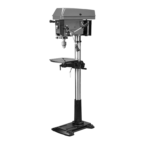
17" VARIABLE-SPEED
DRILL PRESS
email our technical support at: productsupport@harborfreight.com
When unpacking, make sure that the product is intact
and undamaged. If any parts are missing or broken,
please call 1-888-866-5797 as soon as possible.
©
Copyright
2023 by Harbor Freight Tools
No portion of this manual or any artwork contained herein may be reproduced in
any shape or form without the express written consent of Harbor Freight Tools.
Diagrams within this manual may not be drawn proportionally. Due to continuing
improvements, actual product may differ slightly from the product described herein.
Tools required for assembly and service may not be included.
Keep this manual for the safety warnings and precautions, assembly,
Visit our website at: http://www.harborfreight.com
®
. All rights reserved.
232012E-B
read this material before using this product.
Failure to do so can result in serious injury.
SaVe tHiS ManUaL.
23k
58783
Advertisement
Table of Contents

Subscribe to Our Youtube Channel
Related Manuals for Harbor Freight Tools Bauer 232012E-B


Summary of Contents for Harbor Freight Tools Bauer 232012E-B
- Page 1 No portion of this manual or any artwork contained herein may be reproduced in Failure to do so can result in serious injury. any shape or form without the express written consent of Harbor Freight Tools. Diagrams within this manual may not be drawn proportionally. Due to continuing SaVe tHiS ManUaL.
-
Page 2: Table Of Contents
table of contents Important Safety Information ...... 2 Maintenance and Servicing ....... 12 Specifications ..........5 Parts List and Assembly Diagram....14 Setup - Before Use ........5 Warranty ............ 16 Operating Instructions ........ 8 WarninG SyMBOLS anD DeFinitiOnS This is the safety alert symbol. It is used to alert you to potential personal injury hazards. - Page 3 General tool Safety Warnings (continued) 10. WEAR PROPER APPAREL. Do not wear 17. USE RECOMMENDED ACCESSORIES. loose clothing, gloves, neckties, rings, bracelets, Consult the owner’s manual for recommended or other jewelry which may get caught in moving accessories. The use of improper accessories parts.
-
Page 4: Drill Press Safety Warnings
If unreadable or missing, contact 5. The included chuck key is specially designed Harbor Freight Tools for a replacement. to be self-ejecting, reducing the risk of ejecting 13. Avoid unintentional starting. at high speed. Only use the included chuck Prepare to begin work before turning on the tool. -
Page 5: Specifications
Spindle Stroke 4.7″ (120mm) This product complies with 21 CFR 1040.10 and 1040.11 Spindle Taper Distributed by Harbor Freight Tools, Calabasas, CA, 58783 Chuck Capacity 5/8″ (16mm) Manufacture Date: ___________, ______ caUtiOn! Use of controls or adjustments or performance of procedures other than those specified herein may result in hazardous exposure. - Page 6 Setup - Before Use (continued) assembly column to Base 1. Place Column Base (141) onto the Base (136). column Base (141) 2. Place Bolts (142) in Column Base and Base. 3. Tighten Bolts. Base (136) Bolt (142) table to table Support table (96) 1.
- Page 7 installing Speed Handle Speed Handle (92) 1. Install Speed Handle (92) by threading into opening on left side of Drill Press. Feed Handles/Bars Feed Bar Thread Feed Bars (67) into Feed Bar Seat (68) Feed Bar Seat (68) and tighten them. Handles (66) Feed Bar (67) installing/removing the chuck...
-
Page 8: Operating Instructions
Operating instructions read the entire iMpOrtant SaFety inFOrMatiOn section at the beginning of this manual including all text under subheadings therein before set up or use of this product. tool Set Up tO preVent SeriOUS inJUry FrOM acciDentaL OperatiOn: turn the power Switch of the tool off and unplug the tool from its electrical outlet before performing any procedure in this section. - Page 9 changing Drill Speed 1. Refer to table below to determine appropriate 2. To adjust drill speed, simply raise or lower the Speed speed for drill size being used. Handle (91) until LED display shows desired RPM. note: Drill press must be running note: If Belt is too long to be properly during speed change.
-
Page 10: Workpiece And Work Area Set Up
Workpiece and Work area Set Up 1. Designate a work area that is clean and well-lit. 7. IF THE MATERIAL IS IRREGULARLY SHAPED and The work area must not allow access by children cannot be laid flat on the table, it should be securely or pets to prevent distraction and injury. - Page 11 General Operating instructions 1. Bring drill bit down with Feed Knob to where hole is 7. To lock Drill Press in OFF position, remove to be drilled. safety key from Power Switch and store Make minor workpiece alignment adjustments. key in a safe place until next use. 2.
-
Page 12: Cleaning, Maintenance, And Lubrication
Maintenance and Servicing procedures not specifically explained in this manual must be performed only by a qualified technician. tO preVent SeriOUS inJUry FrOM acciDentaL OperatiOn: turn the power Switch of the tool off and unplug the tool from its electrical outlet before performing any procedure in this section. -
Page 13: Troubleshooting
Laser adjustment WarninG! tO preVent SeriOUS 5. Gently rotate Laser Housing until both inJUry: Do not stare directly into laser Laser lines intersect at the indentation. beam. Please observe all safety rules: 6. Tighten both set screws. a. Never aim the beam at a person or an object other than the workpiece. -
Page 14: Parts List And Assembly Diagram
parts List and assembly Diagram parts List part Description part Description part Description Motor Plate Bearing V-Belt Work Table Hex Socket Screw Spring Washer Drift Key Upper Medium Wheel Motor Rod 2 Socket Screw Lower Medium Wheel Motor Rod 1 Laser Medium Wheel Washer... - Page 15 assembly Diagram record product’s Serial number Here: note: If product has no serial number, record month and year of purchase instead. note: Some parts are listed and shown for illustration purposes only, and are not available individually as replacement parts. Specify UPC 193175446565 when ordering parts. 58783 For technical questions, please call 1-888-866-5797.
-
Page 16: Please Read The Following Carefully
Limited 90 Day Warranty Harbor Freight Tools Co. makes every effort to assure that its products meet high quality and durability standards, and warrants to the original purchaser that this product is free from defects in materials and workmanship for the period of 90 days from the date of purchase.
Need help?
Do you have a question about the Bauer 232012E-B and is the answer not in the manual?
Questions and answers