Nortel Meridian 1 Installation, Operation And Maintenance Manual
Application helios system 600/48
Hide thumbs
Also See for Meridian 1:
- Features and services description (1162 pages) ,
- Description, installation, and maintenance (128 pages) ,
- Installation and configuration manual (398 pages)

Related Manuals for Nortel Meridian 1


Summary of Contents for Nortel Meridian 1
- Page 1 167-9021-111 Meridian 1 applications - HELIOS System 600/48 Description, Installation, Operation and Maintenance Manual P0815188 Standard 2.0 March 1997 - FOURTH REVIEW...
- Page 3 Meridian and the Advanced Power Systems and Nortel logos are trademarks of Northern Telecom Meridian 1 - HELIOS System 600/48 Description, Installation, Operation & Maintenance Manual...
-
Page 5: Publication History
Issue 2.0 Standard. This document includes revisions according to the customer request. November 1995 Issue 1.0. Standard. This document includes revisions according to comments on the previous issue 1.0 and is now rated Standard. Meridian 1 - HELIOS System 600/48 Description, Installation, Operation & Maintenance Manual P0815188... - Page 6 6 Publication history 167-9021-111 Standard 2.0 March 1997...
-
Page 7: Table Of Contents
NT6C25FF Front Access Controller 23 Mechanical 23 Electrical 23 NT5C12AC power shelf (MPS150) 23 Mechanical 23 Electrical 24 NT5C07AC 50 A Switch Mode Rectifier 24 Mechanical 24 Electrical 26 Meridian 1 - HELIOS System 600/48 Description, Installation, Operation & Maintenance Manual P0815188... - Page 8 Wiring GMT fuses 57 Connecting loads to the FACBR-50 59 Connections at the Meridian 1 equipment 62 Electrical connections to Meridian 1 with "OLD" (internal) NT7D10 PDU 67 System Monitor connections 69 Installing the rectifiers in the power shelves 70...
- Page 9 Figure 12 AC connections in the power shelf (from the rear of the framework) 40 Figure 13 Connections for the signal cable on the signal interface circuit card 44 Meridian 1 - HELIOS System 600/48 Description, Installation, Operation & Maintenance...
-
Page 10: List Of Tables
(right side) 53 Figure 23 Wiring details of the LVD relay and contactor 54 Figure 24 Typical safety frame ground layout in a Meridian 1 installation Figure 25 Cross section of a circuit breaker kit - installed 57 Figure 26... - Page 11 Procedure 13 Installing the rectifiers 71 Procedure 14 Start-up, verification and adjustments of the NT5C07AC rectifiers 72 Procedure 15 Start-up, verification and adjustments of the NT6C25FF front access controller 75 Meridian 1 - HELIOS System 600/48 Description, Installation, Operation & Maintenance...
- Page 12 12 Contents Procedure 16 Wiring and testing the remote activation of the LVD contactor Procedure 17 Meridian 1 system powering and verification 78 Procedure 18 Final verification and adjustments of the NT5C07AC rectifiers Procedure 19 Connecting the batteries to the FACEP-600 83...
-
Page 13: About This Document
How this manual is organized This manual is divided into six parts: • Introduction • Specifications • Installation and start-up • Operation • Maintenance • Appendixes Meridian 1 - HELIOS System 600/48 Description, Installation, Operation & Maintenance Manual P0815188... - Page 14 14 About this document 167-9021-111 Standard 2.0 March 1997...
-
Page 15: Introduction
AC ON AC ON HVSD HVSD HVSD HVSD HVSD HVSD FAIL FAIL FAIL ST UP ST UP ST UP VOUT+ VOUT- VOUT+ VOUT- VOUT+ VOUT- MAIN BAY (NT6C32AD) Meridian 1 - HELIOS System 600/48 Description, Installation, Operation & Maintenance Manual P0815188... -
Page 16: Description
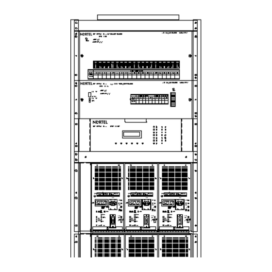
16 Introduction Description The System 600/48 power plant is a positive ground, –48 V dc power plant with a maximum capacity of 600 A. The main bay (NT6C32AD) provides up to 300 A capacity. It consists of one 58 inch high framework (61 in. with the cover kit extension) equipped with one FACEP-600 front access common equipment panel, one NT6C25FF front access controller, one FACBR-50 front access circuit breaker panel equipped with 10 x 30 A circuit breakers, and two NT5C12AC modular power shelves... -
Page 17: Equipment Applications
Many existing SL-1 and Meridian SL-1 cabinet types are also supported for Meridian 1 upgrade situations where the NT6C32AD/AE System 600/48 may be used to provide power to both the new Meridian 1 and the existing equipment. Stand alone SL-1 cabinet applications are also supported. - Page 18 18 Introduction THIS PAGE IS INTENDED TO BE BLANK 167-9021-111 Standard 2.0 March 1997...
-
Page 19: Overall Power Plant Specifications
Electromagnetic interference (EMI) compliance The equipment contained in the power plant complies with the specifications of FCC, Part 15, Subpart B for class A equipment and CSA 108.8 Class A. Meridian 1 - HELIOS System 600/48 Description, Installation, Operation & Maintenance Manual P0815188... -
Page 20: Esd Immunity
20 Specifications ESD immunity No equipment damage or malfunction shall occur when electrostatic discharge (ESD) voltages of severity level 2 and 4, as specified by IEC-801-2, are applied to exposed parts of the power plant. Environmental Operating • Temperature: 32° to 122°F (0° to +50°C) •... -
Page 21: Individual Component Specifications
FRONT ACCESS COMMON EQUIPMENT PANEL NT6C18CB REL ( ) LVD BYP SER NO ( ) MAX FUSE 15 A MAX FUSE BLOCK 50 A NORM UNIT LVD BYP AMPS LOAD Meridian 1 - HELIOS System 600/48 Description, Installation, Operation & Maintenance... -
Page 22: Electrical
22 Specifications Electrical • Charge battery bus bar capacity: 700 A • Discharge battery busbar capacity: 600 A • Battery return busbar capacity: 700 A • Shunt rating (50 mV drop): 800 A • LVD contactor capacity: 800 A Other equipment •... -
Page 23: Nt6C25Ff Front Access Controller
Width Weight 13.00 in. 14.25 in. 23.00 in. 33 lb 330 mm 362 mm 584 mm 15 kg Each MPS150 shelf can support up to three (3) plug-in rectifiers. Meridian 1 - HELIOS System 600/48 Description, Installation, Operation & Maintenance... -
Page 24: Electrical
24 Specifications Figure 5 Front view of the MPS150 Power Shelf (shown empty) AC INPUT POSITION 1 POSITION 2 POSITION 3 Electrical The total output capacity of a shelf is 150 A. Each rectifier position provides interconnection points for AC input (208 or 240 V nominal), DC output (–48 V nominal) and control and alarm signals. - Page 25 FOR CONTINUED PROTECTION AGAINST RISK OF FIRE,REPLACE ONLY WITH SAME TYPE AND RATING OF FUSE. 250 v CA/AC VOLT HELIOS Rectifier 50/48 VOLT CC/DC AC ON HVSD HVSD FAIL ST UP VOUT+ VOUT- Meridian 1 - HELIOS System 600/48 Description, Installation, Operation & Maintenance...
-
Page 26: Electrical
26 Specifications Electrical Table 9 50 A rectifier electrical specifications Input Voltage Nominal 208/240 V ac single phase, 47-63 Hz. Input Rating: Voltage Range 176 to 264 V ac. Input Current 15 A nominal at 208 V ac input and –56 V dc, 50 A output Rating: Recommended Two 20A fuses (one on each line) or two 20A circuit... -
Page 27: Installation And Start-Up
3/8 in. (10 mm) • screwdriver, flat blade, 3/32 in. (2 mm) • electricians knife • wire stripper • Allen key set • hammer drill Meridian 1 - HELIOS System 600/48 Description, Installation, Operation & Maintenance Manual P0815188... -
Page 28: Precautions And Preparation
28 Installation and start-up • 8 mm (5/16 in.) and 19 mm (3/4 in.) concrete bits • Hilti HSD6 and HSD10 anchor setting tools • cable cutters (up to 750 MCM) • linesmen pliers • open end and box end wrench sets •... - Page 29 Prevent equipment failure To optimize service life of this equipment, it must be located in a dry, well ventilated room, with no obstructions in front of the ventilation openings. Meridian 1 - HELIOS System 600/48 Description, Installation, Operation & Maintenance Manual P0815188...
-
Page 30: Receiving The Material
30 Installation and start-up Receiving the material The NT6C32AD main bay and the NT6C32AE supplementary bay are shipped as preassembled power frames. The rectifiers are shipped separately. Other material such as cable, wire, connecting material, fuses, mounting hardware, etc. are also shipped separately. Upon receiving an NT6C32AD or NT6C32AE framework, or both, remove the packaging and inspect the equipment for damage. - Page 31 Install the floor anchoring hardware. Refer to Figure 8 for the anchoring assembly stackups. Torque the bolts to 25 ft-lb (33 Nm) for standard installations. Torque the bolts to 50 ft-lb (67 Nm) for seismic installations. —end— Meridian 1 - HELIOS System 600/48 Description, Installation, Operation & Maintenance Manual P0815188...
- Page 32 32 Installation and start-up Figure 7 Floor anchor pattern with typical isolation pad 1.30 19.80 Secondary Location for the Anchor Primary Location for the Anchor Figure 8 Floor anchor assemblies and isolation pad installation Threaded rod Hex nut Threaded rod Flat washer Hex nut Belleville washer...
-
Page 33: Installing The Cover Kit Extension
Note: The face plate of the cover extension and the top 2-1n. panel on the framework can be removed later for ease of access while installing the distribution wiring. Meridian 1 - HELIOS System 600/48 Description, Installation, Operation & Maintenance Manual P0815188... -
Page 34: Installation Of The System 600/48 Supplementary Bay
34 Installation and start-up Installation of the System 600/48 supplementary bay IMPORTANT NOTE Specific requirements apply to the supplementary bay Whether it is added to a System 600/48 main bay, to an MPP600, or to a QCA13 power cabinet, the supplementary bay must be installed within 20 cable feet of the main bay. -
Page 35: Power Plant Wiring
Improper wiring can cause personal injury and equipment damage. Verify for proper polarity of the battery leads before connecting them to the power plant, by clearly identifying the positive lead and the negative lead. Meridian 1 - HELIOS System 600/48 Description, Installation, Operation & Maintenance Manual P0815188... -
Page 36: Ac Input Wiring For The Rectifiers
36 Installation and start-up AC input wiring for the rectifiers The System 600/48 frameworks are totally front access. For this purpose, they are provided with an AC duct which allows AC wiring of the rectifiers from the top with rigid or flexible conduit, or from the bottom with flexible conduit. The AC leads are then run through the enclosed duct along the side of the bay and connected to the rectifier shelves as shown in Procedure 3 and Figures 9 and 10. - Page 37 Then, make the power and ground connections at the AC service panel. Replace the blank panels at the front of the shelves until the rectifiers are to be installed. Replace the AC duct cover. —continued— —end— Meridian 1 - HELIOS System 600/48 Description, Installation, Operation & Maintenance Manual P0815188...
-
Page 38: Figure 9 Ac Duct Cabling
38 Installation and start-up Figure 9 AC duct cabling Conduit Building AC upply Pull box AC service (if required) panel AC duct Cover kit extension for DC cabling System 600/48 Front Figure 10 AC connections in the power shelf (from the AC duct) FRAME GRD 167-9021-111 Standard 2.0 March 1997... -
Page 39: Ac Wiring From The Rear Of The Framework
Make the power and ground connections at the AC service panel. Replace the blank panels at the front of the shelves until the rectifiers are to be installed. —end— Meridian 1 - HELIOS System 600/48 Description, Installation, Operation & Maintenance Manual P0815188... -
Page 40: Dc Cabling
40 Installation and start-up Figure 11 AC wiring at the rear of the framework Strain relief connector Power Flexible shelf conduit Tightening Isolation bushings screw Strain relief connector FR GRD Power Rectifier shelf shelf chassis ENLARGED VIEW SIDE VIEW OF SYSTEM 600/48 Figure 12 AC connections in the power shelf (from the rear of the framework) FRAME GRD... -
Page 41: Cabling A System 600/48 Supplementary Bay To A Main Bay Or Cabinet
System 600/48 supplementary bay and a System 600/48 main bay. Note 11: The following Procedure assumes that the physical installation and the AC wiring were completed for both System 600/48 bays. Meridian 1 - HELIOS System 600/48 Description, Installation, Operation & Maintenance Manual P0815188... - Page 42 42 Installation and start-up Note 12: Although this Procedure can be completed with the System 600/48 powered up, it is recommended that the System 600/48 be powered down and the AC power removed, if possible. Procedure 5 Cabling a System 600/48 supplementary bay to a System 600/48 main bay Step Action On the NT6C14PE signal interface circuit card, ensure that the six...
- Page 43 “L” bracket on the right rear busbar (–DISCH BAT) in the FACBR-50 panel in the main bay. Refer to Figure 17. —end— —continued— Meridian 1 - HELIOS System 600/48 Description, Installation, Operation & Maintenance Manual P0815188...
-
Page 44: Figure 13 Connections For The Signal Cable On The Signal Interface Circuit Card
44 Installation and start-up Figure 13 1 Connections for the signal cable on the signal interface circuit card NT6C14PE SIGNAL INTERFACE CIRCUIT CARD CONNECTIONS INSIDE THE NT6C25FF CONTROLLER J1 = 1 RECT. J2 = 2 RECT. J3 = 3 RECT. J4 = 4 RECT. - Page 45 BOTTOM RIGHT END CORNER IN THE MPS150 SHELF (SHOWN EMPTY) FLS LEAD FROM LOWER POWER SHELF POSITION 3 POSITION 3 SHIELD CONNECTION FLS LEAD CONNECTION OUTPUT CONNECTIONS Meridian 1 - HELIOS System 600/48 Description, Installation, Operation & Maintenance Manual P0815188...
- Page 46 46 Installation and start-up Figure 16 Connecting the rectifier shelves inside the FACEP-600 panel CHARGE BATTERY BATTERY BATTERY RETURN BUSBAR (-48V) CONNECTIONS BUSBAR (+) CHARGE BUSBARS – IN THE FACEP-600 PANEL FROM THE RECTIFIER SHELVES Figure 17 Mounting of and connecting to the “L” brackets inside the FACBR-50 panel TO THE BATTERY TO THE –48 V DISCH RETURN BUSBAR...
-
Page 47: Cabling A System 600/48 Supplementary Bay To A Qca13 Power Cabinet
GRD terminal in both power shelves (see Figure 15) and the CHG+ busbar in the QCA13 cabinet (see Figure 18 - use empty positions). —continued— Meridian 1 - HELIOS System 600/48 Description, Installation, Operation & Maintenance Manual P0815188... - Page 48 (upper right side of cabinet). Refer to Figure 18. Note 1: The +BAT RTN busbar is also referred to as the GROUND WINDOW in the Meridian 1 documentation. Using the bolts and “L” brackets supplied with the supplementary bay, install one bracket on each of the right rear busbar (+BAT RTN) and left rear busbar (–DISCH BAT) inside the FACBR-50 panel on the...
- Page 49 2 is wired 3 is wired 4 is wired 5 is wired 6 is wired 7 is wired 8 is wired 9 is wired 10 is wired Meridian 1 - HELIOS System 600/48 Description, Installation, Operation & Maintenance Manual P0815188...
-
Page 50: Cabling A System 600/48 Supplementary Bay To A Mpp 600 Power Cabinet
50 Installation and start-up Table 10 Connecting assignment of P0743899 signal cable From System 600/48 J2412 controller in Color Designation supplementary bay the QCA13 cabinet P8-1 N.C. Green P8-2 TSA 39 Black RG + P8-3 TSA 37 RC – P8-4 N.C. - Page 51 Using the appropriate lugs, connect the two 2/0 cables labelled (–) between the –48 terminal in both power shelves (see Figure 15) and the –CHG BAT busbar in the MPP600 power cabinet (see Figure 20). —continued— Meridian 1 - HELIOS System 600/48 Description, Installation, Operation & Maintenance Manual P0815188...
- Page 52 52 Installation and start-up Procedure 7 Cabing a System 600/48 supplementary bay to an MPP600 power cabinet Step Action Run two 2/0 cables labelled (+) and two 2/0 cables labelled (–) between the FACBR-50 panel in the System 600/48 supplementary bay and the +BAT RTN and –DISCH BAT busbars on top of the MPP600 power cabinet.
- Page 53 – DISCH CONTACTOR DISTRIBUTION BREAKERS LVD RELAY PART OF CEP KIT PANEL – CHG (RIGHT SIDE) PART OF 8" REAR COVER (RIGHT SIDE) RECTIFIER SIGNAL INTERFACE CARD Meridian 1 - HELIOS System 600/48 Description, Installation, Operation & Maintenance Manual P0815188...
-
Page 54: Connecting The Safety Frame Ground And Battery/Logic Return Reference Leads
54 Installation and start-up Figure 23 Wiring details of the LVD relay and contactor GREY –DISCH CONTACTOR BLACK TO BR BUSBAR RELAY –CHG CONNECTION BY INSTALLER NT6C14PE RECTIFIER YELLOW INTERFACE CARD IN 8" PARTIAL VIEW REAR COVER INSIDE CEP PANEL AND 8"... - Page 55 COMMON BLANK PANEL EQUIPMENT BLANK PANEL CONTROLLER BATTERY RACK POWER SHELF POWER SHELF FRAME GROUND POWER SHELF POWER SHELF SYSTEM 600/48 SYSTEM 600/48 MAIN BAY SUPPLEMENTARY BAY Meridian 1 - HELIOS System 600/48 Description, Installation, Operation & Maintenance Manual P0815188...
-
Page 56: Connecting The Meridian 1 Loads
56 Installation and start-up Connecting the Meridian 1 loads The System 600/48 uses FACBR-50 breaker type distribution panels. The breakers used with the System 600/48 are midtrip. A standard breaker will send an alarm every time it is shut off. A midtrip breaker will not send an alarm when it is manually shut off. -
Page 57: Wiring Gmt Fuses
Figure 26 below to connect loads to GMT fuses. CAUTION Protect the equipment against electrical damage. Do not exceed the 50 A total rating for the NT6C18PE GMT circuit pack. Meridian 1 - HELIOS System 600/48 Description, Installation, Operation & Maintenance Manual P0815188... - Page 58 58 Installation and start-up Procedure 9 Wiring GMT fuses Step Action Ensure that all fuses are removed from the GMT fuse block. Remove the front panel of the FACEP-600. Use a flat blade screwdriver to loosen the 1/4 turn captive screws. Make battery and battery return connections at the terminal strips.
-
Page 59: Connecting Loads To The Facbr-50
This arrangement is such that five wires, 2 BAT, 2 BR and 1 LRTN enter the top of the plant through one knockout in the conduit/bushings plate. Meridian 1 - HELIOS System 600/48 Description, Installation, Operation & Maintenance Manual P0815188... - Page 60 60 Installation and start-up The circuit breaker and the battery return lugs are the two hole type. The holes are for 1/4 in. diameter studs or screws. The center to center spacing between the holes is 1.00 inch. Since the load connections are close to each other, it is recommended to use shrink tubing on all battery and ground connections in the FACBR-50 panel.
- Page 61 LRTN 1 Figure 28 Details of the battery return (BR) and logic return (LRTN) connections on the DISCH BAT RTN busbar ( + ) BUSBAR ANGLES LUGS Meridian 1 - HELIOS System 600/48 Description, Installation, Operation & Maintenance Manual P0815188...
-
Page 62: Connections At The Meridian 1 Equipment
Refer to Power engineering NTP (553-3001-152) for information about calculating the size and number of power conductors required. If conduit is required, power wiring to the Meridian 1 pedestal can be installed in flexible or rigid metallic conduit. Up to seventeen 3/4 in. and up to seven 1-1/4 in. - Page 63 0-200 FT 200 + FT Note 1: Two 30 A feeds are typically adequate for a full Meridian 1 column of four modules (five wires total - two 30 A feed pairs plus one logic return with all wires of the same gauge).
- Page 64 64 Installation and start-up Figure 29 System 600/48 to Meridian 1 pedestal power connections BR BUSBAR (COMMON RETURN) –48 V DC BUSBAR CB COMMON FEED BUSBAR ANGLE 30 A CIRCUIT BREAKERS TOP VIEW OF FACBR-50 DISTRIBUTION PANEL NT7D67CB DC PDU...
- Page 65 Note: SENSE and TRIP off of the SL-1 cabinet (QCA type) will not be connected, this function is now managed by the System 600/48 from the batteries. Figure 30 Pedestal rear view showing the NT7D67CB DC PDU Meridian 1 - HELIOS System 600/48 Description, Installation, Operation & Maintenance Manual P0815188...
- Page 66 NT 7D67CB LRTN UNIT ASSY BLO CB0 CB1 CB2 CB3 Cable-tie saddle Cable restraint bar Cable-tie saddle Electrical connections to Meridian 1 with “OLD” (internal) NT7D10 PDU Note: Conduit is required for the NT7D10 PDU 167-9021-111 Standard 2.0 March 1997...
-
Page 67: Electrical Connections To Meridian 1 With "Old" (Internal) Nt7D10 Pdu
Four wires are labelled BAT0 through BAT3. • Four wires are labelled RTN0 through RTN3. • One wire is labelled FGRD. • The remaining wire is labelled LRTN. —continued— Meridian 1 - HELIOS System 600/48 Description, Installation, Operation & Maintenance Manual P0815188... - Page 68 68 Installation and start-up Procedure 11 Electrical connections to the Meridian 1 pedestal Step Action Note: If a junction box is used, the connections in Steps 3 through 5 apply to the junction box, rather than the pedestal. Install the number of power wires required from the System 600/48 to the pedestal or junction box.
-
Page 69: System Monitor Connections
—continued— —end— System Monitor connections This Procedure applies only to the CPU0 pedestal of the Meridian 1 system connecting to the System 600/48. When connecting a System 600/48 to the Meridian 1, an NT8D46AV (32 ft), BV (64 ft), or CV (100 ft) cable is required to extend the LF alarm, DCON 0 (RFA alarm), and DCON 1, 2 and 3 (MAJOR alarm) signals from the System 600/48 to the System monitor. -
Page 70: Installing The Rectifiers In The Power Shelves
70 Installation and start-up Procedure 12 System monitor connections (see Table 12) Step Action Verify that a 22 AWG strap is connected between the positive (ground) charge busbar and TB2-4. Verify that 22 AWG straps are connected between TB2-4 and TB4-6, as well as between TB4-6 and TB5-1. -
Page 71: Start-Up Overview
0.70 V dc above float • High voltage shut down -57.0 V dc • Current limit 52.5 A • Start-up delay 4 seconds • Load sharing slope load sharing method Meridian 1 - HELIOS System 600/48 Description, Installation, Operation & Maintenance Manual P0815188... -
Page 72: Start-Up, Verification And Adjustments Of The Rectifiers
72 Installation and start-up CAUTION Float voltages. Equalizes voltages and Alarm adjustments of the rectifiers and the plant controller should be made according to the battery manufacturer’s installation guide, or damage to the battery may result. Appendix E lists the suggested voltage and alarm level settings based on the type of batteries being used. - Page 73 56.0 V and -56.1 V. Turn the FLT ADJ potentiometer counter clockwise two turns. If necessary, reset the rectifier by toggling the AC circuit breaker to OFF and back to ON. —continued— Meridian 1 - HELIOS System 600/48 Description, Installation, Operation & Maintenance Manual P0815188...
- Page 74 74 Installation and start-up Procedure 14 Start-up and adjustments of the NT5C07AC rectifiers Step Action Float voltage adjustment Place the FLT/QL switch on the rectifier being adjusted in the FLT position. Set the DC circuit breaker of the rectifier being adjusted to ON and verify that only the AC ON indicator is lit.
-
Page 75: Start-Up, Verification And Adjustments Of The Front Access Controller
CAL position. The switch may be held operated with a piece of tape or a rubber band. —continued— Meridian 1 - HELIOS System 600/48 Description, Installation, Operation & Maintenance Manual P0815188... - Page 76 Setting of these switches to any other position will vary the sense voltage for the rectifiers, causing the rectifiers to supply a higher voltage output which may damage the Meridian 1 equipment. Note 2: Equalization may be triggered manually by the EQL switch or automatically by the Low Float alarm.
-
Page 77: Remote Activation Of The Lvd Contactor
The following Procedure describes the required wiring and the method to verify the activation of the LVD contactor. Meridian 1 - HELIOS System 600/48 Description, Installation, Operation & Maintenance Manual P0815188... -
Page 78: Meridian 1 System Powering And Verification
When the ground signal is present on pin 3 of TB1 on the LVD control and bypass card, the LVD contactor opens, disconnecting the power to the Meridian 1. The LVD contactor remains open as long as the ground is present on pin 3. When the ground is removed from pin 3, the LVD contactor closes, again providing power to the Meridian 1. -
Page 79: Final Verification And Adjustments Of The Nt5C07Ac Rectifiers
A SYSLOAD can now be performed, according to NTP 553-3001-210 System Installation Procedures. After the Meridian 1 is operational, the System 600/48 interface to the System Monitor may be verified by inducing fault conditions as follows: - Turn one rectifier off to generate a minor alarm. - Page 80 80 Installation and start-up Procedure 18 Final verification and adjustments of the NT5C07AC rectifiers Step Action Load share verification Place the meter selector switch on all rectifiers to the AMP position. Verify that the curent readings on all rectifiers are within 10% of each other.
- Page 81 Repeat steps 9 thru 12 as necessary until the rectifiers are balanced and the proper equalize voltage is obtained. Operate the controller EQL switch to RESET and verify that the rectifiers switch back to float mode. —end— —continued— Meridian 1 - HELIOS System 600/48 Description, Installation, Operation & Maintenance Manual P0815188...
-
Page 82: Connecting The Batteries To The Facep-600
82 Installation and start-up Connecting the batteries to the FACEP-600 CAUTION Protect the equipment against electrical damage. The conductors from the batteries to the positive and negative charge busbars should be connected only after all other conductor installation on the System 600/48 has been completed and verified. - Page 83 System 600/48. Refer to Figure 34. Apply a torque of 15 ft-lb (20 Nm). Connect the battery return (+) and the battery (–) leads at the batteries. Apply the torque value recommended by the battery manufacturer. —end— Meridian 1 - HELIOS System 600/48 Description, Installation, Operation & Maintenance Manual P0815188...
- Page 84 84 Installation and start-up Figure 34 Battery connections in the FACEP-600 TO BATTERY STRINGS BATTERY CHARGE BATTERY RETURN ( - 4 8 V ) TO RECTIFIER SHELVES WITH LUGS SMALLER THAN 535 MCM TO BATTERY STRINGS BATTERY RETURN (+) BATTERY CHARGE (-48V) TO RECTIFIER SHELVES WITH 535 AND 750 MCM LUGS 167-9021-111 Standard 2.0 March 1997...
-
Page 85: Installation Of The Front Panels Of The System 600/48
1/4 turn screws on the lower cover. The lower cover overlaps the upper cover thus securing both covers. Figure 35 Installation of the front cover panels on the main bay SYSTEM 600/48 LVD BYP Meridian 1 - HELIOS System 600/48 Description, Installation, Operation & Maintenance Manual P0815188... - Page 86 86 Installation and start-up THIS PAGE IS INTENDED TO BE BLANK 167-9021-111 Standard 2.0 March 1997...
-
Page 87: Operation
(-43 VDC), typically after an extended AC power outage, to prevent complete discharge, and therefore damage to the batteries. The automatic reconnect feature monitors the battery voltage and Meridian 1 - HELIOS System 600/48 Description, Installation, Operation & Maintenance Manual P0815188... -
Page 88: Nt6C12Fb Front Access Circuit Breaker Panel (Facbr-50)
88 Operation ensures that the load will be reconnected as soon as the commercial AC power is restored and the DC voltage is at least -50 V, without operator intervention. The LVD may be wired with a remotely located "kill switch" to provide a means to cut the battery off from the loads in emergencies (refer to IS6C32AD/AE). - Page 89 Used to activate or deactivate the equalize function. HVSR Used to reset the high voltage shutdown circuit. Used to cancel the audible alarm signal. Used to test all the visual indicators on the controller. Meridian 1 - HELIOS System 600/48 Description, Installation, Operation & Maintenance...
-
Page 90: Inner Side Of The Front Panel
90 Operation Potentiometers Eleven (11) potentiometers for the adjustment of alarm and control functions thresholds as shown in the following Table. Table 15 Potentiometers High Voltage Shutdown HVSD High Voltage Alarm Low Voltage Alarm High Float Alarm Low Float Alarm Low Voltage Disconnect Battery On Discharge Plant Voltage Adjust... -
Page 91: Back Plane Circuit Pack
Visual indicators The DS1 and DS2 light emitting diodes are used for presence of voltage and polarity indication at the time of cabling and testing the panel at the factory. Meridian 1 - HELIOS System 600/48 Description, Installation, Operation & Maintenance... - Page 92 92 Operation Connectors Sixteen (16) connectors for connectorized internal wiring as shown in the following Table. Table 19 Connectors J1 to J12 Rectifier control and signal interface. J13 to J15 Interface with front panel control board. Interface with HVSDR circuit pack. Alarm transmitting relays Relays with form C contacts are used to transmit alarms as shown in the following Table.
-
Page 93: Nt5C12Ac Power Shelf (Mps150)
A 3-1/2 digit output current meter displays either the current or the voltage at the sense point. Finally, an internal logic power supply provides the various voltages required by the logic circuitry and the cooling fan unit. Meridian 1 - HELIOS System 600/48 Description, Installation, Operation & Maintenance... -
Page 94: Description Of The Front Panel Control And Display Features
94 Operation Description of the front panel control and display features The front panel is provided with switches, potentiometers and test jacks used to select and adjust the operating parameters of the rectifier, an LED display and LED indicators used for the indication of the operating and alarm conditions, and circuit breakers used for the protection and control of the input and output supplies. -
Page 95: Start-Up Delay
124 seconds [all 4 dip switches to the left]. If a different start-up delay time is required, see Figure 37 to choose the new setting. Meridian 1 - HELIOS System 600/48 Description, Installation, Operation & Maintenance... -
Page 96: Circuit Breakers
96 Operation Figure 37 Start-up delay switches DELAY DELAY DELAY DELAY DELAY DELAY DELAY DELAY DELAY DELAY DELAY DELAY NOTE: 1 = ON, 0 = OFF These switches correspond to the bottom four switches on the six position DIP switch accessible on the front, with DELAY DELAY DELAY... -
Page 97: Description Of The Operating, Monitoring, Measurement, Protection And Control
DC breaker is ON or OFF. A 5 kOhm resistor is placed in series with the -48 V lead to prevent damage due to short circuit at the jack terminals. Meridian 1 - HELIOS System 600/48 Description, Installation, Operation & Maintenance... - Page 98 98 Operation Local float/equalize control The rectifier is equipped with a momentary Float/Equalize switch. When the switch is operated to the EQL position, the rectifier changes to the equalize mode and boosts the output voltage to the value set by the EQL ADJ potentiometer located above the switch.
- Page 99 The load sharing mode is normally set at the time of installation and setup by the SLS/FS switches located on the front panel (lower right side) of the rectifier. The rectifier is factory set to slope sharing mode. Meridian 1 - HELIOS System 600/48 Description, Installation, Operation & Maintenance...
-
Page 100: Rear Interface
100 Operation Slope load sharing (SLS): When the SLS/FS switch is set to the SLS position, load sharing is achieved due to a –300 mV slope on the output voltage from no load to full load on the rectifier. This mode should be used when rectifiers from different vendors are used which are not all equipped with the forced load sharing feature. - Page 101 This connector is designed so that the DC and frame ground connections are established before the AC connections. Figure 39 shows the rectifier to shelf power interface connections. Figure 39 Power interface connections RECTIFIER SHELF CONNECTOR FR GRD Meridian 1 - HELIOS System 600/48 Description, Installation, Operation & Maintenance...
- Page 102 102 Operation Signal interface connector This connector is used to interface all the control, alarm and monitoring signals with the power shelf which, in turn, interfaces these with the controller. The control inputs are activated by a ground (BAT RTN) signal. The alarms are extended by relay contacts and are isolated from each other and from the rectifier chassis.
-
Page 103: Routine Maintenance
Table 26 provides a list of the problems which may occur on the NT6C32AD/ AE System 600/48, along with their possible causes. Blown fuses and tripped circuit breakers should always be investigated before utilizing this table. Meridian 1 - HELIOS System 600/48 Description, Installation, Operation & Maintenance Manual P0815188... - Page 104 104 Maintenance CAUTION Precautions shall be taken to avoid service interruptions. When working on a live power plant, the Low Voltage Disconnect contactor should be prevented from tripping. To do so, set the NORM/BYP switch to “BYP” on the FACEP-600 panel. Table 26 Fault diagnosis Fault symptom...
- Page 105 Alarm wire connected on wrong pin on circuit breaker RFA lamp lit (yellow) • One rectifier has failed RFA lamp lit (red) • Two or more rectifiers have failed —continued— Meridian 1 - HELIOS System 600/48 Description, Installation, Operation & Maintenance Manual P0815188...
-
Page 106: Addition / Replacement Procedures
106 Maintenance Table 26 Fault diagnosis Fault symptom Possible causes ACO lamp lit • ACO switch has been operated during an alarm condition which is still ongoing EQL lamp lit • The equalize has been activated Rectifiers not load sharing • Share mode incorrectly set •... -
Page 107: Replacing A Rectifier
Notify the Alarm Center of the end of the procedure. —end— Addition or replacement of a battery string For new installations, go to Step 5. For replacements, proceed from Step 1 as follows: Meridian 1 - HELIOS System 600/48 Description, Installation, Operation & Maintenance Manual P0815188... - Page 108 108 Maintenance CAUTION This procedure implies that all or part of the batteries will be momentarily taken out of service. This work should then be completed during reduced traffic hours and/or with a diesel generator backup available to ensure no loss of service during a possible AC outage. If more than one string is to be replaced, replace only one string at a time and do not disconnect the next string before the previous one is reconnected.
-
Page 109: Addition Or Replacement Of A Distribution Circuit Breaker
Connect the load cable to the new circuit breaker. Reinstall the front cover. Operate the circuit breaker to ON and verify for power at the load. —end— Meridian 1 - HELIOS System 600/48 Description, Installation, Operation & Maintenance Manual P0815188... - Page 110 110 Maintenance THIS PAGE IS INTENDED TO BE BLANK 167-9021-111 Standard 2.0 March 1997...
-
Page 111: Appendix A: Schematics
Appendix A: Schematics Meridian 1 - HELIOS System 600/48 Description, Installation, Operation & Maintenance Manual P0815188... - Page 112 112 Appendix A: Schematics 167-9021-111 Standard 2.0 March 1997...
-
Page 113: Appendix B: Recommended Spares
GMT fuses as required for the FACEP-600 panel • 30 A mid-trip circuit breaker kit as required for the FACBR-50 panel A0601247 • NT6C12PB alarm circuit pack A0408933 Meridian 1 - HELIOS System 600/48 Description, Installation, Operation & Maintenance Manual P0815188... - Page 114 114 Appendix B: Recommended spares 167-9021-111 Standard 2.0 March 1997...
-
Page 115: Appendix C: Customer Service Addresses
Meridian 1 Customers are required to contact their nearest Meridian 1 representative for service on the equipment covered in the present manual. However, in emergency situations, if unablbe to reach your Meridian 1 representative, contact one of the following service centers for service on power equipment. - Page 116 116 Appendix C: Customer service addresses This page is left blank intentionally. 167-9021-111 Standard 2.0 March 1997...
- Page 117 C a n a d a H 8 S 1 B 6 Stre C o u n t r y : Zi p : Name: RETURN ADDRESS: Meridian 1 - HELIOS System 600/48 Description, Installation, Operation & Maintenance Manual P0815188...
- Page 118 Please help us better meet your needs by completing and returning the following questionnaire. Your replies give us valuable insight into the effectiveness of our documentation. Document title: Meridian 1 applications - System 600/48, NTP 167-9021-111. Job function: Are you a Northern Telecom employee?
-
Page 119: Appendix D: Applicable Documents
MPP600 Modular Power System 167-2191-200 J2412A power equipment cabinet (QCA13) 169-2071-501 NT5C07AC 50 A rectifier 553-3001-120 Meridian 1 installation planning 553-3001-152 Meridian 1 power engineering 553-3001-210 Meridian 1 system installation Meridian 1 - HELIOS System 600/48 Description, Installation, Operation & Maintenance Manual P0815188... - Page 120 120 Appendix D: Applicable documents 167-9021-111 Standard 2.0 March 1997...
-
Page 121: Appendix E: Voltage Levels For Rectifiers And Controllers
Battery types This Appendix addresses the two most often used battery types; the conventional calcium and antimony lead acid battery, and the valve regulated lead acid (VRLA) battery. Meridian 1 - HELIOS System 600/48 Description, Installation, Operation & Maintenance Manual P0815188... -
Page 122: Charging Characteristics
122 Appendix E: Voltage levels for rectifiers and controllers In the conventional lead acid battery cell, when battery charging approaches its final stage, the charging current is consumed solely for electrolytic decomposition of water in the electrolyte, resulting in generation of oxygen and hydrogen gas which escape in the atmosphere. - Page 123 Power plant voltage and alarm settings The suggested power plant operational limits are shown in Table 29. These limits may be readjusted to suit different operational limits due to load or environmental requirements. Meridian 1 - HELIOS System 600/48 Description, Installation, Operation & Maintenance...
-
Page 124: Features
124 Appendix E: Voltage levels for rectifiers and controllers Table 29 Power plant voltage and alarm settings Qty. Alarms Controls Battery type HVSD FLOAT cells Conventional 52.08 52.5 +0.7 43.5 50.5 Absolyte II 52.21 52.6 +0.7 43.5 50.5 Liberty 52.21 Chloride 52.44 Eagle Picher... -
Page 125: List Of Terms
ABSF alarm battery supply fuse alternating current ACEG AC equipment ground alarm cut-off assembly drawing adjust American wire gaging battery on discharge battery return bypass calibrate Meridian 1 - HELIOS System 600/48 Description, Installation, Operation & Maintenance Manual P0815188... - Page 126 126 List of terms common equipment panel current limit common CONT control Canadian Standard Association direct current electromagnetic interference equalize electrostatic discharge EXTBR external battery return fuse alarm FABR front access battery return FACB front access circuit breaker (panel) FAFP front access fuse panel forced sharing ground...
- Page 127 LR or LRTN logic return lamp test low voltage low voltage alarm low voltage disconnect LVDR low voltage disconnect reconnect major minor Meridian 1 - HELIOS System 600/48 Description, Installation, Operation & Maintenance Manual P0815188...
- Page 128 128 List of terms modular power shelf normally closed NORM normal plant rectifier control RECT rectifier remote equalize rectifier failure alarm sense shunt slope load sharing single point ground temporary release test Underwriter Laboratories volt 167-9021-111 Standard 2.0 March 1997...
- Page 129 List of terms 129 wiring diagram water vapor pressure Meridian 1 - HELIOS System 600/48 Description, Installation, Operation & Maintenance Manual P0815188...
- Page 130 130 List of terms 167-9021-111 Standard 2.0 March 1997...
- Page 131 Total pages in document = 31 Family Product Manual Contacts Copyright Legal statements Trademarks DocNum Application DocRelease Date Publishing statement...
- Page 132 Meridian and the Advanced Power Systems and Nortel logos are trademarks of Northern Telecom Publication number: 167-9021-111 Product release: Standard Document release: 2.0...
Need help?
Do you have a question about the Meridian 1 and is the answer not in the manual?
Questions and answers