Table of Contents
Advertisement
Quick Links
ACR
OM−03507−OM03
August 27, 2007
INSTALLATION, OPERATION,
AND MAINTENANCE MANUAL
WITH PARTS LIST
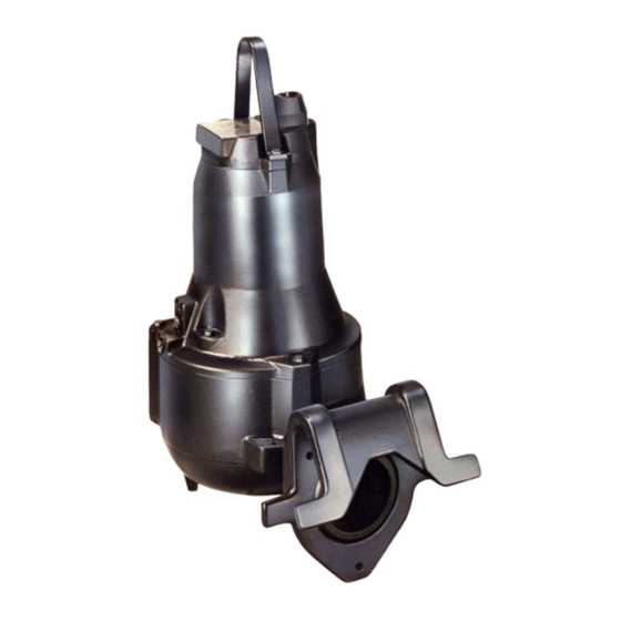
SUBMERSIBLE PUMPS
MODELS
JSV4D60−E14 200/3, 230/3, 460/3, 575/3
JSV4E60−E17 200/3, 230/3, 460/3, 575/3
THE GORMAN-RUPP COMPANY D MANSFIELD, OHIO
www.grpumps.com
D
GORMAN-RUPP OF CANADA LIMITED
ST. THOMAS, ONTARIO, CANADA
Printed in U.S.A.
e
Copyright by the Gorman-Rupp Company
Advertisement
Table of Contents

Related Manuals for GORMAN-RUPP PUMPS JSV4D60-E14 200/3


Summary of Contents for GORMAN-RUPP PUMPS JSV4D60-E14 200/3
- Page 1 OM−03507−OM03 August 27, 2007 INSTALLATION, OPERATION, AND MAINTENANCE MANUAL WITH PARTS LIST SUBMERSIBLE PUMPS MODELS JSV4D60−E14 200/3, 230/3, 460/3, 575/3 JSV4E60−E17 200/3, 230/3, 460/3, 575/3 THE GORMAN-RUPP COMPANY D MANSFIELD, OHIO www.grpumps.com GORMAN-RUPP OF CANADA LIMITED ST. THOMAS, ONTARIO, CANADA Printed in U.S.A.
- Page 2 Register your new Gorman-Rupp pump online at www.grpumps.com Valid serial number and e-mail address required. RECORD YOUR PUMP MODEL AND SERIAL NUMBER Please record your pump model and serial number in the spaces provided below. Your Gorman-Rupp distributor needs this information when you require parts or service. Pump Model: Serial Number:...
-
Page 3: Table Of Contents
OM−03507 J SERIES TABLE OF CONTENTS INTRODUCTION ......PAGE I−1 SAFETY − SECTION A . - Page 4 J SERIES OM−03507 MAINTENANCE AND REPAIR − SECTION E PAGE E−1 PUMP MODELS ........PAGE E−1 PARTS LISTS: Pump Model...
-
Page 5: Introduction
J SERIES OM−03507 INTRODUCTION Thank You for purchasing a Gorman-Rupp pump. Read this manual carefully to learn how to safely Gorman-Rupp of Canada Limited install and operate your pump. Failure to do so 70 Burwell Road could result in personal injury or damage to the St. -
Page 6: Safety − Section A
OM−03507 J SERIES SAFETY − SECTION A This information is specific to the Gorman-Rupp J Series Submersible pumps listed on the cover and in MAINTENANCE AND REPAIR − SECTION E. It applies throughout this manual to the instruc- 230/460 Volt versions of this pump are tions contained in the pages which follow. - Page 7 J SERIES OM−03507 chains or cables are wrapped around taken before attempting to open or ser- the pump to lift it, make certain that they vice the pump; otherwise, injury or are positioned so as not to damage the death could result. pump, and so that the load will be bal- 1.
-
Page 8: Installation − Section B
OM−03507 J SERIES INSTALLATION − SECTION B Review all SAFETY information in Section A. d. Check that amperes, phase, voltage, and Hertz indicated on the motor name plate match the ratings on the control box. This section is intended only to summarize recom- mended installation practices for this pump. - Page 9 J SERIES OM−03507 16024 FIGURE B−1. PUMP DIMENSIONS PAGE B − 2 INSTALLATION...
-
Page 10: Pump Motor Specifications
OM−03507 J SERIES Pump Motor Specifications (104_F) ambient, plus 115_C (239_F) temperature rise. The motor furnished with this pump is a 60 Hz., Squirrel Cage, Induction Start, G-R Frame Size No. 4; Class F Insulation Rated 155_C (311_F) , 40_C See Table B−1 for motor specifications. -
Page 11: Electrical Connections
J SERIES OM−03507 No suction piping is required in a standard sub- TABLE B-2. MOTOR VOLTAGE LIMITS merged operation. NOMINAL PHASE MINIMUM MAXIMUM VOLTAGE VOLTAGE VOLTAGE The optional elbow/baseplate is drilled for a 3−inch or 4−inch discharge flange connection. Either hose or rigid pipe may be used to make dis- charge connections. -
Page 12: Conductor Identification
OM−03507 J SERIES If the test circuit does not close there is a defect in Ground the control box in accordance with the in- the cable or motor which must be corrected. structions accompanying it. Refer to FIGURE B−2, and connect the pump mo- tor cable to the control box. - Page 13 J SERIES OM−03507 Wiring Diagrams (EXTERNAL WIRING) Motor connection diagrams for dual voltage mo- tors are shown in FIGURE B−3. Power cable con- 200/575 VOLTS nection diagrams for 200 and 575 Volt motors are shown in FIGURE B−4. The complete schematic wiring diagrams for the motor are shown in FIG- URE B−5.
- Page 14 OM−03507 J SERIES FIGURE B−5. INTERNAL MOTOR WIRING INSTALLATION PAGE B − 7...
-
Page 15: Liquid Level Devices
J SERIES OM−03507 Liquid Level Devices phragm which flexes with changes in liquid level, thus activating an enclosed miniature Optional controls available from Gorman-Rupp switch. may provide a means to automatically regulate the Bulb (Float) Type: a bulb raises or lowers liquid level. -
Page 16: Operation − Section C
OM−03507 J SERIES OPERATION − SECTION C PERFORMANCE CURVES NOTE The curves apply to standard production models. If In the performance curves which follow, perform- your pump serial number is followed by an N", ance is based on 70_F (21_C) clear water at sea your pump is not a standard production model. - Page 17 J SERIES OM−03507 PERFORMANCE CURVE − JSV4E60−E17 PAGE C − 2 OPERATION...
-
Page 18: Control Box And Optional Controls
OM−03507 J SERIES Review all SAFETY information in Section A. pump is operated against a closed discharge valve for an extended period of time. Follow the instructions on all tags, labels and The submersible motor is cooled by the liquid be- decals attached to the pump. -
Page 19: Starting, Stopping, And Operational Checks
J SERIES OM−03507 automatically. To avoid the hazards of an unexpected motor start-up, do not at- tempt to handle or service the pump un- less all power to the motor has been While checking impeller rotation, secure shut off at the control box; otherwise, the pump to prevent the motor power serious personal injury could result. -
Page 20: Cold Weather Preservation
OM−03507 J SERIES shown on the Pump Performance pump from the wet well and dry it thoroughly. Run the pump for two or three minutes to dry the inner Curves. walls. Check the pump for overheating. Overheating can occur if the pump is misapplied, required to start If the pump does freeze while it is out of the liquid, repeatedly, if the control box fails to provide over- submerge it until thawed;... -
Page 21: Troubleshooting − Section D
OM−03507 J SERIES TROUBLESHOOTING − SECTION D Review all SAFETY information in Section A. NOTE Many of the probable remedies listed in the TROU- BLESHOOTING CHART require use of electrical test instruments; for specific procedures, see ELECTRICAL TESTING at the end of the chart. TROUBLESHOOTING CHART TROUBLE POSSIBLE CAUSE... -
Page 22: Electrical Testing
J SERIES OM−03507 TROUBLESHOOTING CHART (cont’d) TROUBLE POSSIBLE CAUSE PROBABLE REMEDY (CONT.) INSUFFICIENT LIQUID IN WET WELL. STOP PUMP UNTIL LIQUID LEVEL RISES. MOTOR RUNS, BUT DOES NOT IMPELLER ROTATING IN WRONG DI− CHECK IMPELLER ROTATION (SEE SEC− DELIVER RATED RECTION. -
Page 23: Motor And Power Cable Continuity
OM−03507 J SERIES wrong terminals may damage the motor Normal amperage values are listed in Table 1, Section B; these values apply only when the and/or control devices. voltage at the site is the normal voltage listed. Equipment Motor and Power Cable Continuity Set the megohmmeter at R x 1 scale and zero-ba- Ammeter To check AC Voltage... -
Page 24: Maintenance And Repair − Section E . Page
OM−03507 J SERIES MAINTENANCE AND REPAIR − SECTION E MAINTENANCE AND REPAIR OF THE WEARING PARTS OF THE PUMP WILL MAINTAIN PEAK OPERATING EFFICIENCY PUMP MODELS THE FOLLOWING PUMP MODELS, FROM SERIAL NO. 1258055 UP , ARE COVERED IN THIS SECTION. JSV4D60−E14 200/3, 230/3, 460/3, 575/3 JSV4E60−E17 200/3, 230/3, 460/3, 575/3 IF YOUR PUMP SERIAL NUMBER IS FOLLOWED BY AN N", YOUR PUMP IS NOT A STANDARD... -
Page 25: Sectional Drawing
J SERIES OM−03507 PARTS PAGE SECTIONAL DRAWING FIGURE E−1. PUMP MODEL ASSEMBLY PAGE E − 2 MAINTENANCE AND REPAIR... - Page 26 OM−03507 J SERIES PARTS LIST − FIGURE E−1 ITEM PART NAME PART NUMBER MOTOR ASSEMBLY (200V) 26825−137 MOTOR ASSEMBLY (230V) 26825−171 MOTOR ASSEMBLY (460V) 26825−170 MOTOR ASSEMBLY (575V) 26825−073 : IMPELLER (JSV4D60) 26823−858 : IMPELLER (JSV4E60) 26823−857 : SHAFT KEY 26824−173 SCREW 26824−379...
- Page 27 J SERIES OM−03507 SECTIONAL DRAWING FIGURE E−2. MOTOR ASSEMBLIES PAGE E − 4 MAINTENANCE AND REPAIR...
-
Page 28: Parts Lists
OM−03507 J SERIES MOTOR ASSEMBLIES PARTS LIST ITEM PART NAME PART ITEM PART NAME PART NUMBER NUMBER ROTOR AND SHAFT 26825−228 CONNECTOR SET (200V) 26825−426 203 : UPPER BALL BEARING 26823−732 CONNECTOR SET (230V) 26823−426 UPPER RETAINING RING 26824−217 CONNECTOR SET (460V) 26823−427 UPPER SUPPORT RING 26824−302... -
Page 29: Pump And Motor Disassembly
J SERIES OM−03507 PUMP AND MOTOR DISASSEMBLY AND REASSEMBLY Review all SAFETY information in Section A. assembly, be careful not to mar the surface or tapered end of the shaft. PUMP END DISASSEMBLY Do not attempt to service the pump end Except as noted, all references are to FIGURE and/or motor assemblies unless all E−1. -
Page 30: Lower Seal Removal
OM−03507 J SERIES If no further disassembly is required, refer to IN- DISASSEMBLY for upper seal replacement. SPECTION AND CLEANING, followed by PUMP END REASSEMBLY. 4. Refer to INSPECTION AND CLEANING before reassembling the pump end components. Lower Seal Removal PUMP END REASSEMBLY All references are to FIGURES E−2 and E−3. -
Page 31: Installing Impeller
J SERIES OM−03507 Installing Impeller Upper Seal Removal NOTE References are to FIGURE E−1. Use caution in Step 1, tension on the seal clamp springs will be released. 1. Check the impeller (5) for broken vanes, cracks, or excessive wear. Replace as neces- sary. -
Page 32: Motor Cover Removal And Disassembly
OM−03507 J SERIES 207) by hand to check for roughness or bind- lation sleeve (414) and insulation plate (427) ing; replace as necessary. are free parts. 4. Remove the motor cover (230). 2. To remove the upper bearing (203), lightly oil the upper end of the rotor/shaft (201) and pull 5. -
Page 33: Bearings
J SERIES OM−03507 flammable. Use them only in a well− the bearings are in operation. Coat external surfaces with light oil to ease reassembly. ventilated area free from flame, sparks, and excessive heat. Read and follow all 4. Cover the bearings with clean cloth to keep ex- precautions printed on solvent contain- ternal surfaces free of all dirt and foreign mate- ers. -
Page 34: Motor Reassembly
OM−03507 J SERIES Cleaning Seal Assemblies quired other than at either end, replace the entire cable. NOTE If the cable inlet (236), cable clamp (238), and rub- Seal faces are precision-finished and sub- ber seal (235) have been moved or removed, lubri- ject to wear patterns which cannot be re- cate the motor cable (234) to ease installation. -
Page 35: Bearing Installation
J SERIES OM−03507 mate to local humidity levels before check- ing and adjusting the clearance as follows. See FIGURE E−4, and install the switch in a simple bell circuit or other test circuit. Use a Refer to the wiring diagrams in INSTAL- feeler gauge to check clearance between the LATION, Section B, when connecting all expander and switch body;... -
Page 36: Upper Seal Installation
OM−03507 J SERIES protective devices when handling 10. Guide the assembled shaft and bearings through the stator/motor housing (246) until heated bearings. the upper bearing (203) seats squarely in the motor cover (230) and the bearing housing NOTE (213) is fully seated in the motor housing Do not heat the bearings until ready to install. -
Page 37: Seal Testing
J SERIES OM−03507 faces contact. Replacement seals are pro- damaged, and personnel exposed to in- vided with a plastic ring to establish the correct jury or death. spring tension on the seal faces. Insert the 1. Remove either of the two drain/fill plugs and O- edge of the ring between the shoulder on the rings (268 and 269) in the seal housing (257). -
Page 38: Lubrication
OM−03507 J SERIES 3. If air bubbles appear, the seal is leaking. Disas- 2. Slowly open the upper plug to release any semble the seal housing (257) and find and pressure in the seal housing (257). correct the cause of the leak. 3. - Page 39 For U.S. and International Warranty Information, Please Visit www.grpumps.com/warranty or call: U.S.: 419−755−1280 International: +1−419−755−1352 For Canadian Warranty Information, Please Visit www.grcanada.com/warranty or call: 519−631−2870 THE GORMAN-RUPP COMPANY D MANSFIELD, OHIO GORMAN-RUPP OF CANADA LIMITED ST. THOMAS, ONTARIO, CANADA...
Need help?
Do you have a question about the JSV4D60-E14 200/3 and is the answer not in the manual?
Questions and answers