Table of Contents
Advertisement
Quick Links
CD
OM−03539−OM02
December 11, 1995
Rev. B 11-02-05
INSTALLATION, OPERATION,
AND MAINTENANCE MANUAL
WITH PARTS LIST
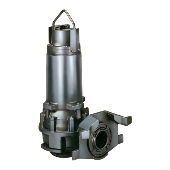
SUBMERSIBLE PUMPS
MODELS
JS6E60−E34 200/230/460/3
JS6F60−E42 200/230/460/3
JS6G60−E42 200/230/460/3
SINGLE VOLTAGE
THE GORMAN-RUPP COMPANY MANSFIELD, OHIO
GORMAN-RUPP OF CANADA LIMITED ST. THOMAS, ONTARIO, CANADA
Printed in U.S.A.
Copyright by the Gorman-Rupp Company
Advertisement
Table of Contents

Related Manuals for GORMAN-RUPP PUMPS JS6E60-E34 200/3


Summary of Contents for GORMAN-RUPP PUMPS JS6E60-E34 200/3
- Page 1 OM−03539−OM02 December 11, 1995 Rev. B 11-02-05 INSTALLATION, OPERATION, AND MAINTENANCE MANUAL WITH PARTS LIST SUBMERSIBLE PUMPS MODELS JS6E60−E34 200/230/460/3 JS6F60−E42 200/230/460/3 JS6G60−E42 200/230/460/3 SINGLE VOLTAGE THE GORMAN-RUPP COMPANY MANSFIELD, OHIO GORMAN-RUPP OF CANADA LIMITED ST. THOMAS, ONTARIO, CANADA Printed in U.S.A. Copyright by the Gorman-Rupp Company...
-
Page 2: Table Of Contents
OM−03539−02 JS6E−F−G60 230/3 SV TABLE OF CONTENTS INTRODUCTION ......PAGE I−1 SAFETY − SECTION A . - Page 3 JS6E−F−G60 230/3 SV OM−03539−02 MAINTENANCE AND REPAIR − SECTION E PAGE E−1 PUMP MODELS ........PAGE E−1 PARTS LISTS: Pump Model Assemblies...
-
Page 4: Introduction
JS SERIES OM−03539 INTRODUCTION This Installation, Operation, and Maintenance other control devices other than those integral to Manual is designed to help you achieve the best the pump motor are not covered in this manual. performance and longest life from your Gorman- Refer to other literature accompanying the pump. -
Page 5: Safety − Section A
OM−03539 JS SERIES SAFETY − SECTION A This information is specific to the Gorman-Rupp J Series Submersible pumps listed on the cover and in MAINTENANCE AND REPAIR − SECTION E. They apply throughout this manual to the in- This pump is single-voltage, either 230 structions contained in the pages which follow. - Page 6 JS SERIES OM−03539 After the pump has been installed, make The following precautions should be certain that the pump and all piping or taken before attempting to open or ser- hose connections are secure before op- vice the pump; otherwise, injury or eration.
-
Page 7: Installation − Section B
OM−03539 JS SERIES INSTALLATION − SECTION B Review all SAFETY information in Section A. d. Check that amperes, phase, voltage, and Hertz indicated on the motor name plate match the ratings on the control box. This section is intended only to summarize recom- mended installation practices for this pump. - Page 8 JS SERIES OM−03539 FIGURE B−1. PUMP DIMENSIONS PUMP MODELS JS6E60−E34 200/230/460/3 AND JS6G60−E42 200/230/460/3 PAGE B − 2 INSTALLATION...
- Page 9 OM−03539 JS SERIES FIGURE B−2. PUMP DIMENSIONS PUMP MODELS JS6F60−E42 200/230/460/3 INSTALLATION PAGE B − 3...
-
Page 10: Pump Motor Specifications
JS SERIES OM−03539 Pump Motor Specifications (104_F) ambient, plus 115_C (239_F) temperature rise. The motor furnished with this pump is a 60 Hz., Squirrel Cage, Induction Start, G-R Frame Size No. 6; Class F Insulation Rated 155_C (311_F) , 40_C See Table B−1 for motor specifications. -
Page 11: Electrical Connections
OM−03539 JS SERIES TION − SECTION C when determining the most ef- TABLE B-2. MOTOR VOLTAGE LIMITS ficient piping installation. The recommended NOMINAL PHASE MINIMUM MAXIMUM maximum submergence depth is 65 feet. VOLTAGE VOLTAGE VOLTAGE No suction piping is required in a standard sub- merged operation. -
Page 12: Control Box Connections
JS SERIES OM−03539 are shortened in the field, resulting in loss of identi- FIELD CONNECTION DIAGRAM fication markers, they can still be identified by their WYE−DELTA (REDUCED VOLTAGE START) location relative to the ground wire. START (DELTA) (WYE) Refer to Figure B−4; as seen from the free end of the cable, the conductor immediately adjacent to and clockwise from ground (green/yellow) is as- signed number T1 (T4). - Page 13 OM−03539 JS SERIES Control leads P1 and P2 provide the motor with FIELD CONNECTION DIAGRAM moisture and thermal protection. Note that thermal DIRECT START (ACROSS−THE−LINE) protection is supplementary only; separate Class 10 overload relays are required for motor running protection. The thermal protection contacts will auto- CONTROL* matically reclose when the motor cools to...
- Page 14 JS SERIES OM−03539 READ CLOCKWISE MOTOR FROM GROUND GREEN / YELLOW THERMAL 5 CONDUCTOR POWER & CONTROL CABLE THERMAL READ CLOCKWISE FROM GROUND GREEN / YELLOW THERMAL 5 CONDUCTOR POWER & CONTROL CABLE NOTE: CONDUCTOR INSULATION COLORS ARE NOT CONSISTENT MOISTURE EXCEPT FOR GREEN/YELLOW GROUND CONDUCTOR.
- Page 15 OM−03539 JS SERIES PUMP PUMP CONTROL BOX CONTROL BOX TO LEVEL CONTROL CIRCUIT TO LEVEL CONTROL CIRCUIT IN MAIN CONTROL IN MAIN CONTROL LIQUID LEVEL LIQUID LEVEL RANGE RANGE DEWATERING DEWATERING ON (FILLING) ON (FILLING) FIGURE B−6. LIQUID LEVEL DEVICES INSTALLATION PAGE B −...
-
Page 16: Operation − Section C
OM−03539 JS SERIES OPERATION − SECTION C PERFORMANCE CURVES NOTE The curves apply to standard production models. If In the performance curves which follow, perform- your pump serial number is followed by an N", ance is based on 70_F (21_C) clear water at sea your pump is not a standard production model. - Page 17 JS SERIES OM−03539 MODEL JS6F60−E42 200/230/460/3 STANDARD PERFORMANCE NOTE The curve shows 460 volt performance only. For 200 volt performance, multiply amperage shown by 2.3. For 230 volt performance, multiply amperage shown by 2. OPERATION PAGE C − 2...
- Page 18 OM−03539 JS SERIES MODEL JS6G60−E42 200/230/460/3 STANDARD PERFORMANCE NOTE The curve shows 460 volt performance only. For 200 volt performance, multiply amperage shown by 2.3. For 230 volt performance, multiply amperage shown by 2. OPERATION PAGE C − 3...
-
Page 19: Control Box And Optional Controls
JS SERIES OM−03539 Review all SAFETY information in Section A. Follow the instructions on all tags, labels and decals attached to the pump. Do not start the pump more than 10 times per hour. If the motor does not cool be- CONTROL BOX AND OPTIONAL tween starts it will overheat, resulting in CONTROLS... -
Page 20: Starting, Stopping, And Operational Checks
OM−03539 JS SERIES change the control box connections of any two Operations Checks pump motor power leads. Recheck pump twist; it To detect minor problems, check the pump for should now be in a counterclockwise direction. proper operation when it is first started and at peri- odic intervals. -
Page 21: Cold Weather Preservation
JS SERIES OM−03539 Cold Weather Preservation pump remains frozen allow additional thawing time before attempting to restart. If submerging does not thaw the pump, move it The pump will not freeze as long as the casing is into a warm area until completely thawed. submerged in liquid. -
Page 22: Troubleshooting − Section D
OM−03539 JS SERIES TROUBLESHOOTING − SECTION D Review all SAFETY information in Section A. NOTE Many of the probable remedies listed in the TROU- BLESHOOTING CHART require use of electrical test instruments; for specific procedures, see ELECTRICAL TESTING at the end of the chart. TROUBLESHOOTING CHART TROUBLE POSSIBLE CAUSE... -
Page 23: Electrical Testing
JS SERIES OM−03539 TROUBLESHOOTING CHART TROUBLE POSSIBLE CAUSE PROBABLE REMEDY (CONT.) Liquid being pumped too thick. Dilute liquid if possible. MOTOR RUNS, BUT DOES NOT Impeller worn or damaged. Replace. DELIVER RATED Insufficient liquid in wet well. Stop pump until liquid level rises. DISCHARGE. -
Page 24: Motor And Power Cable Continuity
OM−03539 JS SERIES Section B; these values apply only when the Equipment voltage at the site is the normal voltage listed. Ammeter To check AC Voltage Motor and Power Cable Continuity and current (amperage) Set the megohmmeter at R x 1 scale and zero- Ohmeter To measure resistance balance it. - Page 25 JS SERIES OM−03539 This page intentionally blank. PAGE D − 4 TROUBLESHOOTING...
-
Page 26: Maintenance And Repair − Section E . Page
OM−03539 JS SERIES MAINTENANCE AND REPAIR − SECTION E MAINTENANCE AND REPAIR OF THE WEARING PARTS OF THE PUMP WILL MAINTAIN PEAK OPERATING EFFICIENCY PUMP MODELS THE FOLLOWING PUMP MODELS, FROM SERIAL NO. 1011402 UP , ARE COVERED IN THIS SECTION. JS6E60−E34 200/230/460/3 JS6F60−E42 200/230/460/3 JS6G60−E42 200/230/460/3... -
Page 27: Section Drawing
JS SERIES OM−03539 PARTS PAGE SECTION DRAWING Figure E−1. Pump Model Assemblies PAGE E − 2 MAINTENANCE AND REPAIR... - Page 28 OM−03539 JS SERIES PUMP MODEL PARTS LIST ITEM PART NAME PART NUMBER MOTOR ASSEMBLY (200) 26825−140 MOTOR ASSEMBLY (230) 26825−052 MOTOR ASSEMBLY (460) 26825−051 : IMPELLER (JS6E) 26823−834 : IMPELLER (JS6F) 26823−836 : IMPELLER (JS6G) 26823−837 : IMPELLER KEY 26824−175 WASHER 26824−313 ALLEN SCREW...
-
Page 29: Motor Assemblies
JS SERIES OM−03539 SECTION DRAWING Figure E−2. Motor Assemblies PAGE E − 4 MAINTENANCE AND REPAIR... - Page 30 OM−03539 JS SERIES MOTOR ASSEMBLIES PARTS LIST − FIGURE E−2 ITEM PART NAME PART NUMBER ROTOR & SHAFT 26825−205 UPPER BALL BEARING 23276−009 RETAINING RING 26824−222 WASHER 26824−312 BEARING COVER 26823−683 LOWER BALL BEARING S1908 WASHER 26824−312 RETAINING RING 26824−222 BEARING HOUSING 26823−625 SCREW...
-
Page 31: Pump And Motor Disassembly
JS SERIES OM−03539 PUMP AND MOTOR DISASSEMBLY AND REASSEMBLY Review all SAFETY information in Section A. PUMP END DISASSEMBLY References are to FIGURE E−1. NOTE The pump end components may be separated from the motor without draining the oil from the motor. Do not attempt to service the pump end See MOTOR DISASSEMBLY. -
Page 32: Lower Seal Removal
OM−03539 JS SERIES hind the impeller, and tap the wedges alter- NOTE nately as required to ease the impeller off the Use caution in Step 1, tension on the seal clamp shaft. Retain the impeller key (6). springs will be released. Lower Seal Removal 1. -
Page 33: Removing Rotor And Shaft Assembly
JS SERIES OM−03539 5. To remove the moisture switch (224), remove Removing Bearings the screw (225). NOTE Because bearings can be damaged while being re- 6. Remove the upper bearing bracket (222) and moved, it is recommended that they be inspected in insulation sleeves (414). -
Page 34: Bearings
OM−03539 JS SERIES 2. Clean bearings thoroughly in fresh cleaning PUMP AND MOTOR REASSEMBLY solvent; dry with filtered compressed air. Ro- tate the bearings by hand to check for rough- MOTOR REASSEMBLY ness or binding; replace as necessary. References are to Figure E−2. 3. -
Page 35: Installing Shaft And Rotor Assembly
JS SERIES OM−03539 2. Lightly oil both ends of the rotor/shaft assem- er bearing housing (213) is fully seated against bly (201) and the I.D. and O.D. of the bearings. the stator housing shoulder. 2. Lubricate and install the O-ring (252). 3. -
Page 36: Pump End Reassembly
OM−03539 JS SERIES lets (236) are flush with the top of the cover. Se- cure the cable inlets with the screws (237). 9. Tighten the screws and nuts (239 and 240) se- The switch is extremely sensitive to atmo- curing the cables in the cable clamps (238). spheric moisture and contamination from handling;... -
Page 37: Installing Lower Seal Assembly
JS SERIES OM−03539 same O.D. as the stationary seat is a useful aid stallation. when installing these components. It is recom- mended that the pump be inverted during seal in- LOWER BEARING O-RING HOUSING STATIONARY ROTATING SEAT ELEMENT SEAL RETAINER ASSEMBLY SCREW 26824−086... - Page 38 OM−03539 JS SERIES 5. Place a clean, lint-free cloth over the stationary TEST 1: seat seal face, and install the stationary seat 1. Remove either of the two screw plugs (268) and O-ring in the seal housing cover. and O-rings (269) in the seal housing (257). 6.
-
Page 39: Installing Impeller
JS SERIES OM−03539 for more than 10 seconds. Otherwise, the Installing Volute Casing unlubricated seal will overheat and may 1. Position the volute casing against the motor burn. flange, and secure it with the screws (13). 5. Briefly apply power to the motor, and check for 2. -
Page 40: Bearings
OM−03539 JS SERIES (257) facing up; slowly open the plug to re- lease any pressure. 2. Place a clean container under the lower plug, The upper screw plug (268) in the motor remove, and roll the pump on its side to drain housing is used for testing only;... - Page 41 For U.S. and International Warranty Information, Please Visit www.grpumps.com/warranty or call: U.S.: 419−755−1280 International: +1−419−755−1352 For Canadian Warranty Information, Please Visit www.grcanada.com/warranty or call: 519−631−2870 THE GORMAN-RUPP COMPANY D MANSFIELD, OHIO GORMAN-RUPP OF CANADA LIMITED ST. THOMAS, ONTARIO, CANADA...
Need help?
Do you have a question about the JS6E60-E34 200/3 and is the answer not in the manual?
Questions and answers