Table of Contents
Advertisement
CER
OM-03690-06
October 28, 2009
INSTALLATION, OPERATION,
AND MAINTENANCE MANUAL
WITH PARTS LIST
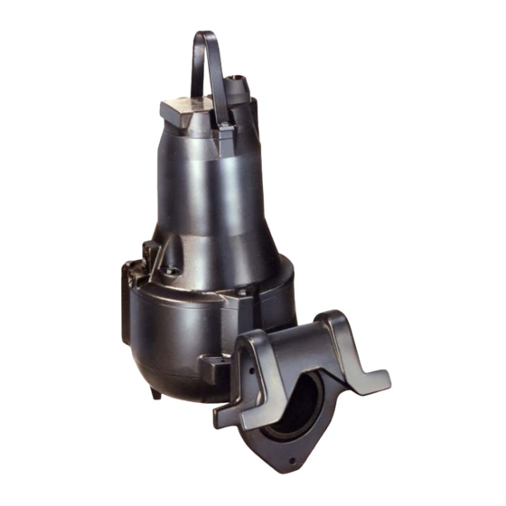
J SERIES PUMPS
MODEL
JSV3A60−E2.7 230/1
JSV3B60−E2.7 230/1
JSV3C60−E2.7 230/1
SINGLE PHASE
THE GORMAN-RUPP COMPANY D MANSFIELD, OHIO
www.grpumps.com
D
GORMAN-RUPP OF CANADA LIMITED
ST. THOMAS, ONTARIO, CANADA
Printed in U.S.A.
e
2009 The Gorman-Rupp Company
Advertisement
Table of Contents

Related Manuals for GORMAN-RUPP PUMPS J Series


Summary of Contents for GORMAN-RUPP PUMPS J Series
- Page 1 OM-03690-06 October 28, 2009 INSTALLATION, OPERATION, AND MAINTENANCE MANUAL WITH PARTS LIST J SERIES PUMPS MODEL JSV3A60−E2.7 230/1 JSV3B60−E2.7 230/1 JSV3C60−E2.7 230/1 SINGLE PHASE THE GORMAN-RUPP COMPANY D MANSFIELD, OHIO www.grpumps.com GORMAN-RUPP OF CANADA LIMITED ST. THOMAS, ONTARIO, CANADA Printed in U.S.A.
- Page 2 Register your new Gorman-Rupp pump online at www.grpumps.com Valid serial number and e-mail address required. RECORD YOUR PUMP MODEL AND SERIAL NUMBER Please record your pump model and serial number in the spaces provided below. Your Gorman-Rupp distributor needs this information when you require parts or service. Pump Model: Serial Number:...
-
Page 3: Table Of Contents
OM−03690 JSV3A−B−C60 230/1 TABLE OF CONTENTS INTRODUCTION ......PAGE I−1 SAFETY − SECTION A . - Page 4 JSV3A−B−C60 230/1 OM−03690 MAINTENANCE & REPAIR − SECTION E ..PAGE E−1 PARTS LISTS: Pump Models ........PAGE E−3 Motor Assemblies .
-
Page 5: Introduction
OM−03690 J SERIES INTRODUCTION Thank You for purchasing a Gorman-Rupp pump. The following are used to alert personnel to proce- Read this manual carefully to learn how to safely dures which require special attention, to those install and operate your pump. Failure to do so... -
Page 6: Safety − Section A
OM−03690 J SERIES SAFETY − SECTION A This information is specific to the Gorman-Rupp J Series Submersible pump listed on the cover and in MAINTENANCE AND REPAIR − SECTION E. It applies throughout this manual to the instruc- Do not connect the pump motor directly tions contained in the pages which follow. - Page 7 J SERIES OM−03690 damage to equipment and serious inju- 2. Allow the pump to cool if over- ry to personnel. heated. 3. Close the discharge valve (if used). The following precautions should be taken before attempting to open or ser- vice the pump;...
-
Page 8: Installation − Section B
OM−03690 J SERIES INSTALLATION − SECTION B Review all SAFETY information in Section A. ing, check for loose hardware at mating sur- faces. This section is intended only to summarize recom- c. The standard pump is provided with 26 ft. (8 mended installation practices for this pump. - Page 9 J SERIES OM−03690 FIGURE B−1. PUMP DIMENSIONS PAGE B − 2 INSTALLATION...
-
Page 10: Pump Motor Specifications
OM−03690 J SERIES Pump Motor Specifications (104_F) ambient, plus 115_C (239_F) temperature rise. The motor furnished with this pump is a 60 Hz., Squirrel Cage, Induction Start, G-R Frame Size No. 1; Class F Insulation Rated 155_C (311_F), 40_C See Table B−1 for motor specifications. -
Page 11: Field Wiring Connections (Incoming Power)
J SERIES OM−03690 ity, keep the line as short and straight as possible. Motor Cable Grounding Test Elbows and fittings used in a discharge line in- crease friction losses; minimize their use. It is recommended that a check valve or throttling... -
Page 12: Liquid Level Devices
OM−03690 J SERIES Refer to FIGURE B−2, and connect the pump mo- Liquid Level Devices tor cable to the control box. Optional controls available from Gorman-Rupp may provide a means to automatically regulate the liquid level. These control boxes may be con-... - Page 13 J SERIES OM−03690 PUMP PUMP CONTROL BOX CONTROL BOX TO LEVEL CONTROL CIRCUIT TO LEVEL CONTROL CIRCUIT IN MAIN CONTROL IN MAIN CONTROL LIQUID LEVEL LIQUID LEVEL RANGE RANGE DEWATERING DEWATERING ON (FILLING) ON (FILLING) FIGURE B−3. LIQUID LEVEL DEVICES INTERNAL COMPONENTS AND WIRE MARKERS MAY BE TO IEC IDENTIFICATION.
-
Page 14: Operation − Section C
OM−03690 J SERIES OPERATION − SECTION C PERFORMANCE CURVES NOTE The curves apply to standard production models. If In the performance curves which follow, perform- your pump serial number is followed by an N", ance is based on 70_F (21_C) clear water at sea your pump is not a standard production model. - Page 15 J SERIES OM−03690 PERFORMANCE CURVE − JSV3B60−E2.7 230/1 PAGE C − 2 OPERATION...
- Page 16 OM−03690 J SERIES PERFORMANCE CURVE − JSV3C60−E2.7 230/1 OPERATION PAGE C − 3...
-
Page 17: Liquid Temperature And Overheating
J SERIES OM−03690 Review all SAFETY information in Section A. is operated against a closed discharge valve for an extended period of time. Follow the instructions on all tags, labels and The submersible motor is cooled by the liquid be- decals attached to the pump. -
Page 18: Starting, Stopping, And Operational Checks . Page
OM−03690 J SERIES the pump to prevent the motor power shut off at the control box; otherwise, cable from coiling. serious personal injury could result. During motor shutoff by the thermal Suspend the pump by the lifting handle. Apply overload device, control box circuits re- power briefly and note the direction of pump twist. -
Page 19: Cold Weather Preservation
J SERIES OM−03690 repeatedly, if the control box fails to provide over- If the pump does freeze while it is out of the liquid, load or thermal protection, or if the pump is oper- submerge it until thawed; if the liquid is near freez-... -
Page 20: Troubleshooting − Section D
OM−03690 J SERIES TROUBLESHOOTING − SECTION D Review all SAFETY information in Section A. NOTE Many of the probable remedies listed in the TROU- BLESHOOTING CHART require use of electrical test instruments; for specific procedures, see ELECTRICAL TESTING at the end of the chart. -
Page 21: Electrical Testing
J SERIES OM−03690 TROUBLESHOOTING CHART TROUBLE POSSIBLE CAUSE PROBABLE REMEDY (CONT.) LIQUID BEING PUMPED TOO THICK. DILUTE LIQUID IF POSSIBLE. MOTOR RUNS, BUT DOES NOT IMPELLER WORN OR DAMAGED. REPLACE. DELIVER RATED INSUFFICIENT LIQUID IN WET WELL. STOP PUMP UNTIL LIQUID LEVEL RISES. -
Page 22: Voltage Imbalance
OM−03690 J SERIES Section B; these values apply only when the Equipment voltage at the site is the normal voltage listed. Ammeter To check AC Voltage Motor and Power Cable Continuity and current (amperage) Set the megohmmeter at R x 1 scale and zero-... -
Page 23: Maintenance & Repair − Section E
OM−03690 J SERIES MAINTENANCE AND REPAIR − SECTION E MAINTENANCE AND REPAIR OF THE WEARING PARTS OF THE PUMP WILL MAINTAIN PEAK OPERATING EFFICIENCY. PUMP MODELS THE FOLLOWING PUMP MODELS, FROM SERIAL NO. 1440422 UP , ARE COVERED IN THIS SECTION. - Page 24 J SERIES OM−03690 PARTS PAGE SECTIONAL DRAWING FIGURE E−1. PUMP MODEL ASSEMBLY PAGE E − 2 MAINTENANCE AND REPAIR...
- Page 25 OM−03690 J SERIES PUMP MODEL ASSEMBLY PARTS LIST ITEM PART NAME PART NUMBER SUBMERSIBLE SUBASSEMBLY SEE FIGURE 2 INSTALLATION KIT 48156−552 GUIDE SHOE 38236−502 1101X RUBBER SEAL 26824−784 M16 X 40 X 2 CAPSCREW 22645−877 NOT SHOWN: ROTATION DECAL 38815−023 CAUTION DECAL 38816−182...
- Page 26 J SERIES OM−03690 SECTIONAL DRAWING FIGURE E−2. SUBMERSIBLE SUBASSEMBLY PAGE E − 4 MAINTENANCE AND REPAIR...
- Page 27 OM−03690 J SERIES SUBMERSIBLE SUBASSEMBLY PARTS LIST ITEM PART NAME PART NUMBER MOTOR ASSEMBLY 26825−142 : IMPELLER (JSV3A) 26823−949 : IMPELLER (JSV3B) 38629−502 : IMPELLER (JSV3C) 38629−501 : KEY 26824−180 : IMPELLER SCREW 26824−378 VOLUTE 26827−306 HEX HD CAPSCREW 26824−352 PLUG 26824−261...
- Page 28 J SERIES OM−03690 SECTIONAL DRAWING FIGURE E−3. MOTOR ASSEMBLY PAGE E − 6 MAINTENANCE AND REPAIR...
- Page 29 OM−03690 J SERIES MOTOR ASSEMBLY PARTS LIST ITEM PART NAME PART NUMBER ROTOR AND SHAFT 26825−246 UPPER BALL BEARING 26823−725 LOWER BEARING UPPER RETAINING RING 26824−230 LOWER BALL BEARING 26823−738 LOWER BEARING SUPPORT RING 26824−326 LOWER BEARING LOWER RETAINING RING 26824−229...
-
Page 30: Pump End Disassembly
J SERIES OM−03690 PUMP AND MOTOR DISASSEMBLY AND REASSEMBLY Review all SAFETY information in Section A. assembly, be careful not to mar the surface or tapered end of the shaft. PUMP END DISASSEMBLY References are to FIGURE E−2. Do not attempt to service the pump end... -
Page 31: Removing Seal Assembly
OM−03690 J SERIES 3. If no further disassembly is required, refer to 5. Slide a pair of stiff wires with hooked ends be- INSPECTION AND CLEANING, followed by tween the seal stationary seat and the shaft PUMP END REASSEMBLY. and hook the back of the stationary seat. Pull the O-ring and stationary seat out of the bear- ing housing (213). -
Page 32: Removing Rotor And Shaft Assembly
J SERIES OM−03690 as a unit, remove the allen screws (237), and to remove the upper and lower bearings (203 pull the assembly out of the motor cover. and 207) from the shaft. 7. If desired to separate the parts removed in... -
Page 33: Cleaning Seal Assembly
OM−03690 J SERIES Cleaning Seal Assembly the inner race is useful for installing the bearing. 1. Lightly oil the upper and lower ends of the ro- tor/shaft assembly (201). Seal faces are precision-finished and sub- ject to wear patterns which cannot be re- NOTE aligned during assembly. -
Page 34: Installing Shaft And Rotor Assembly
J SERIES OM−03690 4. Slide the lower bearing housing (213) over the moved, lubricate the motor cable (234) to ease lower bearing and secure it with the retaining moving the parts during installation. ring (206). 3. Install the cable inlet and cable clamp. Discard the old rubber seal (235) and install a new one 5. -
Page 35: Pump End Reassembly
OM−03690 J SERIES 12. After checking, secure the moisture switch (224) with the screw (225). TO TEST DEVICE EXPANDER 13. Lubricate a new O-ring (247), and install it in the motor cover. Slide the motor cover over the upper bearing (203) and use a soft-faced mal- let to tap it into the stator housing. - Page 36 J SERIES OM−03690 BEARING STATIONARY HOUSING SEAT DRIVE PIN O-RING ROTATING RETAINING ELEMENT SEAL CLAMP CLAMP SPRING STATIONARY ELEMENT O-RING RETAINING SEAT FIGURE E−4. SEAL ASSEMBLY 1. Lubricate the motor shaft and the seal cavity of 6. Lightly lubricate the retaining seat, and install it the bearing housing (213).
-
Page 37: Seal Testing
OM−03690 J SERIES NOTE See SEAL TESTING before assembling the remain- ing pump end components. This test is conducted with the pump un- der power. Refer to the wiring diagram SEAL TESTING and observe all precautions outlined in INSTALLATION, Section B when con-... -
Page 38: Installing Volute Casing
J SERIES OM−03690 1. Check the impeller (5) for broken vanes, Discard the plug O-rings (269) if the plugs are re- cracks, or excessive wear. Replace as neces- moved. Lubricate the new O-rings with oil - not sary. grease - before installing them. - Page 39 For U.S. and International Warranty Information, Please Visit www.grpumps.com/warranty or call: U.S.: 419−755−1280 International: +1−419−755−1352 For Canadian Warranty Information, Please Visit www.grcanada.com/warranty or call: 519−631−2870 THE GORMAN-RUPP COMPANY D MANSFIELD, OHIO GORMAN-RUPP OF CANADA LIMITED ST. THOMAS, ONTARIO, CANADA...
Need help?
Do you have a question about the J Series and is the answer not in the manual?
Questions and answers