Table of Contents

Related Manuals for GORMAN-RUPP PUMPS S6A1-E60 460/3


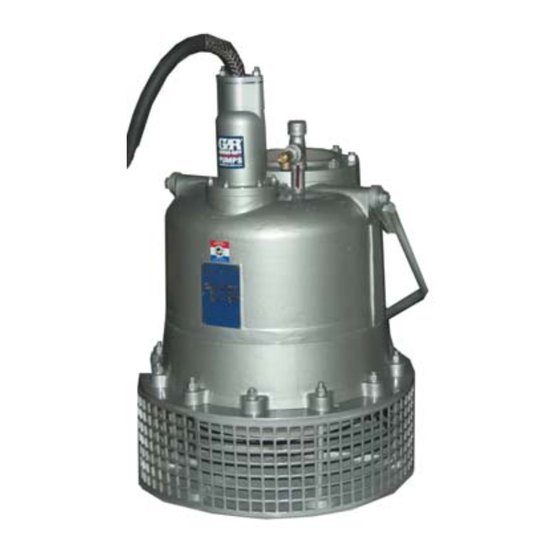
Summary of Contents for GORMAN-RUPP PUMPS S6A1-E60 460/3
- Page 1 OM‐06111‐02 March 10, 2020 INSTALLATION, OPERATION, AND MAINTENANCE MANUAL WITH PARTS LIST SUBMERSIBLE PUMPS MODELS S6A1-E60 460/3 S6A1-E60 575/3 GORMAN‐RUPP PUMPS www.grpumps.com 2020 Gorman‐Rupp Pumps Printed in U.S.A.
- Page 2 Register your new Gorman‐Rupp pump online at www.grpumps.com Valid serial number and e‐mail address required. RECORD YOUR PUMP MODEL AND SERIAL NUMBER Please record your pump model and serial number in the spaces provided below. Your Gorman‐Rupp distributor needs this information when you require parts or service. Pump Model: Serial Number:...
-
Page 3: Table Of Contents
TABLE OF CONTENTS INTRODUCTION ..........PAGE I - 1 SAFETY ‐... - Page 4 TABLE OF CONTENTS (continued) PARTS LISTS: Pump Assemblies ............PAGE E - 3 Terminal Housing and Cable Assemblies .
-
Page 5: Introduction
S SERIES PUMPS OM-06111 INTRODUCTION Thank You for purchasing a Gorman‐Rupp pump. The following are used to alert maintenance per Read this manual carefully to learn how to safely sonnel to procedures which require special atten install and operate your pump. Failure to do so tion, to those which could damage equipment, and could result in personal injury or damage to the to those which could be dangerous to personnel:... -
Page 6: Safety - Section A
OM-06111 S SERIES PUMPS SAFETY - SECTION A This information applies to the S Series submersible motor driven pumps indi cated on the front cover of this manual. Before connecting any cable to the con Because pump installations are seldom trol box, be sure to ground the control identical, this manual cannot possibly box. - Page 7 S SERIES PUMPS OM-06111 position and locked out, or that the pow trician to troubleshoot, test and/or ser er supply to the control box has been vice the electrical components of this otherwise cut off and locked out, before pump. attempting to open or service the pump assembly.
-
Page 8: Installation - Section B
OM-06111 S SERIES PUMPS INSTALLATION - SECTION B GENERAL INFORMATION ratings on the control box and incoming pow Review all SAFETY information in Section A. e. Carefully read all tags, decals, and markings Since pump installations are seldom identical, this on the pump, and perform all duties indicated. -
Page 9: Pump Motor Specifications
OM-06111 S SERIES PUMPS equipment as outlined in the National to prevent liquid from wicking through the Electric Code. Follow all safety require cable and into the motor. ments. Failure to observe these require NOTE ments could result in injury or death to Refer to the performance curve in Maintenance personnel. -
Page 10: Positioning The Pump
OM-06111 S SERIES PUMPS Positioning the Pump The pump will operate if positioned on its side, but this is not recommended because the motor NOTE torque could cause the pump to roll during opera Before installing and operating the pump, check tion. -
Page 11: Electrical Connections
OM-06111 S SERIES PUMPS ting near the pump. The discharge line must be in sible to the operator, and located close enough to dependently supported to avoid strain and vibra the pump to avoid excessive voltage drop due to tion on the pump. cable length (see Pump Power Cable Connec... -
Page 12: Grounding Methods
OM-06111 S SERIES PUMPS be of the proper size and type to ensure an ade Table B‐3. Pump Voltage Requirements quate voltage supply to the pump. Voltage avail MAXIMUM NOMINAL MINIMUM PHASE VOLTAGE able at the motor must be within the range indi VOLTAGE VOLTAGE cated in Table B‐3. -
Page 13: Pump Power Cable Connections
OM-06111 S SERIES PUMPS c. Buried electrode: If rock or stone prevents this pump is high enough to cause inju embedding the full 8 foot (2,4 m) length of the ry or death. Obtain the services of a ground rod, bury it horizontally in a trench. qualified electrician to make all electri... -
Page 14: Control Box Specifications
OM-06111 S SERIES PUMPS Connect the pump power cable to the control box NOTE as shown in the wiring diagrams in the control box For reference, internal motor wiring connections manual. Use conduit or cable clamps to secure the are shown in Maintenance and Repair - Section power cable to the control box. -
Page 15: Wiring Diagrams
OM-06111 S SERIES PUMPS PUMP PUMP CONTROL BOX CONTROL BOX TO LEVEL CONTROL CIRCUIT TO LEVEL CONTROL CIRCUIT IN MAIN CONTROL BOX IN MAIN CONTROL BOX LIQUID LEVEL LIQUID LEVEL RANGE RANGE DEWATERING DEWATERING ON (FILLING) ON (FILLING) BULB (FLOAT TYPE) DIAPHRAGM TYPE Figure B-4. -
Page 16: Operation - Section C
S SERIES PUMPS OM-06111 OPERATION - SECTION C GENERAL INFORMATION Review all SAFETY information in Section A. The pump motor and control box are not designed to be explosion‐proof. Do not operate in an explosive atmosphere. Any control box used to operate the This pump is designed to handle most pump must be approved by the Gor... -
Page 17: Impeller Rotation
OM-06111 S SERIES PUMPS or thermal protection, or if the pump is operated 4. Check the temperature before ser against a closed discharge valve for an extended vicing. period of time. 5. Vent the pump slowly and cau tiously 6. Refer to instructions in this manual before restarting the pump. -
Page 18: Starting, Stopping And Operational Checks
S SERIES PUMPS OM-06111 this pump is high enough to cause inju ry or death. Make certain that incoming power is off and locked out before inter changing motor leads. Never start the pump more than 6 times per hour. If the pump motor does not cool be tween starts, it will over‐heat, resulting in damage to the motor windings. -
Page 19: Cold Weather Preservation
OM-06111 S SERIES PUMPS COLD WEATHER PRESERVATION To avoid serious damage to the pump, check for unusual noises or excessive vi Do not attempt to thaw the pump by us bration while the pump is running. If noise ing a torch or other source of flame. This or vibration is excessive, stop operation could damage gaskets, O‐rings or heat and refer to the troubleshooting chart in the... -
Page 20: Draining Oil
S SERIES PUMPS OM-06111 month thereafter. Check the motor lubrication level Adding Oil any time the pressure relief valve is activated, and replace the oil annually. Refer to Table B-2 in INSTALLATION for oil ca pacities and positions for filling the seal cavity in Before installing or removing the lubrication your pump. -
Page 21: Troubleshooting - Section D
OM-06111 S SERIES PUMPS TROUBLESHOOTING - SECTION D Review all SAFETY information in Section A. NOTE Many of the probable remedies listed in the TROU BLESHOOTING CHART require use of electrical test instruments; for specific procedures, see ELECTRICAL TESTING at the end of the chart. TROUBLESHOOTING CHART TROUBLE POSSIBLE CAUSE... - Page 22 S SERIES PUMPS OM-06111 TROUBLESHOOTING CHART (cont'd) TROUBLE POSSIBLE CAUSE PROBABLE REMEDY Discharge head too high. Reduce discharge head or install MOTOR RUNS, BUT PUMP FAILS staging adaptor and additional TO DELIVER pump. RATED DIS Low or incorrect voltage. Measure control box voltage, both CHARGE.
- Page 23 OM-06111 S SERIES PUMPS ELECTRICAL TESTING 3. The pump submerged and running under full load. Make the electrical checks which follow to deter The voltage measured under each condition mine if pump malfunctions are being caused by must be the same. problems in the motor or in the motor cable.
- Page 24 S SERIES PUMPS OM-06111 the other test lead to each of the motor cable should be rechecked regularly. If resistance leads in turn. Note the readings. reads less than 1 megohm, insulation should be checked more closely and frequently. b. Readings will indicate resistance values in both the power cable and motor windings.If resistance reads infinity (1), insulation is c.
-
Page 25: Pump Maintenance And Repair - Section E
MAINTENANCE AND REPAIR OF THE WEARING PARTS OF THE PUMP WILL MAINTAIN PEAK OPERATING PERFORMANCE. STANDARD PERFORMANCE FOR PUMP MODELS S6A1-E60 460/3 AND S6A1-E60 575/3 Based on 70_F (21_C) clear water at sea level Contact the Gorman‐Rupp Company to verify per... - Page 26 S SERIES PUMPS OM-06111 ILLUSTRATION PARTS PAGE 35 36 Figure E-1. S6A1-E60 460/3 And S6A1-E60 575/3 Pump Assemblies PAGE E - 2 MAINTENANCE AND REPAIR...
- Page 27 OM-06111 S SERIES PUMPS S6A1-E60 460/3 And S6A1-E60 575/3 Pump Assemblies Parts List (From S/N 1723924 Up) If your pump serial number is followed by an “N”, your pump is NOT a standard production model. Contact the Gorman‐Rupp Company to verify part numbers.
- Page 28 S SERIES PUMPS OM-06111 ILLUSTRATION Ñ Ñ Ñ Ñ Ñ Ç Ç Ç Ç Ç Ñ Ñ Ñ Ç Ç Ç Ç Ñ Ñ Ç Ç Ç Ç Ç Ñ Ñ Ñ Ç Ç Ç Ç Ñ Ñ Ñ Ñ Ì...
- Page 29 OM-06111 S SERIES PUMPS Terminal Housing And Cable Assembly Parts List ITEM PART PART NAME NUMBER TERMINAL GLAND -460V 10660 13040 -575V 38381-614 13040 CABLE -460V 10325 -575V 47323-045 CABLE GRIP -460V 11227E -575V 11227K STUD C0808 17000 HEX NUT D08 17000 DRIVE SCREW BM#04-03 17000...
- Page 30 S SERIES PUMPS OM-06111 used, disconnect the piping before attempting to PUMP AND SEAL DISASSEMBLY AND move the pump. REASSEMBLY Review all SAFETY information in Section A. Do not attempt to lift the pump by the motor power cable or the piping. Attach proper lifting equipment to the lifting Do not attempt to service the pump as...
- Page 31 OM-06111 S SERIES PUMPS disturbed. Repair gaskets and O‐rings are listed in move the plug slowly and permit pressure the Parts List. to vent to atmosphere. Lay the pump on its side with the pipe plugs (28) facing up. Clean any dirt from around the plugs. Remove the pipe plug, and install a short 3/8‐inch NPT nipple in the hole.
- Page 32 S SERIES PUMPS OM-06111 Impeller Removal Upper Seal Removal (Figures E-1 and E-3) (Figure E-1) Unless cracked or otherwise worn, it is not neces sary to remove the intermediate (27) for access to Wedge a block of wood between the vanes of the the upper seal assembly (22).
- Page 33 OM-06111 S SERIES PUMPS wrap a small rag around the shaft to prevent for fine file or hand honing stone to restore original eign material from entering the motor cavity. contours. If the shaft is bent or severely damaged, the rotor and shaft must be replaced as an assem Carefully inspect any O‐rings or gaskets before re...
- Page 34 S SERIES PUMPS OM-06111 ROTOR STATIONARY SHAFT SEAL SEAT ROTATING ELEMENT STATIONARY ELEMENT SPRING BELLOWS AND RETAINING ASSY SPRING RETAINER SEAL RETAINING RING STATIONARY O‐RING SEAL SEAT STATIONARY O‐RING ELEMENT DIFFUSER ROTATING ELEMENT BELLOWS AND RETAINING ASSY SPRING IMPELLER WASHER IMPELLER SHIM SET Figure E-3.
- Page 35 OM-06111 S SERIES PUMPS may not stay in the bellows retainer when turned shaft, use hand pressure only. A push tube cut from upside down, place a small amount of grease at a length of plastic pipe will aid in installing seal equal spaces on the back of the element and posi...
- Page 36 S SERIES PUMPS OM-06111 impeller onto the shaft until seated firmly against pump end disassembly, allowance must be made the upper impeller washer and shim set. for bearing play when checking impeller clearance. Final impeller clearance must be determined with After the impeller is installed, coat the threads of the pump in a normal upright operating position.
- Page 37 OM-06111 S SERIES PUMPS Centers. Separate the terminal housing and power cable assembly (14) from the motor housing. No further disassembly is required to test the stator or power cable. To disconnect the power cable (14), remove the The electrical power used to operate nuts (16) securing the terminal gland (12) to the ter...
- Page 38 S SERIES PUMPS OM-06111 damage is extensive and the terminal plate and ter Rotor And Bearing Removal minals are to be replaced, simply cut the power (Figure E-1) cable leads above the terminal collars and heat‐ shrink tubing, and discard the terminal plate and Set the intermediate and rotor assembly on a clean terminals.
- Page 39 OM-06111 S SERIES PUMPS rotor shaft. Remove the bearing cap (32) and gas ing tolerances and materials are closely ket (33) from the rotor shaft. controlled by the manufacturer, and any deviation can cause damage or operating NOTE problems. Replace the stator, or return it to It may be necessary to use the bearing cap (32) and one of The Gorman‐Rupp Authorized Sub...
- Page 40 S SERIES PUMPS OM-06111 Test the new stator as indicated in Electrical Test mersible Repair Centers or The Gorman‐ ing in TROUBLESHOOTING, Section D, to ensure Rupp factory, if defective. that no damage has occurred during transit or han NOTE dling.
- Page 41 OM-06111 S SERIES PUMPS Bearing Installation ing onto the shaft until it is fully seated against the shaft shoulder. This should be done quickly, in one (Figure E-1) continuous motion, to prevent the bearing from cooling and sticking on the shaft. Inspect the rotor shaft (31) for damaged threads, scoring in the seal area, and a nicked or damaged keyway.
- Page 42 S SERIES PUMPS OM-06111 INSTALLATION OF SKF 5200 AND 5300 SERIES BEARINGS PART NUMBER MARKINGS ARE LOCATED EITHER ON BEARING O.D. (OFFSET FROM CENTER) OR ON SIDE FACE OF BEARING. FOR EITHER TYPE, POSITION BEAR ING WITH TEXT AWAY FROM IM DIRECTION OF PELLER.
- Page 43 OM-06111 S SERIES PUMPS Refer to PUMP END REASSEMBLY, and reas beyond the terminal housing. Temporarily tape the semble the pump end components. green and yellow ground wires to the cable. Sealing Terminal Housing Connections Terminal Housing And Power Cable With Silicone Adhesive Reassembly And Installation (Figure E-2)
- Page 44 S SERIES PUMPS OM-06111 NOTE NOTE Clean the cable leads and terminal plate in the ar Do not use a mold or reservoir with the silicone eas to be sealed with cleaning solvent. Incomplete adhesive. sealing will occur if the surfaces are dirt, oil or grease coated.
- Page 45 OM-06111 S SERIES PUMPS 1 YELLOW - CONNECT TERMINAL TO GROUND INSIDE TERMINAL HOUSING WHITE (T1) 2 GREEN - TOGETHER IN ONE TERMINAL. CONNECT TERMINAL TO GROUND INSIDE TERMINAL HOUSING (T3) BLACK (T2) Figure E-6. Terminal Housing Wiring Connections Sealing Terminal Housing Connections terminal collars and onto the terminal plate.
- Page 46 S SERIES PUMPS OM-06111 When potting has been completed, leave the ter NOTE minal plate assembly undisturbed until the potting A .09 to .15 in. (3,05 mm) gap is required between material has cured. Complete curing usually takes the terminal gland flange and the terminal housing about 24 hours.
- Page 47 OM-06111 S SERIES PUMPS both the motor and seal cavities. Test the motor the stationary seal seat between the seal and mo tor cavities. cavity for its full duration first, then use the shutoff valve to maintain the motor cavity vacuum while testing the seal cavity.
- Page 48 S SERIES PUMPS OM-06111 stored in a clean, tightly closed container in a rea sonably dry environment. Table E-2. Oil Quantity Pump Model Seal Cavity Motor Cavity 176 ounces (5,2 liters) 832 ounces (24,6 liters) Table E‐3. Pump Oil Specifications Specifications: Type .
- Page 49 For Warranty Information, Please Visit www.grpumps.com/warranty or call: U.S.: 419-755-1280 Canada: 519-631-2870 International: +1-419-755-1352 GORMAN‐RUPP PUMPS...
Need help?
Do you have a question about the S6A1-E60 460/3 and is the answer not in the manual?
Questions and answers