Table of Contents
Advertisement
Quick Links
CER
INSTALLATION, OPERATION,
AND MAINTENANCE MANUAL
JSV4F60−E8.7 230/3
JSV4G60−E11 230/3
THE GORMAN-RUPP COMPANY MANSFIELD, OHIO
GORMAN-RUPP OF CANADA LIMITED ST. THOMAS, ONTARIO, CANADA
WITH PARTS LIST
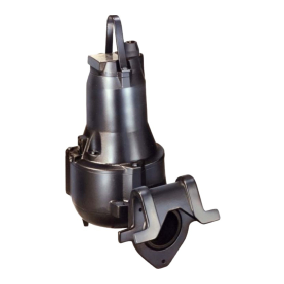
SUBMERSIBLE PUMPS
MODELS
DUAL VOLTAGE
Copyright by the Gorman-Rupp Company
OM−03592−OM01
NOVEMBER 30, 1990
JSV4F60−E8.7 460/3
JSV4G60−E11 460/3
Printed in U.S.A.
Rev. B
Advertisement
Table of Contents

Related Manuals for GORMAN-RUPP PUMPS JSV4F60-E8.7 230/3


Summary of Contents for GORMAN-RUPP PUMPS JSV4F60-E8.7 230/3
- Page 1 OM−03592−OM01 NOVEMBER 30, 1990 Rev. B INSTALLATION, OPERATION, AND MAINTENANCE MANUAL WITH PARTS LIST SUBMERSIBLE PUMPS MODELS JSV4F60−E8.7 230/3 JSV4F60−E8.7 460/3 JSV4G60−E11 230/3 JSV4G60−E11 460/3 DUAL VOLTAGE THE GORMAN-RUPP COMPANY MANSFIELD, OHIO GORMAN-RUPP OF CANADA LIMITED ST. THOMAS, ONTARIO, CANADA Printed in U.S.A.
-
Page 2: Table Of Contents
OM−03592−OM01 JSV4F−G60 DV TABLE OF CONTENTS INTRODUCTION ......PAGE I−1 SAFETY − SECTION A . - Page 3 JSV4F−G60 DV OM−03592−OM01 MAINTENANCE & REPAIR − SECTION E ..PAGE E−1 PARTS LIST − FIGURE E−1 ......PAGE E−3 OPTIONS .
- Page 4 JSV4F−G60 DV OM−03592−OM01 INTRODUCTION This Installation, Operation, and Maintenance and thermal switches. Control boxes and other Manual is designed to help you achieve the best control devices other than those integral to the performance and longest life from your Gorman− pump motor are not covered in this manual.
- Page 5 JSV4F−G60 DV OM−03592−OM01 This page intentionally blank. PAGE I−2 INTRODUCTION...
-
Page 6: Safety − Section A
OM−03592−OM01 JSV4F−G60 DV SAFETY − SECTION A These warnings are specific to the Gorman−Rupp Í Í Í Í Í Í WARNING J Series Submersible pumps listed on the cover Í Í Í Í Í Í and in MAINTENANCE AND REPAIR − SECTION Í... - Page 7 JSV4F−G60 DV OM−03592−OM01 Í Í Í Í Í Í ALLOW THE PUMP TO COOL IF OVER- Í Í Í Í Í Í WARNING HEATED. Í Í Í Í Í Í CLOSE THE DISCHARGE VALVE (IF THE FOLLOWING PRECAUTIONS SHOULD BE USED).
-
Page 8: Installation − Section B
OM−03592−OM01 JSV4F−G60 DV INSTALLATION − SECTION B Review all SAFETY information in Section A. b. Check for loose attaching hardware. Since This section is intended only to summarize recom- gaskets tend to shrink after drying, check mended installation practices for these pumps. If for loose hardware at mating surfaces. - Page 9 JSV4F−G60 DV OM−03592−OM01 FIGURE B−1. PUMP DIMENSIONS PAGE B−2 INSTALLATION...
-
Page 10: Pump Motor Specifications
OM−03592−OM01 JSV4F−G60 DV Pump Motor Specifications (311_F), 40_C (104_F) ambient, plus 115_C (239_F) temperature rise. The motor furnished with this pump is a 60 Hz., Squirrel Cage, Induction Start, G−R Frame Size See Table B−1 for motor specifications for each No. -
Page 11: Electrical Connections
JSV4F−G60 DV OM−03592−OM01 able at the motor must be within the range indi- The optional discharge elbow/baseplate is drilled cated in Table B-2. for a 3−inch or 4−inch discharge flange connec- tion. Either hose or rigid pipe may be used to make discharge connections. -
Page 12: Motor Cable Grounding Test
OM−03592−OM01 JSV4F−G60 DV Motor Cable Grounding Test THE CONTROLS INSTALLED HAVE BEEN AP- PROVED BY GORMAN−RUPP . Í Í Í Í Í Í This pump is shipped completely wired for the volt- WARNING Í Í Í Í Í Í age shown on the nameplate, and is ready for op- Í... -
Page 13: Wiring Diagrams
JSV4F−G60 DV OM−03592−OM01 Wiring Diagrams Complete schematic wiring diagrams for the motor are shown In FIGURE B−4. The motor wiring diagram is shown in FIGURE B−3. MOTOR Liquid Level Devices LOW VOLTAGE HIGH VOLTAGE É É É É É É CAUTION É... - Page 14 OM−03592−OM01 JSV4F−G60 DV FIGURE B−4. INTERNAL MOTOR WIRING INSTALLATION PAGE B−7...
-
Page 15: Operation − Section C
OM−03592−OM01 JSV4F−G60 DV OPERATION − SECTION C PERFORMANCE CURVES NOTE In the performance curves which follow, perform- These curves appy to standard production models. ance is based on 70_F clear water at sea level. The If your pump serial number is followed by an "N", performance of your pump may be different due to your pump is not a standard production model. - Page 16 JSV4F−G60 DV OM−03592−OM01 PERFORMANCE CURVE − JSV4G60−E11 NOTE The curve shows 460 volt performance only. For 230 volt performance, multiply amperage shown by 2. PAGE C−2 OPERATION...
-
Page 17: Control Box And Optional Controls
OM−03592−OM01 JSV4F−G60 DV Review all SAFETY information in Section A. Impeller Rotation Follow the instructions on all tags, labels and decals attached to the pump. CONTROL BOX AND OPTIONAL CONTROLS See the operating instructions furnished with the control box, and with other optional accessories and controls, before attempting to start the pump. -
Page 18: Starting, Stopping, And Operational Checks
JSV4F−G60 DV OM−03592−OM01 STARTING, STOPPING, AND OPERATIONAL After stopping the pump, be sure to perform all re- CHECKS quired maintenance and preservation procedures. Cold Weather Preservation Starting É É É É É É The pump will not freeze as long as the casing is É... - Page 19 OM−03592−OM01 JSV4F−G60 DV momentarily may backflush this blockage. If back- SURE INTO THE PUMP CASING TO REMOVE A flushing does not clear the debris, remove the BLOCKAGE. THIS COULD RESULT IN PER- pump from the wet well and clear manually. SONAL INJURY OR DAMAGE TO THE EQUIP- Í...
- Page 20 JSV4F−G60 DV OM−03592−OM01 This page intentionally blank. PAGE C−6 OPERATION...
-
Page 21: Troubleshooting − Section D
OM−03592−OM01 JSV4F−G60 DV TROUBLESHOOTING − SECTION D Review all WARNINGS in Section A. NOTE Many of the probable remedies listed in the TROUBLESHOOTING CHART require use of electrical test instru- ments; for specific procedures, see ELECTRICAL TESTING at the end of the chart. TROUBLESHOOTING CHART TROUBLE POSSIBLE CAUSE... - Page 22 JSV4F−G60 DV OM−03592−OM01 TROUBLESHOOTING CHART TROUBLE POSSIBLE CAUSE PROBABLE REMEDY IMPELLER OR DISCHARGE LINE CLEAR CLOGGED. (C0NT.) LIQUID BEING PUMPED TOO THICK. DILUTE LIQUID IF POSSIBLE. MOTOR RUNS BUT DOES IMPELLER WORN OR DAMAGED. REPLACE. NOT DELIVER RATED DIS- INSUFFICIENT LIQUID IN WET WELL. STOP PUMP UNTIL LIQUID LEVEL RISES. CHARGE IMPELLER ROTATING IN WRONG DI−...
-
Page 23: Electrical Testing
OM−03592−OM01 JSV4F−G60 DV ELECTRICAL TESTING tests which follow. use the commercial equipment listed below, or equivalent substitutes. Make the electrical checks which follow to deter- É É É É É É mine if pump malfunctions are being caused by CAUTION É... -
Page 24: Insulation Resistance
JSV4F−G60 DV OM−03592−OM01 green/yellow ground lead. Touch the other test b. Repeat Step a. with each set of leads. The three lead to each of the motor cable leads in turn. Note readings shall be as close as can be measured. the readings. -
Page 25: Maintenance & Repair − Section E
OM−03592−OM01 JSV4F−G60 DV MAINTENANCE & REPAIR − SECTION E MAINTENANCE AND REPAIR OF THE WEARING PARTS OF THE PUMP WILL MAINTAIN PEAK OPER- ATING EFFICIENCY PUMP MODELS THE FOLLOWING PUMP MODELS, FROM SERIAL NO. 932241 UP , ARE COVERED IN THIS SECTION JSV4F60−E8.7 230/3 JSV4F60−E8.7 460/3 JSV4G60−E11 230/3... - Page 26 JSV4F−G60 DV OM−03592−OM01 SECTIONAL DRAWING FIGURE E−1. PUMP MODEL ASSEMBLY 46127−953 PAGE E−2 MAINTENANCE AND REPAIR...
-
Page 27: Parts List Figure E−1
OM−03592−OM01 JSV4F−G60 DV PARTS PAGE PARTS LIST FIGURE E−1 ITEM PART NAME PART NUMBER MOTOR ASSEMBLY (230V) 26824−878 MOTOR ASSEMBLY (460V) 26823−877 : IMPELLER (JSV4F60) 26823−875 : IMPELLER (JSV4G60) 26823−874 : SHAFT KEY 26824−173 SCREW 26824−379 VOLUTE CASING 26823−710 SCREW 26824−354 : RUBBER SEAL 26824−067... - Page 28 JSV4F−G60 DV OM−03592−OM01 SECTIONAL DRAWING FIGURE E−2. MOTOR ASSEMBLY 47111−906 PAGE E−4 MAINTENANCE AND REPAIR...
-
Page 29: Parts List − Figure E−2
OM−03592−OM01 JSV4F−G60 DV PARTS LIST − FIGURE E−2 ITEM PART NAME PART NUMBER ROTOR AND SHAFT 26823−217 UPPER BALL BEARING 26823−731 LOWER BEARING UPPER RETAINING RING 26823−227 LOWER BALL BEARING 26823−737 LOWER BEARING LOWER SUPPORT RING 26824−319 LOWER BEARING UPPER RETAINING RING 26824−228 LOWER BEARING HOUSING 26823−630... -
Page 30: Pump End Disassembly
JSV4F−G60 DV OM−03592−OM01 PUMP AND MOTOR DISASSEMBLY AND REASSEMBLY É É É É É É Review all WARNINGS in Section A. CAUTION É É É É É É É É É É É É IF NECESSARY TO PRY COMPONENTS APART Í... -
Page 31: Motor Disassembly
OM−03592−OM01 JSV4F−G60 DV An alternative method of removing the impel- To remove the motor cable (234), cable inlet ler is to place two wedges opposite each other be- (236), cable clamp (238), and rubber seal (235) as hind the impeller. Tap the wedges alternately as a complete unit, remove the four screws (237) se- required to ease the impeller squarely off the shaft. - Page 32 JSV4F−G60 DV OM−03592−OM01 O-RING ROTATING STATIONARY ELEMENT SEAT DRIVE O-RING O-RING SEAL CLAMP STATIONARY SPRING ELEMENT SEAL O-RING HOUSING FIGURE E−3. 26824−094 SEAL ASSEMBLY See LUBRICATION, and drain the oil from the (213). Hook the back end of the stationary seat, seal housing (257).
-
Page 33: Inspection And Cleaning
OM−03592−OM01 JSV4F−G60 DV To remove the upper bearing (203), lightly oil Other Reusable Parts (Except Seal Assembly) the upper end of the rotor/shaft (201) and pull or Thoroughly clean all reusable parts. press the bearing off the shaft. Inspect all mating surfaces and the rotor/ To remove the lower bearing (207), remove shaft assembly for nicks or burrs, and restore to the lower retaining ring (209) and support ring... - Page 34 JSV4F−G60 DV OM−03592−OM01 for obvious damage. (If required, see ELECTRI- screws (239). CAL TESTING in TROUBLESHOOTING − SEC- TION D.) 10. It is recommended that the moisture switch (224) be checked before installation. See FIGURE E−4, and install the switch in a simple bell circuit or É...
-
Page 35: Installing Bearings
OM−03592−OM01 JSV4F−G60 DV the junction box cover (452). Secure the cover to Press the lower bearing (207) on the shaft un- the motor housing (302) with four screws (250). til it seats squarely against the shaft shoulder. 15. Secure the lifting handle (231) to the motor Install the lower support ring (208), and se- housing (302) with two screws (233). -
Page 36: Seal Testing
JSV4F−G60 DV OM−03592−OM01 Use hand pressure only to install seal components. Seal Testing A push tube cut from plastic pipe approximately the The seal assemblies should be tested under pres- same O.D. as the stationary seat is a useful aid sure and partially submerged in water before the when installing these components. -
Page 37: Pump End Reassembly
OM−03592−OM01 JSV4F−G60 DV − SECTION B WHEN CONNECTING THE MO- All part number references are to FIGURE E−1. TOR CABLE TO THE CONTROL BOX. OTHER- WISE, THE PUMP COULD BE DAMAGED, AND Check the impeller (5) for broken vanes, PERSONNEL EXPOSED TO INJURY OR cracks, or excessive wear. -
Page 38: Draining Oil
JSV4F−G60 DV OM−03592−OM01 NOTES If the oil is clear, it can be reused. There are two screw plugs (268) in the seal housing (257), and another at the top of the motor housing If the oil is milky or contains a small amount of (302). - Page 39 For U.S. and International Warranty Information, Please Visit www.grpumps.com/warranty or call: U.S.: 419−755−1280 International: +1−419−755−1352 For Canadian Warranty Information, Please Visit www.grcanada.com/warranty or call: 519−631−2870 THE GORMAN-RUPP COMPANY D MANSFIELD, OHIO GORMAN-RUPP OF CANADA LIMITED ST. THOMAS, ONTARIO, CANADA...
Need help?
Do you have a question about the JSV4F60-E8.7 230/3 and is the answer not in the manual?
Questions and answers