
Subscribe to Our Youtube Channel
Related Manuals for Sun Microsystems StorEdge 6320


Summary of Contents for Sun Microsystems StorEdge 6320
- Page 1 Sun StorEdge 6320 System 1.2 ™ Installation Guide Sun Microsystems, Inc. www.sun.com Part No. 816-7878-13 April 2004, Revision 1 Submit comments about this document at: http://www.sun.com/hwdocs/feedback...
- Page 2 Parts of the product may be derived from Berkeley BSD systems, licensed from the University of California. UNIX is a registered trademark in the U.S. and in other countries, exclusively licensed through X/Open Company, Ltd. Sun, Sun Microsystems, the Sun logo, Java, and Sun StorEdge are trademarks or registered trademarks of Sun Microsystems, Inc. in the U.S. and other countries.
-
Page 3: Table Of Contents
Contents Preface i-xi Understanding the Sun StorEdge 6320 System 1-1 Hardware Overview 1-2 1.1.1 System Cabinet 1-2 1.1.2 Service Panel 1-4 1.1.3 Storage Service Processor 1-4 1.1.4 Storage Arrays 1-4 1.1.5 Understanding RAID Levels 1-5 Software Overview 1-6 1.2.1 Sun StorEDGE 6320 System Management Software 1-7 1.2.2... - Page 4 Establishing the Initial Configuration 4-1 Logging In to the Configuration Service Web Interface 4-6 Setting the Default Configuration 5-1 Logging Into the System 5-2 Adding Administration Information 5-3 5.2.1 Providing a System Description 5-3 Sun StorEdge 6320 System 1.2 Installation Guide • November 2003...
- Page 5 5.2.2 Changing the Time Zone 5-4 5.2.3 Changing the System Time 5-5 Creating Volumes 5-6 Initializing the Sun StorEdge Remote Response Service 6-1 Remote Response Service Initialization 6-2 Shared Remote Response Telephone Line 6-4 A. Connecting a Second System Cabinet A-1 Connecting an Expansion Cabinet to a Base Cabinet with Internal Switches A-2 A.1.1 Connecting the Fibre Channel Cables A-2...
- Page 6 Creating Initiator Groups E-24 E.4.3 Creating Initiators E-28 E.4.4 Creating Volumes E-29 E.4.5 Creating Volume Groups E-36 F. Installing the USB Flash Disk D-1 4.Restoring Configuration Files D-2 Index I-i Sun StorEdge 6320 System 1.2 Installation Guide • November 2003...
- Page 7 TABLE 2-5 Configuration 2–17 Serial Connection—FRU List 3–5 TABLE 3-1 Port Numbers 4–6 TABLE 4-1 Default Sun StorEdge 6320 System Configuration 5–1 TABLE 5-1 Supported Host Operating Systems D–1 TABLE D-2 CLI Client Software D–2 TABLE D-3 Configuration Field Descriptions E–17 TABLE 6-1 Fibre Channel Configuration Fields E–21...
- Page 9 Figures Stabilizer Legs 2–7 FIGURE 2-1 Installing the Right Stabilizer Leg 2–7 FIGURE 2-2 Adjusting the Leveling Pads on the Stabilizer Leg 2–8 FIGURE 2-3 Leveling Pads 2–9 FIGURE 2-4 Removing the Bottom Right Front Mounting Screws 2–10 FIGURE 2-5 Attaching the Floor-mounting Brackets 2–10 FIGURE 2-6 Location of Key Switch on Bottom Front Panel 2–14...
- Page 10 Storage Log In 5–7 FIGURE 5-5 Manage Volumes - Create 5–8 FIGURE E-1 Enter Name and Select Pool 5–9 FIGURE E-2 Enter Size and Permissions 5–10 FIGURE E-3 Add Volume to Group 5–11 FIGURE E-4 Confirm Choices 5–12 FIGURE E-5 Mail Notification 5–12 FIGURE E-6 Outstanding Jobs 5–13...
- Page 11 Manage Volumes - Create E–30 FIGURE E-22 Enter Name and Select Pool E–31 FIGURE E-23 Enter Size and Permissions E–32 FIGURE E-24 Add Volume to Group E–33 FIGURE E-25 Confirm Choices E–34 FIGURE E-26 Mail Notification E–34 FIGURE E-27 Outstanding Jobs E–35 FIGURE E-28 Manage Volume Groups - Create E–36 FIGURE E-29...
- Page 13 Chapter 5 steps you through the initial configuration parameters using the web- based Configuration Services. Chapter 6 explains how to initialize the Sun StorEdge Remote Response service. Appendix A explains how to add a second cabinet to the Sun StorEdge 6320 systems.
- Page 14 Refer to one or more of the following for this information: Solaris Handbook for Sun Peripherals AnswerBook2™ online documentation for the Solaris™ software environment Other software documentation that you received with your system xii Sun StorEdge 6320 System 1.2 Installation Guide • November 2003...
-
Page 15: Typographic Conventions
Typographic Conventions Typeface Meaning Examples The names of commands, files, Edit your .login file. AaBbCc123 and directories; on-screen Use ls -a to list all files. computer output % You have mail. What you type, when AaBbCc123 contrasted with on-screen Password: computer output AaBbCc123 Book titles, new words or... - Page 16 Sun StorEdge 6320 System Documentation The following is a list of documents related to the Sun StorEdge 6320 system. For any document number with nn as a suffix, use the most current document. Subject Title Part Number Late-breaking news • Sun StorEdge 6320 System 1.0 Release Notes...
-
Page 17: Related Documentation
Related Documentation The following documents provide detailed information about related products. Product Title Part Number San Foundation Software • Sun StorEdge SAN Foundation 4.2 Configuration Guide 817-1245-nn Traffic Manager Software • Sun StorEdge Traffic Manager Software Installation and 816-1420-nn Configuration Guide •... -
Page 18: Accessing Sun Documentation Online
You can submit your comments by going to: http://www.sun.com/hwdocs/feedback Please include the title and part number of this document with your feedback: Sun StorEdge 6320 System 1.2 Installation Guide part number 816-7878-nn. xvi Sun StorEdge 6320 System 1.2 Installation Guide • November 2003... -
Page 19: Understanding The Sun Storedge 6320 System
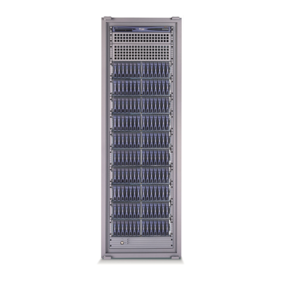
C H A P T E R Understanding the Sun StorEdge 6320 System The Sun StorEdge 6320 system offers a complete storage solution with a modular architecture and integrated system-wide manageability. The Sun StorEdge 6320 system scales incrementally from 500 gigabytes (GB) to 45 terabytes (TB) of storage while balancing capacity and performance. -
Page 20: Hardware Overview
From the front of the system cabinet, you can view the LEDs for the Storage Service Processor and the system arrays. Whenever any LEDs are yellow or red, check the logs and reports in the diagnostic software, Storage Automated Diagnostic Environment Software. Sun StorEdge 6320 System 1.2 Installation Guide • November 2003... -
Page 21: Service Panel
From the back of the system cabinet, you can access the Service Processor Panel for cabling the storage area network (SAN) and local area network (LAN) to the Sun StorEdge 6320 system. You can also access the array field replaceable units (FRUs) such as power and cooling units and the array controllers. -
Page 22: Storage Service Processor
1.1.4 Storage Arrays The Sun StorEdge 6320 system uses arrays as storage modules. An array has a master and an alternate master controller with expansion units. Each tray of the array is 3RU and 18-inches deep and holds from seven to fourteen 1-inch drives. - Page 23 Since the parity information is spread across multiple disks, only a percentage of the disks is used for parity information, which improves the efficiency of available storage space. Chapter 1 Understanding the Sun StorEdge 6320 System...
-
Page 24: Software Overview
Software Overview This section describes the following software used in the Sun StorEdge 6320 System : System Management software Data host software External management host software Other supported software Note – Supported software is available for download from: http://wwws.sun.com/software/download/ Also, the Sun StorEdge 6000 Family Host Installation Software CD contains the... -
Page 25: Management Software
The installed version of the Storage Automated Diagnostic Environment Environment Software Software is a diagnostic monitoring tool for the Sun StorEdge 6320 system. - for Sun StorEdge 6320 It can be configured to monitor on a 24-hour basis, collecting information system diagnostics that enhances the reliability, availability, and serviceability of the system. -
Page 26: Data Host Software
HP-UX Sun StorEdge Traffic Manager for HP-UX Storage Automated Diagnostic Environment Software - Client Edition Red Hat Linux 7.2 (Single-path support only) Storage Automated Diagnostic Environment Software - Client Edition Sun StorEdge 6320 System 1.2 Installation Guide • November 2003... -
Page 27: External Management Host Software
Windows Storage Automated Diagnostic Storage Automated Diagnostic Environment software client edition resides Environment Software - Device SAN devices assist for measuring the online health and diagnostic Edition monitoring tool of the SAN. Chapter 1 Understanding the Sun StorEdge 6320 System... -
Page 28: Other Supported Software
1.2.4 Other Supported Software lists other software supported by the Sun StorEdge 6320 system. Refer to TABLE 1-5 the software documentation for installation instructions. Other Supported Software for the Sun StorEdge 6320 System TABLE 1-5 Software Description •Sun StorEdge Enterprise Storage Manager Other Supported Software •Sun StorEdge Availability Suite... - Page 29 Create an initiator group. - Create an initiator to add to the group. - Create a volume and add it to the volume group. - Select Reports to verify the volume and initiator. Chapter 1 Understanding the Sun StorEdge 6320 System 1-11...
- Page 30 1-12 Sun StorEdge 6320 System 1.2 Installation Guide • November 2003...
- Page 31 Installing the Hardware This chapter provides the information that you will need to set up your Sun StorEdge 6320 system hardware and cabling. Additionally, this chapter cites areas that you will want to consider before actually setting up the system and then beginning the initial configuration.
-
Page 32: Planning The Installation
Gateway IP address E-mail notification address Safety Considerations You must install the Sun StorEdge 6320 system in accordance with the local safety codes and regulations. The following sections contain additional safety information for the local facility: “Handling Precautions” on page 2-3 “Secure Installation Requirements”... -
Page 33: Handling Precautions
2.2.1 Handling Precautions Caution – A fully configured Sun StorEdge 6320 System cabinet weighs in excess of 1400 pounds (635 kg). Ensure that all surfaces this system will move over can withstand this load. Additionally, the system chassis is top heavy, even when you order the base configuration only. -
Page 34: Secure Installation Requirements
Caution – Do not block or cover the openings of the system. Furthermore, do not place it near a radiator or heat register. Sun StorEdge 6320 System 1.2 Installation Guide • November 2003... -
Page 35: Installing The System Cabinet
Installing the System Cabinet The system cabinet is shipped with all of the associated cables, including: Two power sequencer assemblies Four floor-mounting brackets Two stabilizer legs The floor-mounting brackets enable you to bolt the cabinet to the floor. If you do not install the floor-mounting brackets, then you must install the stabilizer legs. -
Page 36: Moving And Placing The System
Caution – Always extend the stabilizer legs before attempting to install new FRUs or to service FRUs in the expansion cabinet. 1. Loosen the securing screw on the right stabilizer leg ( FIGURE 2-1 Sun StorEdge 6320 System 1.2 Installation Guide • November 2003... - Page 37 Left stabilizer leg Securing screw Right stabilizer leg Stabilizer Legs FIGURE 2-1 2. Slide the right stabilizer leg over the three mounting screws at the lower of the expansion cabinet ( ) and fully extend it. FIGURE 2-2 Mounting screws Installing the Right Stabilizer Leg FIGURE 2-2 3.
-
Page 38: Adjusting The Leveling Pads
Do not cut the strap. Press the plastic tab to unlock the strap around the wrench, and then slide part of the strap through the lock to loosen the wrench. Sun StorEdge 6320 System 1.2 Installation Guide • November 2003... -
Page 39: Installing The Floor-Mounting Brackets
3. Adjust the four leveling pads on the cabinet frame using the leveling wrench. Ensure that the four pads press against the floor so that the cabinet does not move or rock in any direction. Leveling Leveling Pads FIGURE 2-4 4. - Page 40 2. Using a 7/16-inch racket wrench, attach the right floor-mounting brackets to the front and back of the expansion cabinet ( ) with the six mounting screws FIGURE 2-6 you just removed. Floor-mounting brackets Attaching the Floor-mounting Brackets FIGURE 2-6 2-10 Sun StorEdge 6320 System 1.2 Installation Guide • November 2003...
-
Page 41: Accessories Kit Packing List
3. Bolt the right floor-mounting brackets to the floor. 4. Repeat Step 1 through Step 3 for the left floor-mounting brackets. Accessories Kit Packing List Verify the packing list against of the contents of the Accessories Kit as follows: Accessories Kit Packing List TABLE 2-2 Quantity Description... -
Page 42: Connecting The Expansion Cabinet
Section 2.6.7, “Powering On the System - Local” on page 2-19 Section 2.6.8, “Powering Off Sequence” on page 2-20 Note – If you purchased a Sun StorEdge 6320 System with an expansion cabinet, you must connect the expansion cabinet before powering on the base cabinet. Refer to Appendix A for instructions about how to install the expansion cabinet. -
Page 43: Required Tools
Remote power on—powering on the system either locally or remotely. Use the remote power on option if you want Sun Microsystems to monitor the system using Sun StorEdge Remote Response. This section describes powering the system on and off locally. To power the system on or off remotely, see Section 6.1, “Remote Response Service Initialization”... -
Page 44: Preparing The System For Local Power
FIGURE 2-7 1. Open the front and back door panels of the system. Set the panels aside. 2. Proceed to Section 2.6.5, “Connecting the Grounding Cable” on page 2-15. 2-14 Sun StorEdge 6320 System 1.2 Installation Guide • November 2003... -
Page 45: Connecting The Grounding Cable
2.6.5 Connecting the Grounding Cable The grounding cable must be connected to either a grounding post or something attached to a grounding post. The system is designed to work with single-phase power systems that have a grounded neutral conductor. 1. Locate the 6.5 foot (~2 meters) grounding cable in the accessories kit. 2. -
Page 46: Connecting The Power Cables
Voltage Requirements for Maximum Operating Voltage and Frequency TABLE 2-4 Ranges Voltage and Frequency Range Requirement AC voltage rating 200 to 240 VAC AC voltage range 180 to 264 VAC Frequency range 47 to 63 Hz 2-16 Sun StorEdge 6320 System 1.2 Installation Guide • November 2003... -
Page 47: Table 2-5 Current Requirements At Nominal Line Voltage For A Storage System In Maximum Configuration
Current Requirements at Nominal Line Voltage for a Storage System in TABLE 2-5 Maximum Configuration Nominal and Maximum Voltage and Current Requirement Nominal AC input voltage rating single phase 200 to 240 VAC Maximum current requirement 24A at 240 VAC Maximum current per power sequencer outlet 4. - Page 48 Check local electrical codes for proper installation requirements. 2-18 Sun StorEdge 6320 System 1.2 Installation Guide • November 2003...
-
Page 49: Powering On The System - Local
2.6.7 Powering On the System - Local Caution – To avoid damage to internal circuits, do not connect or disconnect any cable while the FRU associated with the cable is powered on. 1. Open the front and back doors if they are closed. 2. -
Page 50: Powering Off Sequence
Depending on the type of host system(s) and the software running on the host system, you might need to: Exit the operating environment. Take the host system offline from the Sun StorEdge 6320 system. 2-20 Sun StorEdge 6320 System 1.2 Installation Guide • November 2003... - Page 51 The management software allows you to power down the system. Follow these steps to power off the Sun StorEdge 6320 system: 1. Open the front door, if necessary. 2. Loosen the four screws on the front trim panel and remove the panel.
- Page 52 Power Management Using the Management Software Once the system is installed, you can use the Configuration Service web interface for power management. (To learn how to sign on the system, see Section 4.2, “Logging In to the Configuration Service Web Interface” on page 4-6.) The General link on the Administration tab enables the admin user to power down the system.
- Page 53 Chapter 2 Installing the Hardware 2-23...
- Page 54 2-24 Sun StorEdge 6320 System 1.2 Installation Guide • November 2003...
-
Page 55: Connecting The Sun Storedge 6320 System
C H A P T E R Connecting the Sun StorEdge 6320 System As noted in Chapter 1, you connect your cables to the Service Processor Panel rather than to individual components of the system. Install cables for the following connections:... - Page 56 Connecting Hosts - Two Sun-Installed Internal Switches FIGURE 3-1 SP LAN SP LAN USER SERVICE SERVICE SERVICE SERIAL CONSOL PHONE PROCESSOR PANEL PWR SEQUENCER NPORT 1 FENET ENET OUT FRONT OUT REAR IN ENET FENET NPORT Sun StorEdge 6320 System 1.2 Installation Guide • November 2003...
- Page 57 Connecting Hosts - Two External Switches FIGURE 3-2 SP LAN SP LAN LASER SERVICE SERVICE SERVICE SERIAL CONSOL PHONE PROCESSOR PANEL PWR SEQUENCER NPORT 1 FENET ENET OUT FRONT OUT REAR IN FENET ENET NPORT Chapter 3 Connecting the Sun StorEdge 6320 System...
- Page 58 PANEL PWR SEQUENCER NPORT 1 FENET ENET OUT FRONT OUT REAR IN FENET ENET NPORT For direct connect (switchless), you make the same connections as you do for internal switches. Sun StorEdge 6320 System 1.2 Installation Guide • November 2003...
-
Page 59: Establishing A Serial Connection
USER SERVICE SERVICE SERVICE SERIAL CONSOL PHONE PROCESSOR PANEL PWR SEQUENCER NPORT 1 FENET ENET OUT FRONT OUT REAR IN ENET FENET NPORT Connecting the Service Cable to a Laptop FIGURE 3-4 Chapter 3 Connecting the Sun StorEdge 6320 System... - Page 60 Serial port 1 corresponds to /dev/ttya and serial port 2 corresponds to /dev/ttyb. c. To disconnect a Sun workstation from a serial connection, enter: a ~. The terminal session will return to the shell. Sun StorEdge 6320 System 1.2 Installation Guide • November 2003...
-
Page 61: Establishing Connectivity
C H A P T E R Establishing Connectivity Run the Initial Configuration Utility to provide the system with connectivity information. Use the information that you compiled in Section 2.1.1, “Connectivity Worksheet” on page 2-2. Note – If you intend to initiate Sun StorEdge Remote Response service for multiple systems, you will need to assign a unique system ID to each system when you run the Initial Configuration Utility. - Page 62 No other StorEdge 6320 systems are currently configured on your network. Note – If you have more than one Sun StorEdge 6320 system and they are connected together for combined Sun StorEdge Remote Response Unit management through a common telephone line, assignment of a unique service storage processor ID from 0 to 7 is required.
- Page 63 Please enter the Gateway Address for the StorEdge 6320: 10.1.10.1 Please enter the Network Mask for the StorEdge 6320: 255.255.255.0 Please enter the Nameserver IP Address for the StorEdge 6320: 10.2.2.8 Please enter the Nameserver Domain for the StorEdge 6320: netstorage.ebay...
- Page 64 %Error: Duplicate IP address - not added. %Error: Duplicate IP address - not added. %Error: Duplicate IP address - not added. %Error: Duplicate IP address - not added. %Error: Duplicate IP address - not added. Sun StorEdge 6320 System 1.2 Installation Guide • November 2003...
- Page 65 Local protocol emulation 1.0 - Local Switch: <^[>. ****************************************** * Testing StorEdge 6320 Network Settings * ****************************************** Please enter an IP Address for another host on your network to enable validation of your network settings: 10.1.10.100 Using the ping command to test your network settings.
-
Page 66: Logging In To The Configuration Service Web Interface
You assigned the IP address while running the installation script. For a non-SSL HTTP server: http://ip_address:9080/ where 9080 is the default port number for the software. Sun StorEdge 6320 System 1.2 Installation Guide • November 2003... - Page 67 For an SSL HTTP server: https://ip_address:9443/ where 9443 is the default port number for the software. 3. Log in as follows: For the Sun StorEdge 6320: User Name: admin Password: !admin 4. Click the Log In button. After you log in, you can access each window of the interface by clicking the labeled...
-
Page 69: Setting The Default Configuration
C H A P T E R Setting the Default Configuration The Sun StorEdge 6320 system ships with a ready-to-use storage configuration with pool and array settings defined by a default storage profile. The system is preconfigured with the most common storage configuration to save time in setting up the system. -
Page 70: Adding Administration Information
Login fields: Username: admin Password: !admin Administration Login FIGURE 5-1 Adding Administration Information After logging in, add the following administration information: System description Time zone System time Sun StorEdge 6320 System 1.2 Installation Guide • November 2003... -
Page 71: Providing A System Description
Providing a System Description 1. Click the Administration tab. 2. Click the General tab. 3. In the in the Property Value box, in the System section of the window, provide a description for your system in the Property Value field. 4. -
Page 72: Changing The System Time
1. Click the Administration tab. 2. Click System Time. 3. Change the system time, as necessary. You can use a Network Time Protocol (NTP) server to provide this information if one is available. Sun StorEdge 6320 System 1.2 Installation Guide • November 2003... -
Page 73: Logging Out
1. Click Save. Changing the System Time FIGURE 5-4 Logging out 1. When you are finished with the administrative tasks, log out as a admin user before logging in as a storage user. Creating Volumes In this section you will create volume using a default storage profile to begin accessing storage. - Page 74 1. Select the Configuration tab and the Array Selection window. Selecting from the More Actions Menu. FIGURE E-1 2. Click Manage Volumes on the More Actions menu. The Manage Volumes window displays. Sun StorEdge 6320 System 1.2 Installation Guide • November 2003...
- Page 75 3. Click Create. The Create New Volume Wizard appears. 409.02 409.02 Volume Name and Select Pool FIGURE E-2 4. Enter the volume name. Consider using a logical naming convention to indicate the volume’s physical location. (For example, use t0p0vol0 to denote Tray 0, Pool 0, and Volume 0.) 5.
- Page 76 LUN masking. LUN masking provides explicit masking between volumes and initiators, and will override any default access permission settings. 9. Click Next. The Add Volume to Group window appears. Sun StorEdge 6320 System 1.2 Installation Guide • November 2003...
- Page 77 Add Volume to Group FIGURE E-4 10. Click Skip volume group selection and Next to skip adding this volume to a volume group at this time. You can create the volume groups later. The Confirm Choices window appears. Chapter 5 Setting the Default Configuration...
- Page 78 Click Confirm to accept your changes. b. Click Back if you want to make changes. Volume creation takes about 2 minutes. Once you confirm, the Mail Notification window appears. 5-10 Sun StorEdge 6320 System 1.2 Installation Guide • November 2003...
- Page 79 Mail Notification FIGURE E-6 12. Enter an e-mail address to where you would like a notification of the volume creation to be sent. 13. Click Submit. The Outstanding Jobs window appears. Outstanding Jobs FIGURE E-7 14. Click Administration Æ Reports to verify the status of the new volume(s). When the volume creation completes, view the Volumes Summary and Volumes Details reports to see the results.
- Page 80 5-12 Sun StorEdge 6320 System 1.2 Installation Guide • November 2003...
-
Page 81: Initializing The Sun Storedge Remote Response Service
Sun Service Center using an internal modem. Note – Up to eight Sun StorEdge 6320 systems can be connected together in a chain to share a single phone line for communication with the Sun Service Center and support teams. -
Page 82: Powering On The System
Dedicated analog telephone number Serial number of the Sun StorEdge 6320 system. (The 10 character serial number is located on the back of the system cabinet, at the top.). Sun StorEdge 6320 System 1.2 Installation Guide • November 2003... -
Page 83: Shared Remote Response Telephone Line
The first system in the chain must have nothing connected to the SP LAN OUT port on its Service Processor Panel and the Sun StorEdge 6320 system in the chain must have nothing connected to the SP LAN IN port on its Service Processor Panel. - Page 84 Sun StorEdge 6320 System 1.2 Installation Guide • November 2003...
-
Page 85: Connecting A Second System Cabinet
A P P E N D I X Connecting a Second System Cabinet To connect a second cabinet to a Sun StorEdge 6320 system, perform the steps in this appendix. The FRUs in are required to perform the tasks in this appendix. -
Page 86: Connecting An Expansion Cabinet To A Base Cabinet With Internal Switches
A.1.1 Connecting the Fibre Channel Cables In the Sun StorEdge 6320 system, the 16 Port Fibre Channel switch connects the controller of each 6020 array to I/O connections on the Service Processor Panel in the base cabinet. This cabling is completed before the system is shipped to the customer. - Page 87 Sun StorEdge 6320 systems with internal FC switches and the FIGURE A-3 Fibre Channel cable connections from the I/O Exp FC1 and FC2 ports on the Service Processor Panel on the base cabinet to the I/O Exp FC1 and FC2 ports on the expansion cabinet.
- Page 88 Expansion Cabinet Cabling (with Internal FC Switches) FIGURE A-2 Sun StorEdge 6320 System 1.2 Installation Guide • November 2003...
- Page 89 Expansion Cabinet Cabling (with External FC Switches) FIGURE A-3 Appendix A Connecting a Second System Cabinet...
-
Page 90: Connecting The Ethernet Cable
Ethernet hub in the expansion cabinet. Connecting an Expansion Cabinet to a Base Cabinet with External Switches If you purchased a Sun StorEdge 6320 system to use with external switches and an expansion cabinet ( ), the procedure for connecting the expansion cabinet FIGURE A-3 is the same as for connecting a system with internal switches. - Page 91 Sun StorEdge 6320 system. To identify the arrays to the system, follow the steps listed below. For detailed instructions, see the Sun StorEdge 6320 System 1.2 Reference and Service Manual.
- Page 92 Sun StorEdge 6320 System 1.2 Installation Guide • November 2003...
-
Page 93: Powering On And Powering Off The System Remotely
Caution – Do not use the partial remote power-off sequence when moving the system. You must completely power off the system before moving it. Note – If you are installing a Sun StorEdge 6320 system with an expansion cabinet, perform the procedures in this Appendix for both cabinets. -
Page 94: Preparing The System For Remote Power
Keys for this switch are packed in the kit that was shipped with your expansion cabinet and any expansion cabinet. If the key switch is not in the Standby position, insert the key and turn the key switch to Standby. Sun StorEdge 6320 System 1.2 Installation Guide • November 2003... - Page 95 Key switch Front trim panel Location of Key Switch on Lower Front Panel (Standby Position) FIGURE B-1 2. Open the front door and the back door of the system. 3. Loosen the four screws on the front trim panel and remove the panel. Set the panel aside.
- Page 96 This connection allows the expansion cabinet to power on or power off when the base cabinet is powered on or powered off. The power input and output jacks on the Service Processor Panel are shown in FIGURE B-3 Sun StorEdge 6320 System 1.2 Installation Guide • November 2003...
- Page 97 Power Sequencer Jacks SP LAN SP LAN LASER SERVICE SERVICE SERVICE SERIAL CONSOL PHONE PROCESSOR PANEL NPORT 1 PWR SEQUENCER FENET ENET OUT FRONT FENET ENET OUT REAR IN NPORT Power Sequencer Jackson Service Processor Panel FIGURE B-3 Appendix B Powering On and Powering Off the System Remotely...
-
Page 98: Connecting The Grounding Strap
3. Attach the other end of the grounding strap to the front power sequencer in the expansion cabinet ( FIGURE B-4 Grounding strap Attaching the Grounding Strap to the Front Power Sequencer FIGURE B-4 Sun StorEdge 6320 System 1.2 Installation Guide • November 2003... -
Page 99: Connecting The Power Cables
Note – If you are installing a system with an expansion cabinet, do not attach the grounding strap from the expansion cabinet to the base cabinet—use a different grounding point for the expansion cabinet. B.1.2 Connecting the Power Cables Caution – The expansion cabinet is designed to work with single-phase power systems that have a grounded neutral conductor. - Page 100 Route the power cables directly through the opening in the expansion cabinet base. 4. Pull the latch cover over the power cables to secure them to the power sockets. Sun StorEdge 6320 System 1.2 Installation Guide • November 2003...
- Page 101 Connecting the Power Cables FIGURE B-6 5. Connect the other end of the power cables to a grounded outlet. The following connector types are provided on the power cable: NEMA L6-30P for 200–240 V North American operation 32A, single-phase, IEC 309 connector for 220–240 V international operation Caution –...
- Page 102 Setting Remote Power Management Note – If you are powering on a Sun StorEdge 6320 system with the expansion cabinet attached, perform the power-on sequence for both cabinets. Caution – To avoid damage to internal circuits, do not connect or disconnect any cable while the FRU associated with the cable is powered on.
- Page 103 Power Off Grounding screw Local/Remote switch Power On AC power sequencer circuit breaker AC Power Sequencer Control Panel FIGURE B-8 5. Verify that the AC power cables of the expansion cabinet and any expansion cabinet are connected to the correct AC outlets. Caution –...
- Page 104 For more information, see the software documentation for your host system. If you are not going to power off the system at this time, see Section B.7 “Reassembling the System” on page B-23. B-12 Sun StorEdge 6320 System 1.2 Installation Guide • November 2003...
-
Page 105: Troubleshooting The Installation
If some FRUs have power and others do not, check the power-on switch on the FRUs that do not have power Refer to the Sun StorEdge 6320 Reference and Service Manual and Storage Automated Diagnostic Environment User’s Guide for a description of the procedures to perform fault detection and isolation. -
Page 106: Powering Off The System Remotely
B.4.1 Powering off the System Remotely Follow these steps to remotely power off the Sun StorEdge 6320 systems: 1. Connect to the Configuration Service software on the Service Processor with a web browser: For a non-secure HTTP server connection, enter:... - Page 107 3. Click on Partial Shutdown as shown in FIGURE B-9 Selecting Partial Shutdown in the Administration General Window FIGURE B-9 Appendix B Powering On and Powering Off the System Remotely B-15...
- Page 108 All Power Sequencers have only the Power Available LED illuminated. 5. To stop all AC power input to the expansion cabinet, see the procedures in Section B.4.2 “Powering Off the System Completely” on page B-17. B-16 Sun StorEdge 6320 System 1.2 Installation Guide • November 2003...
-
Page 109: Powering Off The System Completely
B.4.2 Powering Off the System Completely To completely power off the system, use the following steps: 1. Connect to the Configuration Service software on the Service Processor with a web browser: For a non-secure HTTP server connection, enter: http://hostname:9080/ For a secure HTTPS server connection, enter: https://hostname:9443/ where hostname is the IP address of the Service Processor or external host where the software is installed. - Page 110 3. Click Full Shutdown. Selecting Full Shutdown in the Administration General Window FIGURE B-11 The Full Shutdown Confirmation window appears as shown in FIGURE B-12 B-18 Sun StorEdge 6320 System 1.2 Installation Guide • November 2003...
- Page 111 4. Confirm the full system shutdown. Full Shutdown Confirmation Window FIGURE B-12 This selection produces the following results in the base cabinet and any expansion cabinet: The Storage Service Processor is powered down and under control of Lights Out Management (LOM). The Storage Service Processor Accessory Tray is still powered up.
-
Page 112: Restoring The System After The Partial Remote Power-Off Procedure
IP address of the Service Processor or external host where the software is installed. Configuration Service displays the Login window. 2. Log in as admin and enter the password. B-20 Sun StorEdge 6320 System 1.2 Installation Guide • November 2003... - Page 113 Administration General—Power Restart Window FIGURE B-13 3. Click Restart to power on the Sun StorEdge 6320 system. This selection activates the power sequencers in the base cabinet and any expansion cabinets and causes the storage components to power on. The Switched Outlets LEDs are illuminated.
-
Page 114: Restoring The System After The Full Remote Power-Off Procedure
Storage Service Processor and press the switch off, then on. All components of the system power on in an optimal state. B-22 Sun StorEdge 6320 System 1.2 Installation Guide • November 2003... -
Page 115: Reassembling The System
9. Verify that all the components have only green LEDs illuminated. If LEDs except green are illuminated or if no LEDs are illuminated, see Section B.3 “Troubleshooting the Installation” on page B-13 to troubleshoot any component that is not powered on. The system is now operating and supports the remote power-on procedure. -
Page 117: Product Specifications
Section C.4 “Environmental Requirements” on page C-3 Physical Characteristics The physical characteristics of the Sun StorEdge 6320 systems are as follows: Internal dimensions conform to EIA RS-310C standard (RETMA) for 19-inch (482 millimeter) cabinets. Universal mounting holes are used with 10-32UNF tapped holes in all locations. -
Page 118: Physical Specifications
Note: The values given in this table are for the maximum hardware configuration available including the Sun StorEdge expansion cabinet in the Sun StorEdge 6320 systems. The power cords are 15 feet (4.6 meters) long. Sun StorEdge 6320 System 1.2 Installation Guide • November 2003... -
Page 119: Power Sequencer Electrical Specifications
Frequency range 47 to 63 Hz Current at 240 VAC Power consumption, maximum Sun StorEdge 6320 system 4.2kW Sun StorEdge 6320 system with 8.4kW expansion cabinet Environmental Requirements The operating environment requirements in are the limits to which the TABLE C-3 systems are tested to ensure that they meet all functional requirements. - Page 120 Optimum Ambient Environmental Operating Conditions TABLE C-4 Environmental Factor Ambient Temperature Range Ambient Relative Humidity °F to 73.5°F (21°C to 23°C) Operating 45% to 50% Sun StorEdge 6320 System 1.2 Installation Guide • November 2003...
-
Page 121: Installing The Software On The Hosts
Sun StorEdge Traffic Manager (operating systems other than Solaris) Installing the CLI Client on Hosts The Sun StorEdge 6320 system provides the Web-based Configuration Service software installed on the Service Processor (Solaris-only). You access this tool with a web browser. -
Page 122: To Install The Cli Client Software
Sun StorEdge 6000 CLI Package for HP-UX hpux_README.txt, hpux_se6x20.tar Red Hat Linux 7.2 Sun StorEdge 6000 CLI Package for Linux linux_README.txt inux_se6x20.tar Windows 2000 Sun StorEdge 6000 CLI Package for Windows win_README.txt, Advanced Server SP2 win_Disk1.zip Sun StorEdge 6320 System 1.2 Installation Guide • November 2003... - Page 123 The README file contains the latest installation instructions for the client. The Solaris OS README file is available once you download and untar the software. 10. For Solaris, AIX, HP-UX, and Linux, download the package: a. Click the file to download. 11.
- Page 124 Open the Command Prompt (From the Start menu, click Programs -> Accessories -> Command Prompt). f. Add c:\Program Files\Sun Microsystems\SSCS into your command prompt path. g. You can now enter SSCS CLI commands in the Command Prompt. Sun StorEdge 6320 System 1.2 Installation Guide • November 2003...
-
Page 125: Sample Custom Configuration
A P P E N D I X Sample Custom Configuration In Chapter 5 you configured the storage configuration with pool and array settings defined by a default storage profile. This appendix provides an example of customizing the configuration if you need to: Change from a default RAID-5 settings. - Page 126 E.1.2.1 Understanding Segment Size During a new installation you need to set a segment size of: Segment Size [ 4KB, 8KB, 16KB, 32KB 64KB,] Sun StorEdge 6320 System 1.2 Installation Guide • November 2003...
- Page 127 Segment size defines the size of read or write operations in kilobytes to a single drive within a pool. Segment size is application specific and should be selected to match the application profile. When creating a new profile, you must select a segment size, as there is not a default value.
- Page 128 2. Access the storage environment by entering the following default information in the Login fields: Username: storage Password: !storage 3. Click Log In. The Array Selection window ( ) appears. FIGURE E-1 Accessing Actions from the Array Selection Window FIGURE E-1 Sun StorEdge 6320 System 1.2 Installation Guide • November 2003...
-
Page 129: Navigating Configuration Service
E.1.4 Navigating Configuration Service In the examples provided here, the configuration of each feature begins with the Manage window for that feature, available from the More Actions menu of the Configuration tab → Array Selection window ( FIGURE E-1 The More Actions menu provides access to the following features: Manage Pools Manage Volumes Manage Volume Groups... - Page 130 Viewing the Array Overview Graphic FIGURE E-2 Sun StorEdge 6320 System 1.2 Installation Guide • November 2003...
- Page 131 Customizing the Storage While the default storage configuration will meet most needs, if you need to customize this section will get you started. It is important to plan out the changes you want to make in advance. If you make destructive changes to existing pools, you will receive a warning.
- Page 132 Selecting the Configure Button on the Array Selection Window FIGURE E-3 2. Scroll down to the Pools in the Array Section. The Delete Pools Button on the Configure Window FIGURE E-4 Sun StorEdge 6320 System 1.2 Installation Guide • November 2003...
- Page 133 3. Select the pool you want to delete and click Delete. The Confirm Pool Delete Operation window appears, warning about the data destruction that deleting pools can cause. Confirm Pool Deletion Operation FIGURE E-5 4. Review the pool deletion warning message. a.
- Page 134 5. Enter an E-mail address to where you would like a notification of the pool deletion to be sent. user1.notify@sun.com Mail Notification FIGURE E-6 6. Click Submit. The Outstanding Jobs window appears. Outstanding Jobs FIGURE E-7 E-10 Sun StorEdge 6320 System 1.2 Installation Guide • November 2003...
- Page 135 E.2.3 Applying Profiles If you need to change your storage configuration you can either use one the existing profiles or create a new profile and then apply it. This section provides the following information “To Apply An Existing Profile” on page 11 “to Create a New Storage Profile”...
- Page 136 Accessing Actions from the Array Selection Window FIGURE E-8 E-12 Sun StorEdge 6320 System 1.2 Installation Guide • November 2003...
- Page 137 Selecting Managing Pools FIGURE E-9 2. Click Create in the Pools section. The Create New Pool Wizard window appears. 3. Select a tray with available space. Appendix E Sample Custom Configuration E-13...
-
Page 138: Table 6-1 Configuration Field Descriptions
5. Select a profile from the list that contains several predefined array profiles. Review the RAID type, segment size, read ahead, disk number and Array type. See Table 6-1, “Configuration Field Descriptions,” on page 6-1 for more information. E-14 Sun StorEdge 6320 System 1.2 Installation Guide • November 2003... - Page 139 Change New Pool Wizard - Select Profile FIGURE E-11 Configuration Field Descriptions TABLE 6-1 Parameter Value Description Array Name Predefined Unique name assigned to each array in the system. User defined An arbitrary name that you assign to the Description array.
- Page 140 2x2 - 2x4 - 2x6 - (SE6120: MR-2, SE6320) Capacity: 2x6 - 2x4 - 2x2 Note: For the last three choices, the array or system does not determine the best available match. E-16 Sun StorEdge 6320 System 1.2 Installation Guide • November 2003...
- Page 141 Parameter Value Description Shows how quickly the array Disk Recon Rate Medium reconstructs data after a drive failure. High Faster reconstruction leads to slower access to existing data, and slower reconstruction leads to faster access. Failover Explicit LUN Explicit LUN failover is the failover Mode failover mechanism controlled by the host.
- Page 142 The Confirm Choices window appears. Confirm Choices FIGURE E-13 10. Review the Properties and Values for accuracy. a. Click Confirm to accept your changes. a. Click Back if you want to make changes. E-18 Sun StorEdge 6320 System 1.2 Installation Guide • November 2003...
- Page 143 to Create a New Storage Profile 1. Select the Configuration/Profiles selection tab. 2. Click Create. The Create New Profile page is displayed. 3. Select the following in the New profile properties table: Type a name for the new profile Type a description for the profile Select the RAID level Select a segment size Select the readahead status...
-
Page 144: Adding Initiators And Volumes
Locate the appropriate HBAs and port WWNs that you will add to the initiator group profile (if you did not record this information while configuring your SAN) The Sun StorEdge 6320 system supports the following data host software: Sun StorEdge San Foundation software for Solaris OS hosts (includes Sun... - Page 145 Sun StorEdge Traffic Manager software for hosts with operating systems other than Solaris The following shows an example of determining the HBA Port WWN using Sun StorEdge SAN Foundation 4.2 or later software on a Solaris OS host. The SAN Foundation 4.2 environment includes packages, patches, and firmware to allow the Sun HBA to access Sun storage.
- Page 146 E-22 Sun StorEdge 6320 System 1.2 Installation Guide • November 2003...
- Page 147 connected unconfigured unknown fc-fabric connected configured unknown c6::20030003ba27ca6e disk connected configured unknown fc-fabric connected configured unknown c7::20030003ba27d1ee disk connected configured unknown pcisch0:hpc1_slot0 unknown empty unconfigured unknown pcisch0:hpc1_slot1 unknown empty unconfigured unknown pcisch0:hpc1_slot2 unknown empty unconfigured unknown pcisch0:hpc1_slot3 pci-pci/hp connected configured pcisch2:hpc2_slot4 scsi/hp connected...
- Page 148 Manage Initiator Groups FIGURE E-14 3. Click Create. The New Initiator Group window appears. E-24 Sun StorEdge 6320 System 1.2 Installation Guide • November 2003...
- Page 149 Manage Initiator Groups - Create FIGURE E-15 Create New Group FIGURE E-16 4. Enter the name of a new initiator group using up to 15 characters. 5. Click Save. The Initiator Groups window appears with the created groups. Appendix E Sample Custom Configuration E-25...
- Page 150 For example, the name “Prod_server_01” describes the first instance of a production server and the collection of HBAs (the initiators) that belong to the server. E-26 Sun StorEdge 6320 System 1.2 Installation Guide • November 2003...
-
Page 151: Creating Initiators
E.3.3 Creating Initiators This section describes how to create initiators. To Create an Initiator 1. Select the Configuration tab and the Array Selection window. 2. Click Manage Initiator on the More Actions menu. The Manage Initiators window appears. Manage Initiators FIGURE E-18 3. - Page 152 16 characters. 5. Provide a description for the new initiator group. 6. Associate the initiator with an initiator group. 7. Click Save. 8. Repeat as necessary to add additional initiators. E-28 Sun StorEdge 6320 System 1.2 Installation Guide • November 2003...
-
Page 153: Creating Volumes
E.3.4 Creating Volumes This section descibes how to create new volumes. To Create a Volume 1. Select the Configuration tab and the Array Selection window. 2. Click Manage Volumes on the More Actions menu. Manage Volumes - Create FIGURE E-20 3. - Page 154 409.02 409.02 Enter Name and Select Pool FIGURE E-21 4. Enter the volume name. 5. Click Next. The Enter Size and Permissions window appears. E-30 Sun StorEdge 6320 System 1.2 Installation Guide • November 2003...
- Page 155 409.02 Enter Size and Permissions FIGURE E-22 6. Enter the Requested Size of the new volume in Mbytes or Gbytes. 7. Select the Default Volume Permissions. The default permissions apply unless overridden by LUN masking. LUNmasking provides explicit masking between volumes and initiators, and will override any default access permission settings.
- Page 156 Click Next if there are no groups present. You can create the volume groups later by selecting the Skip button. See “Creating Volume Groups” on page 35. 10. The Confirm Choices window appears. E-32 Sun StorEdge 6320 System 1.2 Installation Guide • November 2003...
- Page 157 Confirm Choices FIGURE E-24 11. Review the Properties and Values for accuracy. a. Click Confirm to accept your changes. b. Click Back if you want to make changes. Appendix E Sample Custom Configuration E-33...
- Page 158 14. Repeat these steps to create additional volumes, as necessary. 15. Click Administration → Reports to verify the status of the new volume(s). View the Volumes Summary and Volumes Details to see the results. E-34 Sun StorEdge 6320 System 1.2 Installation Guide • November 2003...
-
Page 159: Creating Volume Groups
E.3.5 Creating Volume Groups Once you have created the volumes, you can create volume groups. Creating Volume Groups 1. On the Array Selection window, select Manage Volume Groups from the More Actions menu. 2. Click Create. The Create New Volume Groups Wizard window appears. Manage Volume Groups - Create FIGURE E-27 Appendix E... - Page 160 Enter Name and Select Volumes in the Create New Volume Group Wizard FIGURE E-28 3. Enter an appropriate volume group name. 4. Select the volumes to appear in the volume group. 5. Click Next. The Select Initiator Group window appears. E-36 Sun StorEdge 6320 System 1.2 Installation Guide • November 2003...
- Page 161 Select Initiator Group FIGURE E-29 6. Select an Initiator Group and the appropriate access to associate with this volume group. 7. Click Next. The Confirm Choices window appears. 8. Review The Properties and Values for accuracy. a. Click Confirm to accept your changes. b.
- Page 162 This section consists of the following procedures: “Configuring Fiber Channel” on page 38 Configuring Fiber Channel 1. Select Array Selection -> Configure Button. 2. Click FC Configuration. The Fibre Channel Configuration window appears. E-38 Sun StorEdge 6320 System 1.2 Installation Guide • November 2003...
- Page 163 Fibre Channel Configuration FIGURE E-30 3. Make the appropriate changes for your environment. For information about the fields, see TABLE 6-2 4. Click Save. Appendix E Sample Custom Configuration E-39...
-
Page 164: Table 6-2 Fibre Channel Configuration Fields
More information about using this tool can be found in the online help and Sun StorEdge 6320 System 1.2 Reference and Service Manual. E-40 Sun StorEdge 6320 System 1.2 Installation Guide • November 2003... -
Page 165: Installing The Usb Flash Disk
A P P E N D I X Installing the USB Flash Disk The Sun StorEdge 6320 system ships with a universal serial bus (USB) flash disk to backup the Storage Service Processor configuration files (for example, /etc/ethers). In the event of a Storage Service Processor failure, Field Service personnel can use the flash to restore the original configuration to a replacement Storage Service Processor. -
Page 166: Restoring Configuration Files
All restoration procedures must be performed by Customer Support personnel only. They can use the USB drive with a Restore CD to restore the configuration on a new Storage Service Processor. Sun StorEdge 6320 System 1.2 Installation Guide • November 2003... - Page 167 Configuration Service Sun StorEdge Configuration Service is the management software for the Sun StorEdge 6320 system. It enables you to configure the system with a web browser or a CLI on a thin scripting client. controller tray A tray with an installed RAID controller.
- Page 168 StorEdge Remote Response software. The NTC facilitates a point-to-point protocol (PPP) connection from a remote support and does not depend on the Storage Service Processor to complete a call. Glossary-2 Sun StorEdge 6320 System 1.2 Installation Guide • November 2003...
- Page 169 Refers to the connections that go over Ethernet and not Fibre Channel. This connection is not in the data path. The Storage Service Processor does not have access to the data that is stored on the Sun StorEdge 6320 system; thus this information is considered to be out-of-band.
- Page 170 World-Wide Name. A number used to identify array volumes, Fibre Channel ports, or storage arrays. zone A dedicated path between a device Fibre Channel port and a HBA port. zoning The act of setting up a zone. Glossary-4 Sun StorEdge 6320 System 1.2 Installation Guide • November 2003...
- Page 171 Index NUMERICS Change Profile wizard,wizard change profile, E-15 6320 system CLI client, D-2 second cabinet, A-2 Command Prompt, D-4 6320 System cabinet configuration installing, 2-5 custom, E-8 6320 system software, 1-6 Configuration Service Administration, 4-7 Array Management, 4-7 jobs, 4-7 AC input voltage, 2-16 secure, 4-6 AC power sequencers, 2-16...
- Page 172 HBA paths, E-1, E-22 logging in, E-4, E-5 host connections, 3-1 Web, 4-6 HP-UX, 1-8, 1-9 logging out web browser, 4-8 login connecting, 4-1 IBM AIX, 1-8 luxadm command, E-22 Index-ii Sun StorEdge 6320 System 1.2 Installation Guide • November 2003...
- Page 173 locally, 2-12 remotely, B-10 man pages, D-4 system, 2-12 management software, 1-7 powering on system procedure for local power map, E-3 on, 2-19 mapping power-on WWN-to-controller, E-23 local, 2-14 menu, E-3 Microsoft Windows 2000, 1-8 Microsoft Windows NT, 1-8 MPxIO, E-7 RAID levels understanding, 1-5 RAID-0, 1-5...
- Page 174 SSRR, 2-12 www.sun.com, 1-1 system powering off, 2-20 powering on, 2-12 system time, 5-5 system, powering on local power, 2-19 system, powering on procedure for remote power on, B-10 Index-iv Sun StorEdge 6320 System 1.2 Installation Guide • November 2003...
Need help?
Do you have a question about the StorEdge 6320 and is the answer not in the manual?
Questions and answers