Table of Contents
Advertisement
Quick Links
Advertisement
Table of Contents

Related Manuals for MasterForce 241-0340


Summary of Contents for MasterForce 241-0340
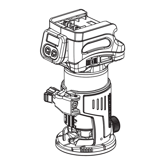
- Page 1 20V BRUSHLESS DIGITAL COMPACT ROUTER 241-0340 OPERATOR’S MANUAL CAUTION: To Reduce The Risk Of Injury, User Must Read And Understand Operator's Manual. Save These Instructions For Future Reference. For questions about this product, please call 1-866-915-8626...
-
Page 2: Table Of Contents
TABLE OF CONTENTS IMPORTANT SAFETY INSTRUCTIONS SPECIFICATIONS FUNCTION ASSEMBLY OPERATION MAINTENANCE PARTS LIST SCHEMATIC DRAWING... -
Page 3: Important Safety Instructions
IMPORTANT SAFETY INSTRUCTIONS 6. If operating a power tool in a damp WARNING: location is unavoidable, use a ground-fault When using electric tools, machines or circuit interrupter (GFCI) protected supply. equipment, basic safety precautions should Use of a GFCI reduces the risk of electric shock. electric shock, and personal injury. - Page 4 IMPORTANT SAFETY INSTRUCTIONS ensure that these are connected and 7. Use the power tool, accessories, tool bits, properly used. Use of these devices can etc. in accordance with these instructions, reduce dust-related hazards. taking into account the working conditions and the work to be performed. Use of the power tool for operations different from those intended could result in a hazardous situation.
- Page 5 IMPORTANT SAFETY INSTRUCTIONS 15.Do not smear the tool base carelessly SPECIFIC SAFETY RULES with thinner, gasoline, oil or the like. They FOR ROUTER may cause cracks in the tool base. 1.Hold power tool by insulated gripping 16.Use trimmer bits of the correct shank surfaces, because the cutter may contact diameter suitable for the speed of the tool.
-
Page 6: Specifications
SPECIFICATIONS Variable speed: 10,000-30,000 RPM (no-load) Collet capacity: 1/4", 3/8" Base diameter: 3-1/2” Base opening: 1-3/8" Plunge depth: 7/8” Contents: router motor, xed base, 1/4" collet, 3/8" collet, roller guide, straight edge guide, dust hood attachment, wrench, and instruction manual FUNCTION 1. -
Page 7: Operation
OPERATION TO ATTACH THE BATTERY PACK SPEED ADJUSTING DIAL 1. Make sure that the router tool is turned The rotation speed of the tool can be off. changed by turning the speed adjusting 2. Align the raised rib on the battery pack dial. - Page 8 OPERATION INSTALLING OR REMOVING ROUTER BIT 2. Close the lock lever. NOTICE: Do not tighten the collet nut 3. Attach the dust nozzle to the trimmer without inserting the bit. The collet cone base, and then tighten the thumb screw. may break.
- Page 9 OPERATION 4. Move the tool with the straight guide NOTE: Before cutting on the actual workpiece, it is recommended to make a If the distance (A) between the side of the sample cut. The proper feed speed depends workpiece and the cutting position is too on the trimmer bit size, the kind of workpiece, wide for the straight guide, or if the side of and depth of cut.
- Page 10 OPERATION USING THE ROLLER GUIDE For cutting circles between 4-5/8" and 8-11/16" in radius. ■ Fig. 11: 1. Wing nut 2. Guide plate 3. Straight guide 4. Center hole 5. Bolt Fig.13 ■ (Fig. 13)The trimmer guide allows for trimming the curved side like veneers for furniture by moving the guide roller along the side of the workpiece.
-
Page 11: Maintenance
MAINTENANCE WARNING: Before cleaning 2. Inspect the screws periodically. If the performing any maintenance, the tool should screws loosen, tighten them immediately, to be unplugged from the power supply. avoid serious accident. 3. Clean all parts of the tool; clean dust and WARNING: If the supply cord debris from vents. -
Page 12: Parts List
PARTS LIST No. Description Qty. No. Description Qty. 1 Screws ST4×16 19 Aluminum housing 2 Label 20 Knob 3 Left housing 21 Spring 4 Battery clip assembly 22 Pin 5 PCBA 23 Chuck 6 Switch Label 24 Nut 7 Switch 25 Knob 8 Display cover 26 Shim 6.5x12x1... -
Page 13: Schematic Drawing
SCHEMATIC DRAWING Page 12... - Page 14 (3) years from the date of original purchase, simply bring the tool with the original sales receipt back to your nearest MENARDS® retail store. At its discretion, MASTERFORCE® agrees to have the tool or any defective part(s) repaired or replaced with the same or similar MASTERFORCE® product or part free of charge, within the stated warranty period, when returned by the original purchaser with original sales receipt.
- Page 15 © 2021 Menard, Inc., Eau Claire, WI 54703 04/2024...
Need help?
Do you have a question about the 241-0340 and is the answer not in the manual?
Questions and answers