
Related Manuals for MasterForce 240-0065


Summary of Contents for MasterForce 240-0065
- Page 1 12" Drill Press (Variable Speed) 240-0065 OPERATOR’S MANUAL CAUTION: To Reduce The Risk Of Injury, User Must Read And Understand Operator’s Manual. Save These Instructions For Future Reference.
-
Page 2: Table Of Contents
TABLE OF CONTENTS Safety Symbols ................. Page 2 Safety Instructions ..............Page 3 Overview ................... Page 7 Specifications ................Page 8 Assembly and Adjustments............Page 8 Operation..................Page 15 Maintenance ................Page 17 Troubleshooting ................ Page 18 Accessories ................Page 21 Warranty.................. -
Page 3: Safety Symbols
SAFETY SYMBOLS Some of the following symbols may be used on your tool. Please study them and learn their meaning. proper interpretation of these symbols will allow you to operate the tool better and safer. Symbol Name Designation / Explanation Volts Voltage Amperes... -
Page 4: Safety Instructions
SAFETY INSTRUCTIONS Page 3... - Page 5 SAFETY INSTRUCTIONS GENERAL SAFTY RULES 13. NEVER STAND ON A TOOL. Serious injury could result if the tool tips or is Safety is a combination of common sense, accidentally hit. staying alert, and knowing how your bench drill DO NOT store anything above or near the tool. press works.
- Page 6 SAFETY INSTRUCTIONS LASER SAFETY chuck before turning power ON. ADJUST the table or depth stop to avoid The laser light beam used in this system is Class drilling into the table. I. These lasers do not normally present an optical 10.
- Page 7 SAFETY INSTRUCTIONS Make sure your extension cord is properly wired and in good condition. Always replace a FIG.A damaged extension cord or have it repaired by a qualified person before using it. Protect your extension cords from sharp objects, excessive heat and damp or wet areas.
-
Page 8: Overview
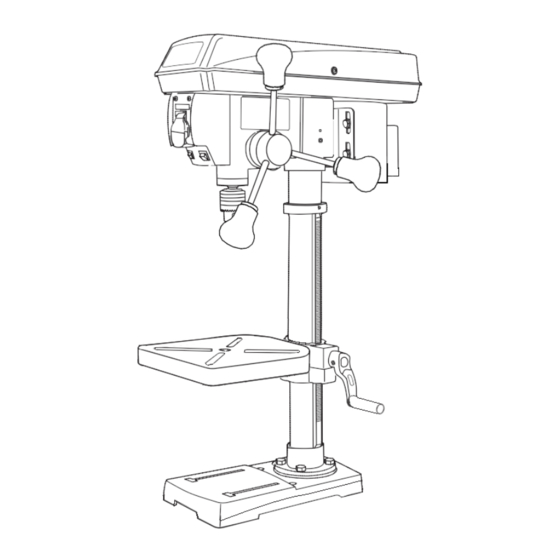
OVERVIEW FIG.1 A Digital speed readout K Crank handle B Large ON/OFF switch L Column support C Depth scale M Base D Chuck N Table lock bolt E Table O Bevel scale F Large, heavy-duty feed handles P Laser line ON/OFF switch G Housing cover screw Q LED work light switch H Housing cover... -
Page 9: Specifications
SPECIFICATIONS BENCH DRILL PRESS WITH LASER LINE MODEL NO.: RDM1603BNV MOTOR: 120V 60 Hz POWER: 550W, 4.6Amp SPEED: 530-3100RPM SWING: 12" (305mm) SPINDLE TAPER: CHUCK CAPACITY: 1/8–5/8" (3–16 mm) QUILL DIAMETER: 2 3/5" (65 mm) STROKE: 3 1/8" (80 mm) CAPACITY: 6"... - Page 10 ASSEMBLY AND ADJUSTMENTS A Head/motor assembly H Hex head bolts (4) B Column assembly and table Table crank handle bracket Hex keys (2) C Table K Feed and speed handles (4) D Base L LED bulb E Chuck M Table adjustment wrench F Chuck key N Wedge G Table lock handle...
- Page 11 ASSEMBLY AND ADJUSTMENTS Drill press head to column (Fig. 5) Speed handle (Fig. 7) 1. Insert the feed handle (1) into the threaded The drill press head is opening on the speed hub (2). heavy. To avoid injury, two people should lift 2.
- Page 12 ASSEMBLY AND ADJUSTMENTS FIG.11 DISCONNECT THE BENCH DRILL PRESS FROM THE POWER SOURCE BEFORE INSTALLING, ADJUSTING, OR REMOVING THE CHUCK. FIG.10 To remove the chuck (Fig. 11) 1. Turn the feed handles (1) to lower the chuck (2) to the lowest position. 2.
- Page 13 ASSEMBLY AND ADJUSTMENTS in the rack collar. 3. Insert a drill bit (4) into the chuck far enough to obtain maximum gripping of the chuck jaws. 2. Tighten the support lock before drilling. 4. Centre the drill bit in the chuck jaws before FIG.13 final tightening of the chuck.
- Page 14 ASSEMBLY AND ADJUSTMENTS a. Using a 3 mm hex key, turn the laser FIG.16 adjustment set screws (3) counter-clockwise. b. Rotate the laser light housing (4) until the two laser lines intersect where the drill meets the workpiece. DO NOT stare directly at the laser lines.
- Page 15 ASSEMBLY AND ADJUSTMENTS handle is moved. FIG.19 Note: See page 17 for information on the variable speed function of this bench drill press. 1. Remove the screw that secures the housing cover (1). Open the housing cover. 2. Remove the belt (2) from the housing cover if it is broken.
-
Page 16: Operation
OPERATION Position the table and workpiece (Fig. 22) FIG.21 1. Always place a piece of backup material (1) (wood, plywood, etc.) on the table underneath the workpiece (2). This will prevent splintering on the underside of the workpiece as the drill bit breaks through. - Page 17 OPERATION Depth scale method (Fig. 24) FIG.23 1. Make sure the 0 (" or mm) mark on the depth gauge rests at the top edge of the metal support (3) when the quill is fully retracted. 2. Put the workpiece on the table, and raise the table until the tip of the drill bit just touches the top of the workpiece.
-
Page 18: Maintenance
OPERATION than harder materials. See right speadsheet for increase or decrease the speed when operating, recommended speeds for the workpiece material. raise or lower the speed handle (1). Use the following table to determine the FIG.26 recommended speed for the drill size you are using and the type of material you are to drill. -
Page 19: Troubleshooting
TROUBLESHOOTING PROBLEM PROBABLE CAUSE REMEDY 1. Incorrect belt tension. • Adjust the belt tension. See "To replace the belt" in ADJUSTMENTS. 2. Dry spindle. • Lubricate the spindle. See MAINTENANCE Noisy operation. section. 3. Loose spindle pulley. • Tighten the retaining nut on the pulley insert. - Page 20 TROUBLESHOOTING PROBLEM PROBABLE CAUSE REMEDY The workpiece 1. No backup material under • Always use a backup material. See splinters on the the workpiece. "Position the table and workpiece" in OPERATION. underside. The workpiece is 1. Not supported or clamped •...
- Page 21 NOTES Page 20...
-
Page 22: Accessories
ACCESSORIES Page 21... - Page 23 ACCESSORIES Key No. Description Key No. Description Pan Head Screw, M4x8 Handle Base Support clamp Pin, 5x16 Hex socket screw, M8x8 Ring Hex bolt, M16x35 Shaft-pinion Support column Hex bolt, M8x25 Hex bolt, M10x30 Washer Crank Motor Hex. socket screw, M6x10 Key, C4x76 Worm Hex bolt, M8x12...
- Page 24 ACCESSORIES Key No. Description Key No. Description Washer Key, 3x6 Retaining ring 24 Handle seat Retaining ring 14 Self-lock nut Motor pulley Dishing spring Cord-power (Ame) Washer foam Cord-motor Bushing rubber Allen wrench S3 Nut, M5 Allen wrench S4 Receiver seat Collar-rack Receiver Pin Φ2.5x12...
-
Page 25: Warranty
MENARDS® retail store. At its discretion, MASTERFORCE™ agrees to have the tool or any defective part(s) repaired or replaced with the same or similar MASTERFORCE™ product or part free of charge, within the stated warranty period, when returned by the original purchaser with original sales receipt. - Page 26 09/2017 © 2017 Menard, Inc., Eau Claire, WI 54703...
Need help?
Do you have a question about the 240-0065 and is the answer not in the manual?
Questions and answers