Table of Contents
Advertisement
Quick Links
Download this manual
See also:
Installation Manual
Advertisement
Table of Contents

Related Manuals for D-Link AirSpot DSA-5100


Summary of Contents for D-Link AirSpot DSA-5100
- Page 1 D-Link Airspot DSA-5100 Enterprise Gateway Manual April 2006 v. 1.03 Building Networks for People...
-
Page 2: Table Of Contents
Contents Package Contents ................3 Introduction...................4 Front Panel ...................5 Rear Panel ...................5 Features ....................6 Sample Network Setup .................8 Installation ....................9 Setting Up the DSA-3100 ..............9 TCP/IP Network Setting ..............10 Internet Access Configuration ............11 Using the Configuration Utility ............13 Networking Basics ................63 Technical Specifications ..............77 Technical Support ................78 Warranty .....................81... -
Page 3: Package Contents
Package Contents D-Link DSA-5100 Airspot Enterprise Gateway CD-ROM with manual Quick Installation Guide Three (3) CAT5 UTP/Straight-through (Ethernet) cables One (1) CAT5 UTP/Cross-over cable One (1) Console cable 1 PC-Style Power cable to 110 VAC If any of the above items are missing, please contact your reseller. -
Page 4: Introduction
Ethernet, Fast Ethernet or an IEEE 802.11 wireless LAN (WLAN) separately and simultaneously. The DSA-5100 can be configured with a standard HTML browser (i.e., Internet Explorer, or Netscape Navigator) operating on Windows 98SE/Me/2000/XP, Macintosh OS 9, Macintosh OS X (v10.1.5 or later), Linux, or Pocket PC 2000/2002. The DSA-5100 allows the operator to offer wired or wireless networking services and access to the Internet when used with a switch or wireless access point respectively. -
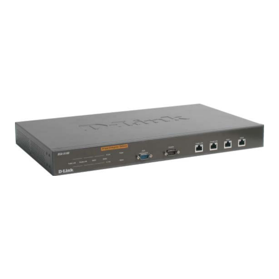
Page 5: Front Panel
Status LED - system settings. Public LAN Port- Upon starting up the Can be connected to the DSA-5100, this LED open network environment will blink momentarily. managed by the system or A solid light indicates WLAN, and requires that the system is authentication before logging ready. -
Page 6: Features
Provides several DoS protection mechanisms Customizable packet filter rules Customizable walled garden (free surfing area) The DSA-5100 supports at least 400 on-line users concurrently Supports POP3, RADIUS, and LDAP authentication mechanisms Supports two or more authentication mechanisms simultaneously Can set the time for the user to logon to the system Can set the user’s idle time... - Page 7 Features (continued) Permits or refuses all connections when the WAN interface fails Supports Web-based logon Provides several friendly logout methods Supports RADIUS account roaming Provides online status monitoring and history traffic Supports SSL encrypted web administration interface and user logon interface Customizable user login &...
-
Page 8: Sample Network Setup
A Sample Network Setup... -
Page 9: Installation
Use one of the supplied straight-through cables to connect the DSA-5100 to the network not managed by the DSA-5100 system (such as and ATU router for ADSL, the Ethernet port of a cable modem, or a switch or hub on a LAN). -
Page 10: Tcp/Ip Network Setting
For Windows 98SE/ME/2000/XP, you need to keep the default TCP/IP settings (“obtain IP and DNS address automatically”) to communicate with the DSA-5100. The DSA-5100 leases DHCP addresses from the Public and Private LAN ports for ease of configuration. For Non-Server Windows operating systems, the default setting for TCP/IP is “DHCP client,”... -
Page 11: Internet Access Configuration
Internet Access Configuration To configure your PCs to use the DSA-5100 for Internet access, follow this procedure. For Windows 98SE/2000 Please select Start Menu - Control Panel - Internet Options. Select the Connection tab, and click the Setup button. - Page 12 Internet Access Configuration (continued) Select “I want to set up my Internet connection manually, or I want to connect through a local Area network (LAN)” and click Next. Select “I connect through a local area network (LAN)” and click Next. Ensure all of the boxes on the local area network Internet configuration screen are unchecked.
-
Page 13: Using The Configuration Utility
Using the Configuration Utility To configure the DSA-5100, connect a computer to the Private LAN port of the DSA-5100 with the supplied crossover Ethernet cable. First, disable the Access the Internet using a proxy server function. To disable this function, go to Control Panel > Internet Options > Connections >... - Page 14 Using the Configuration Utility (continued) System Configuration > Configuration Wizard The System Configuration>Configuration Wizard screen will appear if you logged in as admin. For more information on the Setup Wizard, please see the Installation Guide, included with your purchase. You can access the configuration features from this window.
- Page 15 Using the Configuration Utility (continued) System Configuration > System Information System DSA-5100 is the default system name. You may wish to rename it to Name: indicate your company, department, or the service you would like to provide. Administrator You can edit the System Administrator’s information here (e.g., name, Info: phone number, and e-mail).
- Page 16 Please specify the IP address or DNS name of an SNTP server on the system configuration interface. Time Zone: Set up the time zone for the DSA-5100. The default is GMT+08:00. (Taipei) Set Device Date and Time: Manually specify system time.
- Page 17 Using the Configuration Utility (continued) System Configuration > WAN1 Configuration > Static IP Mode Static IP Address: IP address: Enter the IP address provided to you by your ISP (Required). Enter the subnet mask provided to you by your ISP. All Subnet mask: devices on the network must share the same subnet...
- Page 18 Using the Configuration Utility (continued) System Configuration > WAN1 > Dynamic IP Address Select this option if there is a DHCP server on the network or to obtain an IP address automatically from your ISP. System Configuration > WAN1 > PPPoE Most DSL users will select this option.
- Page 19 Using the Configuration Utility (continued) System Configuration > WAN2 > Static IP Address Static IP Address: IP address: Enter the IP address provided to you by your ISP. Enter the subnet mask provided to you by your ISP. All Subnet devices on the network must share the same netmask.
- Page 20 DNS address) to connect to the Internet; no matter what the IP address at the user end is, you can access the network resources properly and authenticate through the DSA-5100. Note: This function can only be activated under NAT. 2. Mobile IP: If you construct a network environment using several DSA-5100s, a user can use the same group of IP configurations.
- Page 21 Using the Configuration Utility (continued) System Configuration > Public LAN > Public LAN Configuration (continued) The system will confirm if you want to Enable VLAN; please click Enable to continue. After you click Enable, the following screen will appear. See the following description for details.
- Page 22 (these IP addresses must belong to the same network as the VLAN Port) will be converted into the IP address of the WAN1 Port by the DSA-5100 and connected to the outside. Router Mode: All IP addresses externally connected through the VLAN Port use their own IP address for external connections.
- Page 23 Using the Configuration Utility (continued) Public LAN > VLAN > DHCP Configuration (continued) Enable DHCP Server (continued): DHCP Scope Start IP Enter the starting IP address of the pool, from which the Address: DHCP server will assign to the DHCP-enabled devices (clients) on the network.
- Page 24 Using the Configuration Utility (continued) Public LAN > VLAN > DHCP Configuration (continued) Enable DHCP Server (continued): If you want to use the Reserved IP Address List function, please Reserved IP click the hyperlink of the Reserved IP Address List on the Address List: management interface.
- Page 25 Using the Configuration Utility (continued) System Configuration > Private LAN Configuration For an explanation of each field on this screen, please see the previous screen: System Configuration > Public LAN Configuration.
- Page 26 Using the Configuration Utility (continued) User Authentication User Authentication allows the DSA-5100 owner/operator to control who has or does not have access to the Internet. The DSA-5100 can support five different authentication types simultaneously. User Authentication > Authentication Policies The DSA-5100 provides a simple interface to allow the administrator to easily complete the complicated management setup.
-
Page 27: Authentication Server
Using the Configuration Utility (continued) Edit Authentication Policies Authentication Policy: Displays the system’s preferred authentication method. Policy ID: Select the policy you wish to edit here. Set as Default: Make this selection to set the policy you have chosen to be the default Authentication policy. - Page 28 Using the Configuration Utility (continued) Authentication Server> Exception Configuration Attribute: After the authentication, the DSA-5100 will obtain the user’s attributes related to the authenticated server. The administrator can use certain attributes as the management rule for the setup. Logic: Logic options include equal to, not equal to, larger than, smaller than, and include.
- Page 29 Using the Configuration Utility (continued) Authentication Methods>Local>Local Users List The user’s account information is stored in the DSA-5100. If you need to manage the user’s account, please click the hyperlink Local Users List on the Authentication Server interface to enter into the Account Management Interface, shown below.
- Page 30 Using the Configuration Utility (continued) Authentication Methods > Local > Local Users List > Add User> Edit Account Edit Account: Edit the account here. Local Users List > Add User> Upload User Account Upload User Account: Click the Browse button to select the text file for the user account.
- Page 31 The authentication port for the RADIUS server. Accounting Port: The port reading the accounting information. Secret Key: This is for encryption and decryption, must be configured on both RADIUS Server and DSA-5100. Accounting Service: Select to enable the accounting service (optional).
- Page 32 Using the Configuration Utility (continued) Authentication Methods > LDAP You may configure a primary and a secondary server for LDAP authentication. If you select the LDAP authentication method, type in the IP Address (Domain Name), Port number, the Base DN Data of LDAP Server, and select one of the Account Attribute Type.
- Page 33 Using the Configuration Utility (continued) External Web Server The DSA-5100 supports an external web server function (including database) which enables a user to put the login page on an external web server, and change the login page anytime. Protocol: Choose from http or https (http protocol is selected here).
- Page 34 Using the Configuration Utility (continued) User Authentication>Edit Group Configuration Group Name Guest: Assign a group name; Guest is selected here. Firewall Profile: Select the firewall profile for this group. Specific Route Profile: Select the route profile for this group. Schedule Profile: Select a schedule for this profile.
- Page 35 Using the Configuration Utility (continued) User Authentication>Black List Configuration Username: Enter the username to be blacklisted here. Remark: Add a comment (optional). Apply: Click Apply to add the user to the blacklist. Previous: Click Previous to return to the Black List Configuration.
- Page 36 Using the Configuration Utility (continued) User Authentication>Black List Configuration>Delete a User Delete: To delete a user, check the box in the Delete column, and then click the Delete button. No notification will appear to confirm the deletion. User Authentication>Guest User Configuration Enable: Select Enable to activate the Guest Account feature for visitors.
- Page 37 User Authentication>Roaming Configuration The system provides Airpath and Pronto Service for roaming. Set up the parameters in this page to let the user of the Airpath and Pronto Service use the DSA-5100. Click Apply. Caution: The login location is the same as the location of the account’s origin.
- Page 38 Device Name: FQDN (Fully-Qualified Domain Name). This is the domain name of the DSA-5100 as seen on client machines connected on LAN ports. A user on client machine can use this name to access DSA-5100 instead of its IP address.
- Page 39 2. Pronto: DSA-5100 can also be configured for Pronto Networks and accept roaming users from Pronto Networks To facilitate DSA-5100 for Pronto registered users, admini- strator simply enables Pronto Service and enters basic Pronto Network Server information. DSA-5100 will automatically configure itself and register with Pronto Networks using these information.
- Page 40 Using the Configuration Utility (continued) Primary / Backup Server (setting from Pronto): > Authentication Server IP: IP address of Pronto RADIUS server > Authentication Port: Pronto RADIUS server authentication port > Authentication Secret Key: Pronto RADIUS server authentication secret key >...
- Page 41 When the WAN connection fails, the user login screen will be redirected to the URL. The DSA-5100 can detect if the WAN connection fails by using an ICMP echo mechanism to ping the default gateway and the DNS server periodically.
- Page 42 Using the Configuration Utility (continued) User Authentication>Upload File Private Key/ Certification: The DSA-5100 allows the user to upload certification. (The key must be in key format and the certificate must be in certificate format.) File Name: Enter the filename of the logon Web...
- Page 43 To provide a custom user login error page, please specify the file name to upload to the DSA-5100. If you want to get back to the Error page, click Use Default Page. If you want to display the Login Error Page, click Preview.
- Page 44 Using the Configuration Utility (continued) The DSA-5100 provides three kinds of Profile configurations, including Firewall Profile, Specific Route Profile, and Login Schedule Profile. Group Profile > Firewall Profile Global is the default setting. Use the Global setting to apply parameters to all users.
- Page 45 Using the Configuration Utility (continued) Group Profile > Firewall Profile>Edit Filter Rule (continued) Source MAC: MAC address of the Network component sending the request. Source (Destination) Interface: Source (Destination) Interface includes 4 interfaces: WAN1, WAN2, Public LAN, and Private LAN. Select ALL to apply to all four interfaces. Source (Destination) IP Address: IP address of the Network component sending (receiving) the request.
- Page 46 Caution: To allow two machines to access data from each other, add a static route to the next connected router in order to send all packets back to the DSA-5100. After the static route is changed, it is necessary to restart the DSA-5100 to enable the static route.
- Page 47 The user’s login schedule can be set. After durations are defined, please click Apply to save the settings in the DSA-5100. Network Configuration > Network Address Translate If you have several IP addresses, you can assign them to the WAN port of the system.
- Page 48 Using the Configuration Utility (continued) Network Configuration > Network Address Translate (continued) Port and IP Redirect When any user attempts connect destination defined in this interface, connection packet will be converted to the c o r r e s p o n d i n g destination.
- Page 49 Using the Configuration Utility (continued) Network Configuration > MAC Pass Through Configuration You can also bypass authentication based on the MAC address at the user end. Please enter the MAC address of the user on this interface. This system permits at most 100 MAC addresses to have network access rights...
- Page 50 Using the Configuration Utility (continued) Network Configuration > Monitor IP List (continued) Notify Configuration From: The e-mail address of the administrator server in charge of the monitoring. The e-mail address of the user of the IP address under the monitoring. Interval: The time interval to send the e-mail report.
- Page 51 Network Configuration > Proxy Server Properties Internal Proxy Server: Enable this function to configure the DSA-5100 as a proxy server. External Proxy Server: By default, only port 80 is allowed. It will appear on the login Web page. If you have built a Proxy Server in your network environment, and the user’s browser is set to...
- Page 52 Using the Configuration Utility (continued) Utilities > Change Password DSA-5100 provides 2 built-in user accounts: admin and manager. admin: This user is the administrator in the DSA-5100. manager: This user has the right to manage a user account, the admin functions are denied.
- Page 53 Using the Configuration Utility (continued) Utilities > Backup/Restore Strategy This utility provides the backup function, and the ability to restore backup settings. This function can also restore the factory default settings to the system. Create Backup Image: Create: Generate the backup (image) file. Restore Settings From File: Browse: Browse for the backup file.
- Page 54 Using the Configuration Utility (continued) Utilities > Firmware Upgrade You may obtain firmware upgrades from D-Link’s support website: http://support.dlink.com Warning: A Firmware upgrade may cause data loss on setup. Please refer to the version description to see if there is any limitation before upgrading your firmware.
- Page 55 Using the Configuration Utility (continued) Status> System Status You can use this function to get the overview of the system status. Please refer to the following example.
- Page 56 When the connection at WAN is abnormal (WAN Fail), all online users can log on to the network. Manage It permits a specific IP address to set up the DSA-5100 Remote Management from the WAN1 port. SNMP Do not enable SNMP management function.
- Page 57 Using the Configuration Utility (continued) Status> Interface Status...
- Page 58 Using the Configuration Utility (continued) Status> Interface Status (continued)
- Page 59 Status > Traffic History Notify Configuration: History Email: The DSA-5100 will save the history into the internal DRAM. If you want to automatically send the history to your E-mail address, please enter your E-mail address in the History E-mail column.
-
Page 60: Console Interface
The DSA-5100 provides a serial interface for the manager to handle different problems and situations for the operation. To link to the Console interface of the DSA-5100, you need a null modem cable (provided). The terminal simulation program that you use, such as the Hyperterminal, should be set to the parameter value of 115200,8,n,1. - Page 61 Displays each network interface setting including the MAC address, IP address, and netmask. Display the routing table The internal routing table of the DSA-5100 is displayed to assist the confirmation of the successful setup of another static route on the DSA-5100. Display ARP table The internal ARP table of the DSA-5100 is displayed.
- Page 62 DSA-5100’s setup. When using a null modem to connect to the DSA-5100 console, you do not need to enter the administrator’s password. When SSH is used to connect the DSA-5100, the username is admin and the default password is also admin. The set values are the same as those for the Web management interface.
-
Page 63: Networking Basics
Networking Basics Using the Network Setup Wizard in Windows XP In this section you will learn how to establish a network at home or work, using Microsoft Windows XP. Note: Please refer to websites such as http://www.homenethelp.com http://www.microsoft.com/windows2000 for information about networking computers using Windows 2000, ME or 98SE. - Page 64 Networking Basics (continued) Please follow all the instructions in this window: Click Next. In the following window, select the best description of your computer. If your computer connects to the internet through a gateway/router, select the second option as shown. Click Next.
- Page 65 Networking Basics (continued) Enter a Computer description and a Computer name (optional.) Click Next. Enter a Workgroup name. All computers on your network should have the same Workgroup name. Click Next.
- Page 66 Networking Basics (continued) Please wait while the Network Setup Wizard applies the changes. When the changes are complete, click Next. Please wait while the Network Setup Wizard configures the computer. This may take a few minutes.
- Page 67 Networking Basics (continued) In the window below, select the option that fits your needs. In this example, Create a Network Setup Disk has been selected. You will run this disk on each of the computers on your network. Click Next. Insert a disk into the Floppy Disk Drive, in this case drive A.
- Page 68 Networking Basics (continued) Please read the information under Here’s how in the screen below. After you com- plete the Network Setup Wizard you will use the Network Setup Disk to run the Network Setup Wizard once on each of the computers on your network. Click Next.
- Page 69 Networking Basics (continued) Please read the information on this screen, then click Finish to complete the Network Setup Wizard. The new settings will take effect when you restart the computer. Click Yes to restart the computer. You have completed configuring this computer. Next, you will need to run the Net- work Setup Disk on all the other computers on your network.
- Page 70 Networking Basics (continued) Naming your Computer To name your computer In Windows XP, please follow these directions: Click Start (in the lower left corner of the screen). Right-click on My Computer. Select Properties. Select the Computer Name Tab in the System Properties window.
- Page 71 Networking Basics (continued) Naming your Computer (continued) In this window, enter the Computer name. Select Workgroup and enter the name of the Workgroup. All computers on your network must have the same Workgroup name. Click OK. Checking the IP Address in Windows XP The adapter-equipped computers in your network must be in the same IP Address range (see Getting Started in this manual for a definition of IP Address Range.) To check on the IP Address of the adapter, please do the following:...
- Page 72 Networking Basics (continued) Checking the IP Address in Windows XP (continued) This window will appear. Click the Support tab. Click Close. Assigning a Static IP Address in Windows XP/2000 Note: Residential Gateways/Broadband Routers will automatically assign IP Addresses to the computers on the network, using DHCP (Dynamic Host Configuration Protocol) technology.
- Page 73 Networking Basics (continued) Assigning a Static IP Address in Windows XP/2000 (continued) Double-click on Network Connections. Right-click on Local Area Connections. Double-click on Properties.
- Page 74 Networking Basics (continued) Assigning a Static IP Address in Windows XP/2000 Click on Internet Protocol (TCP/IP). Click Properties. Input your IP Address and subnet mask. (The IP Addresses on your network must be within the same range. For example, if one computer has an IP Address of 192.168.0.2, the other computers should have IP...
- Page 75 Networking Basics (continued) Assigning a Static IP Address with Macintosh OSX Go to the Apple Menu and se- lect System Preferences. cClick on Network. Select Built-in Ethernet in the Show pull-down menu. Select Manually in the Configure pull-down menu. Input the Static IP Address, the Subnet Mask and the Router IP Address in the appropriate fields.
- Page 76 Networking Basics (continued) Selecting a Dynamic IP Address with Macintosh OSX Go to the Apple Menu and select System Preferences. Click on Network. Select Built-in Ethernet in the Show pull-down menu. Select Using DHCP in the Configure pull-down menu. Click Apply Now. The IP Address, Subnet mask, and the Router’s IP Address will appear in a few...
- Page 77 Networking Basics (continued) Checking the Wireless Connection by Pinging in Windows XP/2000 Note: The following illustrations are examples only. The IP Address that you are pinging may be different from those in the following examples. Go to Start > Run > type cmd.
-
Page 78: Technical Specifications
Technical Specifications Functions Provided 4 10/100Mbps Fast Ethernet ports for dual WAN connection, trusted LAN connection and untrusted LAN connection Manages up to 250 user accounts via the internal user account database ID/Password based authentication and authorization- Can be combined with MAC Address locking to provide stricter access control POP3, RADIUS and LDAP external authentication mechanism support - Only one of these can be selected at a time... - Page 79 Technical Specifications (continued) Device Ports WAN1 port: 10/100Mbps Fast Ethernet WAN2 port: 10/100Mbps Fast Ethernet Private LAN port: 10/100Mbps Fast Ethernet connects to workstations & servers that do not need authentication Public LAN port: 10/100Mbps Fast Ethernet connects to workstations & devices that need authentication Console port: RS-232 (default set to 115200, n, 8, 1, no flow control) Power Supply...
- Page 80 Support echni cal Support You can find software updates and user documentation on the D-Link website. D-Link provides free technical support for customers within the United States and within Canada for the duration of the warranty period on this product.
-
Page 81: Warranty
D-Link’s sole obligation shall be to repair or replace the defective Hardware during the Warranty Period at no charge to the original owner or to refund at D-Link’s sole discretion. Such repair or replacement will be rendered by D-Link at an Authorized D-Link Service Office. The replacement Hardware need not be new or have an identical make, model or part. - Page 82 The customer is responsible for all in-bound shipping charges to D-Link. No Cash on Delivery (“COD”) is allowed. Products sent COD will either be rejected by D-Link or become the property of D- Link. Products shall be fully insured by the customer and shipped to D-Link Systems, Inc., 17595 Mt.
- Page 83 Trademarks: D-Link is a registered trademark of D-Link Systems, Inc. Other trademarks or registered trademarks are the property of their respective manufacturers or owners.
-
Page 84: Appendix Windows Tcp/Ip Setup
Appendix Windows TCP/IP Setup If you have not changed the factory default settings of the DSA-5100 in Windows XP/ 2000/ME/98SE TCP/IP, it is not necessary to make any modification here. With the factory default settings, the DSA-5100 will automatically assign an appropriate IP address (and related information) to each PC after the PC has been booted. - Page 85 Click Properties. Using DHCP If you want to use DHCP, please select Obtain an IP Address Automatically, which is also the default setting of Windows. Reboot the PC to make sure an IP address is obtained from the DSA-5100.
- Page 86 If the DNS Server column is blank, please click Enable DNS. Enter the DNS address or the DNS address provided by your ISP. Click OK. Select the Gateway tab, and enter the IP address of the DSA-5100. Click Add.
- Page 87 Appendix Windows TCP/IP Setup Check the TCP/IP Setup of Windows 2000 Select Start> Control Panel> Network and Dial-up Connections Right-click Local Area Connection. Select Properties.
- Page 88 Select Internet Protocol(TCP/IP). Click Properties. Using DHCP If you want to use DHCP, please select Obtain an IP Address Automatically, which is also the default setting. Reboot the PC to make sure an IP address is obtained from the DSA-5100.
- Page 89 If you have completed the setup for your PC, please inform the network administrator before modifying the following setup. Click Advanced in the TCP/IP properties. Select the IP Settings tab. Click Add. Enter the IP address of the DSA-5100 in the Default Gateways column. Click Add.
- Page 90 Appendix Windows TCP/IP Setup Check the TCP/IP Setup of Windows 2000 (continued) Click Using the following DNS Server Address. Enter address provided by your ISP. Click OK. Check the TCP/IP Setup of Windows XP Select Start > Control Panel > Network Connection.
- Page 91 Appendix Windows TCP/IP Setup Check the TCP/IP Setup of Windows XP (continued) Right-click Local Area Connection. Select Properties. Select the General tab. Select Internet Protocol (TCP/IP). Click Properties.
- Page 92 Appendix Windows TCP/IP Setup Check the TCP/IP Setup of Windows XP (continued) If you want to use DHCP, please select Obtain an IP Address Automatically. Click OK. Using the Static IP Address Click Advanced.
- Page 93 Windows TCP/IP Setup Check the TCP/IP Setup in Windows XP Click the IP Settings tab. Enter the IP address of the DSA-5100 in the Default Gateways column. Click Add. Click OK. If the DNS Server field is blank, select Use the following DNS Server Addresses.
Need help?
Do you have a question about the AirSpot DSA-5100 and is the answer not in the manual?
Questions and answers