Vega VEGAPULS C 21 Operating Instructions Manual
Radar sensor for continuous level measurement
Hide thumbs
Also See for VEGAPULS C 21:
- Operating instructions manual (64 pages) ,
- Operating instructions manual (56 pages) ,
- Operating instructions manual (60 pages)

Related Manuals for Vega VEGAPULS C 21


Summary of Contents for Vega VEGAPULS C 21
- Page 1 Operating Instructions Radar sensor for continuous level measurement VEGAPULS C 21 Two-wire: 4 … 20 mA/HART Document ID: 58341...
-
Page 2: Table Of Contents
Connect the PC ......................28 Parameter adjustment ....................29 Save parameter adjustment data..................30 10 Adjustment menu ........................31 10.1 Menu overview ....................... 31 10.2 Description of the applications ..................33 VEGAPULS C 21 • Two-wire: 4 … 20 mA/HART... - Page 3 14.1 Technical data ........................ 49 14.2 Dimensions ........................55 14.3 Industrial property rights ....................56 14.4 Licensing information for open source software ............. 56 14.5 Trademark ........................56 Editing status: 2024-09-30 VEGAPULS C 21 • Two-wire: 4 … 20 mA/HART...
-
Page 4: About This Document
Symbols used Document ID This symbol on the front page of this instruction refers to the Docu- ment ID. By entering the Document ID on www.vega.com you will reach the document download. Information, note, tip: This symbol indicates helpful additional infor- mation and tips for successful work. -
Page 5: For Your Safety
During work on and with the device, the required personal protective equipment must always be worn. Appropriate use VEGAPULS C 21 is a sensor for continuous level measurement. You can find detailed information about the area of application in chapter "Product description". Operational reliability is ensured only if the instrument is properly used according to the specifications in this document as well as pos- sible supplementary instructions. -
Page 6: Mode Of Operation - Radar Signal
Installations in Canada shall comply with the relevant requirements of the Canadian Electrical Code (CEC Part I) (Canada). A Class 2 power supply unit has to be used for the installation in the USA and Canada. VEGAPULS C 21 • Two-wire: 4 … 20 mA/HART... -
Page 7: Product Description
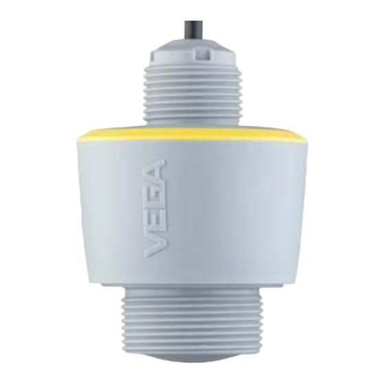
Fig. 1: Components of VEGAPULS C 21 Radar antenna 2 Process fitting Electronics housing Counter nut Mounting thread Connection cable Type label The type label contains the most important data for identification and use of the instrument: • Instrument type • Information about approvals VEGAPULS C 21 • Two-wire: 4 … 20 mA/HART... -
Page 8: Principle Of Operation
Open the VEGA Tools app and enter the serial number under "Documentation". Principle of operation Application area VEGAPULS C 21 is a radar sensor for non-contact, continuous level measurement. It is suitable for liquids and solids in practically all industries. Functional principle The instrument emits a continuous, frequency-modulated radar signal through its antenna. The emitted signal is reflected by the medium... -
Page 9: Packaging, Transport And Storage
Unless otherwise indicated, the packages must be stored only under the following conditions: • Not in the open • Dry and dust free • Not exposed to corrosive media • Protected against solar radiation • Avoiding mechanical shock and vibration VEGAPULS C 21 • Two-wire: 4 … 20 mA/HART... -
Page 10: Accessories
Threaded and hygienic adapters enable simple adaptation of devices with standard threaded fittings to process-side hygiene connections. Mounting strap The mounting accessories are used for stable mounting of the device at the measuring point. The parts are available in various versions and sizes. VEGAPULS C 21 • Two-wire: 4 … 20 mA/HART... -
Page 11: Mounting
The mounting of the device in the bracket is carried out via the supplied G1 counter nut of plastic. Take note of chapter "Mounting instructions" for the recommended distance to the wall. VEGAPULS C 21 • Two-wire: 4 … 20 mA/HART... -
Page 12: Mounting Instructions
This applies particularly if buildup on the vessel wall is expected. In such cases, we recommend repeating the false signal suppression at a later date with existing buildup. VEGAPULS C 21 • Two-wire: 4 … 20 mA/HART... -
Page 13: Reference Plane
The centre of the antenna lens is the beginning of the measuring range and at the same time the reference plane for the min./max. adjustment, see following diagram: Fig. 8: Reference plane Reference plane Inflowing medium Do not mount the instruments in or above the filling stream. Make sure that you detect the medium surface, not the inflowing product. VEGAPULS C 21 • Two-wire: 4 … 20 mA/HART... - Page 14 (0.2 in) out of the socket. Fig. 10: Recommended threaded socket mounting of VEGAPULS C 21 If the reflective properties of the medium are good, you can mount VEGAPULS C 21 on sockets longer than the antenna. The socket end should be smooth and burr-free, if possible also rounded. Note: When mounting on longer nozzles, we recommend carrying out a false signal suppression (see chapter "Parameter adjustment").
- Page 15 In a cylindrical silo with conical outlet, the sensor is mounted anywhere from one third to one half of the vessel radius from the outside wall (see following drawing). VEGAPULS C 21 • Two-wire: 4 … 20 mA/HART...
- Page 16 It can be easily checked with a suitable bubble tube or mechanic's level on the sensor. Fig. 15: Proposal for installation after orientation VEGAPULS C 21 VEGAPULS C 21 • Two-wire: 4 … 20 mA/HART...
- Page 17 Note: If foams lead to measurement errors, you should use the biggest pos- sible radar antennas or as an alternative, sensors with guided radar. VEGAPULS C 21 • Two-wire: 4 … 20 mA/HART...
-
Page 18: Measurement Setup - Flow
Detailed project planning data can be found at the channel manufac- turers and in the technical literature. The following examples serve as an overview for flow measurement. The value given takes into account the block distance. At smaller distances, the measuring accuracy is reduced, see "Technical data". VEGAPULS C 21 • Two-wire: 4 … 20 mA/HART... - Page 19 3 ... 4 h 90° 90° Fig. 17: Flow measurement with rectangular flume: h = max. filling of the max. rectangular flume 1 Overfall orifice (side view) Upstream water Tailwater 4 Overfall orifice (view from tailwater) Khafagi-Venturi flume 3 ... 4 x h 90° Fig. 18: Flow measurement with Khafagi-Venturi flume: h = max. filling of the max. flume; B = tightest constriction in the flume Position sensor 2 Venturi flume VEGAPULS C 21 • Two-wire: 4 … 20 mA/HART...
-
Page 20: Connecting To Power Supply
We recommend to connect the cable screening to ground potential at grounding one end on the supply side when using shielded cable. Wiring plan Wire assignment, con- nection cable Fig. 19: Wire assignment in permanently connected connection cable VEGAPULS C 21 • Two-wire: 4 … 20 mA/HART... -
Page 21: Switch-On Phase
After connection to the power supply, the device carries out a self- test: • Internal check of the electronics • Output signal is set to failure The current measured value is then output on the signal cable. VEGAPULS C 21 • Two-wire: 4 … 20 mA/HART... -
Page 22: Access Protection
"Ac- cess protection". If this document is lost, the emergency device code can be retrieved from your personal contact person after legitimation. VEGAPULS C 21 • Two-wire: 4 … 20 mA/HART... -
Page 23: Storing The Codes In Myvega
"PINs and Codes". This greatly simplifies the use of additional adjust- ment tools, as all Bluetooth access and device codes are automati- cally synchronized when connected to the "myVEGA" account VEGAPULS C 21 • Two-wire: 4 … 20 mA/HART... -
Page 24: Setup With Smartphone/Tablet (Bluetooth)
• Operating system: Android 5.1 or newer • Bluetooth 4.0 LE or newer Download the VEGA Tools app from the "Apple App Store", "Goog- le Play Store" or "Baidu Store" to your smartphone or tablet. Connecting Connecting Start the adjustment app and select the function "Setup". The smart- phone/tablet searches automatically for Bluetooth-capable instru- ments in the area. -
Page 25: Parameter Adjustment
• Navigation section • Menu item display The selected menu item can be recognized by the colour change. Fig. 21: Example of an app view - Setup measured values Enter the requested parameters and confirm via the keyboard or the editing field. The settings are then active in the sensor. Close the app to terminate connection. VEGAPULS C 21 • Two-wire: 4 … 20 mA/HART... -
Page 26: Setup With Pc/Notebook (Bluetooth)
Enter Bluetooth access For authentication, enter in the next menu window the 6-digit code Bluetooth access code: Fig. 22: Enter Bluetooth access code VEGAPULS C 21 • Two-wire: 4 … 20 mA/HART... -
Page 27: Parameter Adjustment
(DTM) according to FDT standard are required. The latest PACTware version as well as all available DTMs are compiled in a DTM Collec- tion. The DTMs can also be integrated into other frame applications according to FDT standard. Fig. 23: Example of a DTM view - Setup, sensor adjustment VEGAPULS C 21 • Two-wire: 4 … 20 mA/HART... -
Page 28: Setup With Pc/Notebook (Vegaconnect)
149A, VEGAMET 381, VEGAMET 391. Common Ex separators are also usually equipped with a sufficient current limiting resistance. In such cases, the interface adapter can be connected parallel to the 4 … 20 mA cable (dashed line in the previous illustration). VEGAPULS C 21 • Two-wire: 4 … 20 mA/HART... -
Page 29: Parameter Adjustment
"DTM Collection/PACTware" attached to each DTM Collection and which can also be downloaded from the Internet. Detailed descrip- tions are available in the online help of PACTware and the DTMs. VEGAPULS C 21 • Two-wire: 4 … 20 mA/HART... -
Page 30: Save Parameter Adjustment Data
9 Setup with PC/notebook (VEGACONNECT) Fig. 26: Example of a DTM view Save parameter adjustment data We recommend documenting or saving the parameterisation data via PACTware. That way the data are available for multiple use or service purposes. VEGAPULS C 21 • Two-wire: 4 … 20 mA/HART... -
Page 31: Adjustment Menu
Scaling unit Scaling format 100 % correspond to 100 l 0 % correspond to Display Menu language Displayed value Distance Backlight Access protection Bluetooth access code Protection of the parameterization Deactivated VEGAPULS C 21 • Two-wire: 4 … 20 mA/HART... - Page 32 Measured values Measured values Additional measured values Outputs Sensor information Device name, serial number, hardware/software version, device revision, factory calibration date Sensor characteristics Sensor features from order text VEGAPULS C 21 • Two-wire: 4 … 20 mA/HART...
-
Page 33: Description Of The Applications
– False signal suppression when the agitator is running via the operating tool Dosing vessel • Vessel: – Small vessels • Process/measurement conditions: – Frequent and fast filling/emptying – Tight installation situation – Multiple reflections through dished vessel ceiling – Product buildup, condensate and foam generation VEGAPULS C 21 • Two-wire: 4 … 20 mA/HART... - Page 34 – When measuring through the tank ceiling, false signal suppres- sion via the operating tool – When measuring through the tank top in outdoor areas protec- tive roof for the measuring point VEGAPULS C 21 • Two-wire: 4 … 20 mA/HART...
- Page 35 – Diffuse reflections due to structured vessel walls or internals – Multiple echoes/diffuse reflections due to unfavourable pouring positions with fine grain – Changing signal conditions when large amounts of material slip • Further recommendations – False signal suppression via the operating tool Heap (point measurement/profile detection) • Process/measurement conditions: – Measured value jumps, e.g. through heap profile and traverses VEGAPULS C 21 • Two-wire: 4 … 20 mA/HART...
- Page 36 – Interfering reflections from fixtures or protective devices • Further recommendations – False signal suppression via the operating tool Demonstration • Applications that are not typical level measurements – Instrument demonstration – Object recognition/monitoring – Measured value verification with higher measuring accuracy with reflection without bulk solids, e.g. via a measuring plate VEGAPULS C 21 • Two-wire: 4 … 20 mA/HART...
-
Page 37: Diagnostics And Servicing
24 hour service hotline Should these measures not be successful, please call in urgent cases the VEGA service hotline under the phone no. +49 1805 858550. The hotline is also available outside normal working hours, seven days a week around the clock. -
Page 38: Diagnosis, Fault Messages
Maintenance required - blue Malfunction (Failure): Due to a malfunction in the instrument, a fault signal is output. This status message is always active. It cannot be deactivated by the user. VEGAPULS C 21 • Two-wire: 4 … 20 mA/HART... -
Page 39: Function Check
F260 Checksum error in the calibra- Send instrument for repair Byte 4, Bit 0 of tion values Byte 0 … 5 Error in the cali- bration Error in the EEPROM VEGAPULS C 21 • Two-wire: 4 … 20 mA/HART... - Page 40 Error when carrying out a reset ment settings False signal suppression faulty M508 Checksum error in Bluetooth soft- Carry out software update Bit 8 of ware Byte 14 … 24 No executable Bluetooth software VEGAPULS C 21 • Two-wire: 4 … 20 mA/HART...
-
Page 41: Treatment Of Measurement Errors
Liquids: Measurement error at constant level Fault description Cause Rectification Measured value shows a too Min./max. adjustment not correct Adapt min./max. adjustment low or too high level Incorrect linearization curve Adapt linearization curve time VEGAPULS C 21 • Two-wire: 4 … 20 mA/HART... - Page 42 The sensor goes into overfill protection flange socket? mode. The max. level (0 m distance) as Remove contamination on the antenna well as the status message "Overfill pro- tection" are output. time VEGAPULS C 21 • Two-wire: 4 … 20 mA/HART...
- Page 43 (jumps to multiple echo) polarization direction Chose a more suitable installation po- sition Transverse reflection from an extraction Direct sensor to the opposite fun- time funnel, amplitude of the transverse re- nel wall, avoid crossing with the filling flection larger than the level echo stream VEGAPULS C 21 • Two-wire: 4 … 20 mA/HART...
-
Page 44: Software Update
Optimize installation position and sen- via the vessel wall (deflection) sor orientation time 11.6 Software update The device software can be updated in the following ways: • HART signal • Bluetooth The following components are required: VEGAPULS C 21 • Two-wire: 4 … 20 mA/HART... -
Page 45: How To Proceed If A Repair Is Necessary
Print the generated instrument return form. Clean the instrument and pack it damage-proof. Send the printed instrument return form and possibly a safety data sheet together with the device. You will find the address for the return on the generated instrument return form. VEGAPULS C 21 • Two-wire: 4 … 20 mA/HART... -
Page 46: Dismount
If personal data is stored on the old device to be disposed of, delete it before disposal. If you have no way to dispose of the old instrument properly, please contact us concerning return and disposal. VEGAPULS C 21 • Two-wire: 4 … 20 mA/HART... -
Page 47: Certificates And Approvals
MCERTS, are available or in preparation for the device series. Regulations for use can be found in the corresponding certificate on our homepage. 13.6 Food and pharmaceutical certificates Versions for use in the food and pharmaceutical industries are avail- able or in preparation for the device or the device series. The corresponding certificates can be found on our homepage. VEGAPULS C 21 • Two-wire: 4 … 20 mA/HART... -
Page 48: Conformity
DIN EN ISO 14001. Help us to meet these requirements and observe the environmental instructions in the chapters "Packaging, transport and storage", "Dis- posal" of this instructions manual. VEGAPULS C 21 • Two-wire: 4 … 20 mA/HART... -
Page 49: Supplement
The measured variable is the distance between the antenna edge of the sensor and the medium surface. The antenna edge is also the reference plane for the measurement. G type threaded connections only G type threaded connections only, EPDM for devices with food/pharmaceutical certification VEGAPULS C 21 • Two-wire: 4 … 20 mA/HART... - Page 50 Starting current for run-up time ≤ 3.6 mA 20 mA 4 mA ≤ 3,6 mA Fig. 29: Run-up time and measured value output Run-up time Measured value output Off Depending on application, medium as well as specifications by metrological approvals With bulk solids Depending on application and medium Depending on the operating conditions VEGAPULS C 21 • Two-wire: 4 … 20 mA/HART...
- Page 51 Biggest false signal, 20 dB smaller than the useful signal Deviation with liquids ≤ 2 mm (meas. distance > 0.25 m/0.8202 ft) Non-repeatability ≤ 2 mm The values for SV, TV and QV can be assigned as required. Already included in the meas. deviation VEGAPULS C 21 • Two-wire: 4 … 20 mA/HART...
- Page 52 ≤ 3 s Beam angle 8° In case of deviations from reference conditions, the offset due to installation can be up to ± 4 mm. This offset can be compensated by the adjustment. Determination of the temperature drift acc. to the limit point method With operating voltage U ≥ 24 V DC Time span after a sudden distance change from 1 m to 5 m until the output signal reaches 90 % of the final value for the first time (IEC 61298-2). Valid with operating voltage U ≥ 24 V DC. Outside the specified beam angle, the energy level of the radar signal is 50% (-3 dB) less. VEGAPULS C 21 • Two-wire: 4 … 20 mA/HART...
-
Page 53: Process Conditions
Colour black: yes Colour blue: no Bluetooth interface Bluetooth standard Bluetooth 5.0 Frequency 2.402 … 2.480 GHz Max. emitted power +2.2 dBm Max. number of participants EIRP: Equivalent Isotropic Radiated Power VEGAPULS C 21 • Two-wire: 4 … 20 mA/HART... - Page 54 IP66/IP68 (3 bar, 24 h) acc. to IEC 60529, Type 6P acc. to UL 50 Altitude above sea level 5000 m (16404 ft) Protection class Pollution degree Depending on the local conditions VEGAPULS C 21 • Two-wire: 4 … 20 mA/HART...
-
Page 55: Dimensions
ø 76 mm (2.99") ø 6 ... 8 mm (0.24 ... 0.31") 1 NPT R 1½ 1½ NPT G1½ Fig. 31: Dimensions VEGAPULS C 21 Thread G1½ Thread 1½ NPT Thread R1½ VEGAPULS C 21 • Two-wire: 4 … 20 mA/HART... -
Page 56: Industrial Property Rights
Les lignes de produits VEGA sont globalement protégées par des droits de propriété intellec- tuelle. Pour plus d'informations, on pourra se référer au site www.vega.com. VEGA lineas de productos están protegidas por los derechos en el campo de la propiedad indus- trial. Para mayor información revise la pagina web www.vega.com. - Page 57 Notes VEGAPULS C 21 • Two-wire: 4 … 20 mA/HART...
- Page 58 Notes VEGAPULS C 21 • Two-wire: 4 … 20 mA/HART...
- Page 59 Notes VEGAPULS C 21 • Two-wire: 4 … 20 mA/HART...
- Page 60 Subject to change without prior notice © VEGA Grieshaber KG, Schiltach/Germany 2024 VEGA Grieshaber KG Am Hohenstein 113 Phone +49 7836 50-0 77761 Schiltach E-mail: info.de@vega.com...
Need help?
Do you have a question about the VEGAPULS C 21 and is the answer not in the manual?
Questions and answers