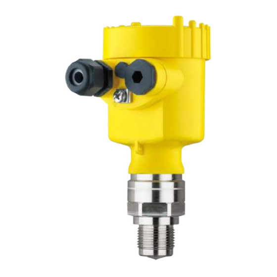
Vega VEGAPULS 6X Operating Instructions Manual
Radar sensor for continuous level measurement of liquids and bulk solids
Hide thumbs
Also See for VEGAPULS 6X:
- Operating instructions manual (164 pages) ,
- Quick setup manual (36 pages) ,
- Safety instruction (16 pages)

Subscribe to Our Youtube Channel
Related Manuals for Vega VEGAPULS 6X


Summary of Contents for Vega VEGAPULS 6X
- Page 1 Operating Instructions Radar sensor for continuous level measurement of liquids and bulk solids VEGAPULS 6X PROFINET, Modbus TCP, OPC UA (Ether- net-APL) Document ID: 1034189...
-
Page 2: Table Of Contents
Set up with the display and adjustment module ..............53 Insert display and adjustment module ................53 Adjustment system ......................53 Measured value indication - Selection of national language ........... 54 Parameter adjustment ....................55 VEGAPULS 6X • PROFINET, Modbus TCP, OPC UA (Ethernet-APL) - Page 3 17.8 How to proceed if a repair is necessary ................ 114 18 Dismount..........................115 18.1 Dismounting steps......................115 18.2 Disposal ........................115 19 Certificates, approvals and certifications ................. 116 19.1 Radio licenses ......................116 19.2 Approvals for Ex areas ....................116 VEGAPULS 6X • PROFINET, Modbus TCP, OPC UA (Ethernet-APL)
- Page 4 20.2 Radio astronomy stations ..................... 140 20.3 Dimensions ........................140 20.4 Industrial property rights ....................158 20.5 Licensing information for open source software ............158 20.6 Trademark ........................158 Editing status: 2024-01-29 VEGAPULS 6X • PROFINET, Modbus TCP, OPC UA (Ethernet-APL)
-
Page 5: About This Document
Symbols used Document ID This symbol on the front page of this instruction refers to the Docu- ment ID. By entering the Document ID on www.vega.com you will reach the document download. Information, note, tip: This symbol indicates helpful additional infor- mation and tips for successful work. -
Page 6: For Your Safety
During work on and with the device, the required personal protective equipment must always be worn. Appropriate use VEGAPULS 6X is a sensor for continuous level measurement. You can find detailed information about the area of application in chapter "Product description". Operational reliability is ensured only if the instrument is properly used according to the specifications in this document as well as pos- sible supplementary instructions. -
Page 7: Mode Of Operation - Radar Signal
Installations in Canada shall comply with the relevant requirements of the Canadian Electrical Code (CEC Part I) (Canada). A Class 2 power supply unit has to be used for the installation in the USA and Canada. VEGAPULS 6X • PROFINET, Modbus TCP, OPC UA (Ethernet-APL) -
Page 8: Product Description
– If necessary, further certificates Information: Optional instrument features are also described in this instructions manual. The respective scope of delivery results from the order specification. Use see chapter "Mounting instructions, sealing to the process" VEGAPULS 6X • PROFINET, Modbus TCP, OPC UA (Ethernet-APL) -
Page 9: Principle Of Operation
• Open the VEGA Tools app and enter the serial number under "Documentation". Principle of operation Application area The VEGAPULS 6X is a radar sensor for continuous level measure- ment of liquids as well as bulk solids under different process condi- tions. Antenna systems The instrument is available with different antenna systems: VEGAPULS 6X • PROFINET, Modbus TCP, OPC UA (Ethernet-APL) -
Page 10: Adjustment
Wireless adjustment Devices with integrated Bluetooth module can be adjusted wirelessly via standard adjustment tools: • Smartphone/tablet (iOS or Android operating system) • PC/notebook (Windows operating system) VEGAPULS 6X • PROFINET, Modbus TCP, OPC UA (Ethernet-APL) - Page 11 Smartphone/Tablet PC/Notebook Adjustment via the signal Devices can be operated in the following ways via the connected cable Ethernet APL cable: • Ethernet APL network with instrument master file (GSD) • Integrated webserver • PC adjustment tool DTM/PACTware VEGAPULS 6X • PROFINET, Modbus TCP, OPC UA (Ethernet-APL)
-
Page 12: Packaging, Transport And Storage
ISO 4180. The packaging consists of environment-friendly, recyclable card- board. For special versions, PE foam or PE foil is also used. Dispose of the packaging material via specialised recycling companies. VEGAPULS 6X • PROFINET, Modbus TCP, OPC UA (Ethernet-APL) -
Page 13: Accessories
VEGACONNECT The interface adapter VEGACONNECT enables the connection of communication-capable instruments to the USB interface of a PC. VEGADIS 81 The VEGADIS 81 is an external display and adjustment unit for VEGA plics sensors. ® Welded socket, threaded Welded sockets are used to connect the devices to the process. -
Page 14: Setup - The Most Important Steps
Parameterize sensor Liquids Bulk solids Enter medium type, application, vessel height, adjustment and mode 100% 100% Check measured value Indicators Output Download via Apple App Store, Google Play Store, Baidu Store VEGAPULS 6X • PROFINET, Modbus TCP, OPC UA (Ethernet-APL) -
Page 15: Mounting
• Abrasion and mechanical influences Second Line of Defense As a standard feature, the VEGAPULS 6X is separate from the pro- cess through its plastic antenna encapsulation. Optionally, the instrument is available with a Second Line of Defense (SLOD), a second process separation. It is located as gas-tight leadthrough between the process component and the electronics. - Page 16 For devices in protection class IP66/IP68 (1 bar), ventilation is pro- vided by a capillary in the fixed cable. In these devices, a blind plug is installed in the housing instead of the filter element. The housing of VEGAPULS 6X can be rotated completely by 360°. Housing orientation This enables optimal reading of the display and easy cable entry. For housings made of plastic or electropolished stainless steel, this is done without tools.
- Page 17 2. Unscrew the locking screw from the cover up to the stop using a size 4 hexagonal spanner 3. Check if the cover can no longer be turned The housing cover is unlocked in the opposite way. VEGAPULS 6X • PROFINET, Modbus TCP, OPC UA (Ethernet-APL)
-
Page 18: Mounting Preparations, Mounting Strap
Single chamber housing – Inclination in three steps 0°, 90° and 180° – Inclination 180° steplessly • Double chamber housing – Inclination in two steps 0° and 90° – Inclination 90° steplessly VEGAPULS 6X • PROFINET, Modbus TCP, OPC UA (Ethernet-APL) -
Page 19: Mounting Versions, Plastic Horn Antenna
Mounting strap - Ceiling The instrument is normally mounted vertically with a bracket on the mounting ceiling. This allows swivelling the sensor up to 180° for optimal orientation and rotating for optimal connection. VEGAPULS 6X • PROFINET, Modbus TCP, OPC UA (Ethernet-APL) - Page 20 Fig. 12: Wall mounting horizontally via the mounting strap with length 170 mm Fig. 13: Wall mounting with inclined wall via the mounting strap with length 300 mm Flange Two versions are available for mounting the instrument on a nozzle: VEGAPULS 6X • PROFINET, Modbus TCP, OPC UA (Ethernet-APL)
-
Page 21: Mounting Instructions
Fig. 15: Adapter flange Connection screw 2 Adapter flange Process seal Mounting instructions Radar sensors for level measurement emit electromagnetic waves. Polarisation The polarisation is the direction of the electrical share of these waves. It is identifiable by a mark on the housing, see the following drawing: VEGAPULS 6X • PROFINET, Modbus TCP, OPC UA (Ethernet-APL) - Page 22 (7.874 in) from the vessel wall. If the device is installed in the center of dished or round vessel tops, multiple echoes can arise. However, these can be suppressed by an appropriate adjustment (see chapter "Setup"). VEGAPULS 6X • PROFINET, Modbus TCP, OPC UA (Ethernet-APL)
- Page 23 Mount the instrument at least 200 mm (7.874 in) away from the vessel solids wall. In this case, it is recommended to repeat the false signal suppression at a later time with existing buildup. VEGAPULS 6X • PROFINET, Modbus TCP, OPC UA (Ethernet-APL)
- Page 24 This applies especially if buildup on the vessel wall is to be expected. Reference plane The measuring range of the VEGAPULS 6X physically begins with the antenna end. However, the min./max. adjustment begins mathematically with the reference plane, which is located differently depending on the sensor version.
- Page 25 5 Hygienic fitting Horn antenna Flange with lens antenna Inflowing medium - liq- Do not mount the instrument in or above the filling stream. Make sure uids that you detect the medium surface, not the inflowing product. Fig. 21: Mounting of the radar sensor with inflowing medium Inflowing medium - bulk As a general rule, the device must not be mounted too close to or solids above the inflowing medium, otherwise the radar signal could be disturbed. VEGAPULS 6X • PROFINET, Modbus TCP, OPC UA (Ethernet-APL)
- Page 26 5 Mounting Silo with filling from top: The optimal mounting position is opposite the filling aperture. To avoid heavy soiling of the antenna, the distance to any filter or dust exhauster should be as large as possible. Fig. 22: Mounting of the radar sensor with inflowing medium – filling from top Silo with lateral filling: The optimal mounting position is next to the filling. To avoid heavy soiling of the antenna, the distance to any filter or dust exhauster should be as large as possible. VEGAPULS 6X • PROFINET, Modbus TCP, OPC UA (Ethernet-APL)
- Page 27 For nozzle mounting, the nozzle should be as short as possible and Socket mounting - short nozzles its end rounded. This reduces false reflections from the nozzle. With threaded connection, the antenna end should protrude at least 5 mm (0.2 in) out of the nozzle. VEGAPULS 6X • PROFINET, Modbus TCP, OPC UA (Ethernet-APL)
- Page 28 Flange with lens antenna Socket mounting - longer If the reflective properties of the medium are good, you can mount nozzles VEGAPULS 6X on sockets longer than the antenna. The socket end should be smooth and burr-free, if possible also rounded. Note: When mounting on a longer socket piece, we recommend to carry out a false signal suppression (see chapter "Parameter adjustment").
- Page 29 Socket diameter "d" Socket length "h" 40 mm 1½" ≤ 150 mm ≤ 5.9 in 50 mm 2" ≤ 200 mm ≤ 7.9 in 80 mm 3" ≤ 300 mm ≤ 11.8 in 100 mm 4" ≤ 400 mm ≤ 15.8 in 150 mm 6" ≤ 600 mm ≤ 23.6 in VEGAPULS 6X • PROFINET, Modbus TCP, OPC UA (Ethernet-APL)
- Page 30 Antenna encapsulation Note: PTFE-plated flanges, however, have a preload loss over time with large temperature changes. This can negatively the sealing proper- ties. To avoid this, use the disc springs from the scope of delivery during mounting. They fit the required flange screws. Proceed as follows to seal effectively: 1. Use flange screws according to the number of flange holes VEGAPULS 6X • PROFINET, Modbus TCP, OPC UA (Ethernet-APL)
- Page 31 G1½ G1½ SW 65 SW 60 (2.56") (2.36") G1½A Fig. 28: VEGAPULS 6X with PTFE threaded adapter (example VEGAPULS 6X with thread G1½) Sensor O-ring seal (sensor side) PTFE threaded adapter Flat seal (process side) Welded socket VEGAPULS 6X • PROFINET, Modbus TCP, OPC UA (Ethernet-APL)
- Page 32 Fig. 29: Mounting the instrument on insulated vessels Vessel insulation Distance piece for temperature decoupling Electronics housing Vessel installations The mounting location of the radar sensor should be a place where no other equipment or fixtures cross the path of the radar signals. VEGAPULS 6X • PROFINET, Modbus TCP, OPC UA (Ethernet-APL)
- Page 33 Orientation - Bulk solids In a cylindrical silo with conical outlet, the mounting is carried out on a third up to the half of the vessel radius from outside (see following drawing). VEGAPULS 6X • PROFINET, Modbus TCP, OPC UA (Ethernet-APL)
- Page 34 It depends on the measuring distance "d" and the distance "a" between vessel centre and mounting position. Check the alignment with a suitable level or water level. VEGAPULS 6X • PROFINET, Modbus TCP, OPC UA (Ethernet-APL)
- Page 35 5 Mounting Fig. 33: Determination of the angle of inclination for alignment of VEGAPULS 6X Distance d (m) 2° 4° 6° 8° 10° 10.5 12.2 11.1 13.9 12.5 15.6 10.5 13.9 17.4 VEGAPULS 6X • PROFINET, Modbus TCP, OPC UA (Ethernet-APL)
- Page 36 3. Re-tighten the terminal screws, max. torque see chapter "Techni- cal data". Agitators Agitators in the vessel can reflect the measurement signal and thus lead to undesired incorrect measurements. Note: To avoid this, a false signal suppression should be carried out with the agitators in motion. This ensures that the interfering reflections from the agitators are saved with the blades in different positions. VEGAPULS 6X • PROFINET, Modbus TCP, OPC UA (Ethernet-APL)
- Page 37 In these applications, it must be taken into account that the radar sen- sors are designed for relatively slow level changes. Therefore, when using on moving parts, observe the measurement characteristics of the device (see chapter "Technical data"). VEGAPULS 6X • PROFINET, Modbus TCP, OPC UA (Ethernet-APL)
- Page 38 The sensor should be directed towards the emptying point in the centre of the silo. This can be done, for example, using the mount- ing strap. Fig. 37: Installation and orientation in multiple chamber silos VEGAPULS 6X • PROFINET, Modbus TCP, OPC UA (Ethernet-APL)
- Page 39 To protect the device against buildup, particularly in case of strong condensation, air rinsing is recommended. Plastic horn antenna: The VEGAPULS 6X with plastic horn antenna is optionally available with a rinsing air connection. The mechanical configuration differs according to the flange version, see following graphics. Fig. 39: Plastic horn antenna with compression flange Rinsing air connection VEGAPULS 6X •...
-
Page 40: Measuring Rigs - Bypass
The VEGAPULS 6X in 80 GHz technology is suitable as standard for non-contact level measurement in such a bypass. VEGAPULS 6X • PROFINET, Modbus TCP, OPC UA (Ethernet-APL) - Page 41 For stand pipe lengths > 3 m, the antenna diameter must be cho- sen as large as possible, but at least 80 mm/3" • A false signal suppression with the installed sensor is recom- mended but not mandatory VEGAPULS 6X • PROFINET, Modbus TCP, OPC UA (Ethernet-APL)
-
Page 42: Measurement Setup - Flow
• Rectangular weir broad crown (ISO 3846) Flow formula: If the flow formula of your flume is known, you should select this op- tion, as the accuracy of the flow measurement is highest here. The value given takes into account the block distance. At smaller distances, the measuring accuracy is reduced, see "Technical data". VEGAPULS 6X • PROFINET, Modbus TCP, OPC UA (Ethernet-APL) - Page 43 Detailed project planning data can be found at the channel manufac- turers and in the technical literature. The following examples serve as an overview for flow measurement. Rectangular overfall 3 ... 4 h 90° 90° Fig. 43: Flow measurement with rectangular flume: h = max. filling of the max. rectangular flume 1 Overfall orifice (side view) Upstream water Tailwater 4 Overfall orifice (view from tailwater) VEGAPULS 6X • PROFINET, Modbus TCP, OPC UA (Ethernet-APL)
- Page 44 5 Mounting Khafagi-Venturi flume 3 ... 4 x h 90° Fig. 44: Flow measurement with Khafagi-Venturi flume: h = max. filling of the max. flume; B = tightest constriction in the flume Position sensor 2 Venturi flume VEGAPULS 6X • PROFINET, Modbus TCP, OPC UA (Ethernet-APL)
-
Page 45: Connecting To Power Supply
In the case of instrument housings with self-sealing NPT threads, it is not possible to have the cable entries screwed in at the factory. The free openings for the cable glands are therefore covered with red dust protection caps as transport protection. VEGAPULS 6X • PROFINET, Modbus TCP, OPC UA (Ethernet-APL) -
Page 46: Connecting
Fig. 45: Connection steps 5 and 6 6. Insert the wire ends into the terminals according to the wiring plan Note: Fixed conductors and flexible conductors with ferrules can be inserted directly into the terminal openings. In the case of flexible conductors for opening the terminals, use a screwdriver (3 mm blade VEGAPULS 6X • PROFINET, Modbus TCP, OPC UA (Ethernet-APL) -
Page 47: Wiring Plan
Ground terminal for connection of the cable screening APL status LEDs Function Link Lights green: Connection established Flashes green: RX/TX activity Status Device status according to NE 107) Flashes orange: "Discovery Configuration Protocol" activated with "Service Identify" VEGAPULS 6X • PROFINET, Modbus TCP, OPC UA (Ethernet-APL) -
Page 48: Wiring Plan - Version Ip66/Ip68 (1 Bar)
After connection to the power supply, the device carries out a self- test: • Internal check of the electronics • Status LED lights red • Output signal is set to failure The current measured value is then output on the signal cable. VEGAPULS 6X • PROFINET, Modbus TCP, OPC UA (Ethernet-APL) -
Page 49: Access Protection, It Security
(SHA 256 algorithm). Protection of the parameterization The settings (parameters) of the device can be protected against un- wanted changes. The parameter protection is deactivated on delivery, all settings can be made. VEGAPULS 6X • PROFINET, Modbus TCP, OPC UA (Ethernet-APL) -
Page 50: Storing The Codes In Myvega
"PINs and Codes". This greatly simplifies the use of additional adjust- ment tools, as all Bluetooth access and device codes are automati- cally synchronized when connected to the "myVEGA" account VEGAPULS 6X • PROFINET, Modbus TCP, OPC UA (Ethernet-APL) -
Page 51: Set Up With Web Server
The sensor adjustment menu is divided into three section: • Header with status and current measured values • Navigation section • Menu item display The selected menu item is indicated by the colour change in the navigation area. VEGAPULS 6X • PROFINET, Modbus TCP, OPC UA (Ethernet-APL) - Page 52 Fig. 48: Example of an adjustment menu view - Start page Enter the desired parameters. Press the "Accept" button to transfer the entries to the sensor. The entries are now active in the sensor. Close the browser to terminate connection. VEGAPULS 6X • PROFINET, Modbus TCP, OPC UA (Ethernet-APL)
-
Page 53: Set Up With The Display And Adjustment Module
– Confirm selected menu – Edit parameter – Save value • [->] key: – Change measured value presentation – Select list entry – Select menu items – Select editing position • [+] key: VEGAPULS 6X • PROFINET, Modbus TCP, OPC UA (Ethernet-APL) -
Page 54: Measured Value Indication - Selection Of National Language
Approx. 60 minutes after the last pressing of a key, an automatic reset to measured value indication is triggered. Any values not confirmed with [OK] will not be saved. Measured value indication - Selection of national language Measured value indica- With the [->] key you move between three different indication modes: tion VEGAPULS 6X • PROFINET, Modbus TCP, OPC UA (Ethernet-APL) -
Page 55: Parameter Adjustment
Here you can assign a suitable measurement loop name. You can enter names with max. 19 characters. The character set comprises: • Capital letters from A … Z • Numbers from 0 … 9 VEGAPULS 6X • PROFINET, Modbus TCP, OPC UA (Ethernet-APL) - Page 56 Multiple reflections through dished ves- spirals sel ceiling Nozzle Condensation, buildup on the sensor Dosing vessel Small vessels Frequent and fast filling/emptying Tight installation situation Multiple reflections through dished ves- sel ceiling Product buildup, condensate and foam gen- eration VEGAPULS 6X • PROFINET, Modbus TCP, OPC UA (Ethernet-APL)
- Page 57 Slow gauge change flume/Overfall Smooth to agitated water surface Measurement often from a short distance with the demand for accurate measure- ment results Ice and condensation on the antenna pos- sible VEGAPULS 6X • PROFINET, Modbus TCP, OPC UA (Ethernet-APL)
- Page 58 Large volume Large distance to the medium False signal sup- pression Steep angles of repose, unfavourable pour- ing positions due to outlet funnel and filling cone Diffuse reflections due to structured vessel walls or internals Multiple echoes/diffuse reflections due to unfavourable pouring positions with fine grain Changing signal conditions when large amounts of material slip off VEGAPULS 6X • PROFINET, Modbus TCP, OPC UA (Ethernet-APL)
- Page 59 (min./max. adjustment). During adjustment, enter the respective measuring distance when the vessel is full and empty (see the following examples): VEGAPULS 6X • PROFINET, Modbus TCP, OPC UA (Ethernet-APL)
- Page 60 Max. level = min. meas. distance (distance A) Reference plane If these values are not known, and adjustment can for example be carried out with the distances of 10 % and 90 %. The starting point for these distance specifications is always the refer- ence plane, e.g. the sealing surface of the thread or flange. Informa- VEGAPULS 6X • PROFINET, Modbus TCP, OPC UA (Ethernet-APL)
- Page 61 9.4.3 Access protection Bluetooth access code This menu item enables to change the factory-preset Bluetooth ac- cess code to your personal Bluetooth access code. VEGAPULS 6X • PROFINET, Modbus TCP, OPC UA (Ethernet-APL)
- Page 62 During a reset, parameter settings made by the user are reset to the values of the factory settings. You can fined the values in chapter "Menu overview". Information: The language and Bluetooth access code are not reset, a currently running simulation however is aborted. VEGAPULS 6X • PROFINET, Modbus TCP, OPC UA (Ethernet-APL)
- Page 63 Corresponding linearisation curves are stored for these measurement situations. They indicate the relationship between the percentage level and the vessel volume or flow rate. The selection depends on the selected linerarisation type liquid or bulk solid. The event and parameter change memories are maintained. VEGAPULS 6X • PROFINET, Modbus TCP, OPC UA (Ethernet-APL)
- Page 64 Display - Presentation With the [->] key you move between three different indication modes: • Measured value in large font • Measured value and corresponding bargraph presentation • Measured value as well as second selectable value, e.g. electron- ics temperature VEGAPULS 6X • PROFINET, Modbus TCP, OPC UA (Ethernet-APL)
- Page 65 1. Select with [->] the menu item "False signal suppression" and confirm with [OK]. 2. Confirm 2-times with [OK] and enter the actual distance from the sensor to the product surface. 3. All interfering signals in this range are detected by the sensor and stored after being confirmed with [OK]. VEGAPULS 6X • PROFINET, Modbus TCP, OPC UA (Ethernet-APL)
- Page 66 Herzegovina, Canada, Liechtenstein, Moldavia, Monaco, Montenegro, New Zealand, Northern Macedonia, Norway, San Marino, Saudi Arabia, Serbia, Switzerland, Turkey, Ukraine, United Kingdom, USA • Mode of operation 2: Brazil, Japan, South Korea, Taiwan, Thailand VEGAPULS 6X • PROFINET, Modbus TCP, OPC UA (Ethernet-APL)
- Page 67 If the data do not match, a fault message is outputted or the function is blocked. The data are saved only after release. VEGAPULS 6X • PROFINET, Modbus TCP, OPC UA (Ethernet-APL)
- Page 68 The following min./max. values saved by the sensor are displayed in indicator the menu item "Measured values/Peak indicator": • Distance • Measurement reliability • Measuring rate • Electronics temperature • Operating voltage VEGAPULS 6X • PROFINET, Modbus TCP, OPC UA (Ethernet-APL)
- Page 69 In this menu item you can simulate measured values. This allows the signal path to be tested, e.g. through downstream indicating instru- ments or the input card of the control system. VEGAPULS 6X • PROFINET, Modbus TCP, OPC UA (Ethernet-APL)
- Page 70 SP01 - Activate measur- Measuring range start limiting is activated here. The appropriate ing range start limiting distance value is set in the special parameter SP02. → Jumps in the measured value to a changing false signal in the close range can thus be prevented. VEGAPULS 6X • PROFINET, Modbus TCP, OPC UA (Ethernet-APL)
- Page 71 SP07 - Deactivate filter This parameter is always switched on ex-factory. It acts as a digital function "Smooth raw filter over the raw value curve depending on the selected application. value curve" → In principle, it causes an improvement in measurement reliability. Note: Therefore, switching off only makes sense in very special applications that need to be clarified. VEGAPULS 6X • PROFINET, Modbus TCP, OPC UA (Ethernet-APL)
- Page 72 This parameter in "m" entered here determines how great the dis- for "Summarize echoes" tance between the end of the first echo and the start of the second function echo may be at the maximum in order for them to be summarized. SP15 - Activate "First When this parameter is activated, the first echo not saved as a false large echo" function echo with sufficiently great amplitude is selected as a product echo. VEGAPULS 6X • PROFINET, Modbus TCP, OPC UA (Ethernet-APL)
- Page 73 This value in "%" is additional safety below the 0 % adjustment related ditional reliability at the to the measuring range. measuring range end → It supports the detection of an echo when the vessel is completely empty, even with unfavourable vessel bottom shapes. VEGAPULS 6X • PROFINET, Modbus TCP, OPC UA (Ethernet-APL)
-
Page 74: Save Parameter Adjustment Data
If the instrument is equipped with a display and adjustment module, ment module the parameter adjustment data can be saved therein. The procedure is described in menu item "Copy device settings". VEGAPULS 6X • PROFINET, Modbus TCP, OPC UA (Ethernet-APL) -
Page 75: Set Up With Smartphone/Tablet
Operating system: Android 5.1 or newer • Bluetooth 4.0 LE or newer Download the VEGA Tools app from the "Apple App Store", "Goog- le Play Store" or "Baidu Store" to your smartphone or tablet. Make sure that the Bluetooth function of the display and adjustment module is activated. -
Page 76: Parameter Adjustment
• Navigation section • Menu item display The selected menu item can be recognized by the colour change. VEGAPULS 6X • PROFINET, Modbus TCP, OPC UA (Ethernet-APL) - Page 77 10 Set up with Smartphone/tablet Fig. 55: Example of an app view - Setup measured values Enter the requested parameters and confirm via the keyboard or the editing field. The settings are then active in the sensor. Close the app to terminate connection. VEGAPULS 6X • PROFINET, Modbus TCP, OPC UA (Ethernet-APL)
-
Page 78: Set Up With Pc/Notebook
Bluetooth 4.0 LE or newer Make sure that the Bluetooth function of the display and adjustment module is activated. For this, the switch on the bottom side must be set to "On". VEGAPULS 6X • PROFINET, Modbus TCP, OPC UA (Ethernet-APL) -
Page 79: Connecting (Bluetooth)
Authenticate When establishing the connection for the first time, the operating tool and the device must authenticate each other. After the first correct authentication, each subsequent connection is made without a new authentication query. Enter Bluetooth access For authentication, enter in the next menu window the 6-digit code Bluetooth access code: VEGAPULS 6X • PROFINET, Modbus TCP, OPC UA (Ethernet-APL) - Page 80 It is recommended to enter a personal 6-digit device code. To do this, go to menu "Extended functions", "Access protection", menu item "Protection of the parameter adjustment". VEGAPULS 6X • PROFINET, Modbus TCP, OPC UA (Ethernet-APL)
-
Page 81: Connect The Pc (Vegaconnect)
"DTM Collection/PACTware" attached to each DTM Collection and which can also be downloaded from the Internet. Detailed descrip- tions are available in the online help of PACTware and the DTMs. VEGAPULS 6X • PROFINET, Modbus TCP, OPC UA (Ethernet-APL) -
Page 82: Save Parameter Adjustment Data
Fig. 59: Example of a DTM view 11.6 Save parameter adjustment data We recommend documenting or saving the parameterisation data via PACTware. That way the data are available for multiple use or service purposes. VEGAPULS 6X • PROFINET, Modbus TCP, OPC UA (Ethernet-APL) -
Page 83: Menu Overview
0,000 m Distance B (min. Min. value Min. adjustment value) 0 % corresponds to 120,000 m Plastic horn antenna, thread with integrated antenna system, flange with encapsulated antenna system Flange with lens antenna Plastic horn antenna, thread with integrated antenna system, flange with encapsulated antenna system Flange with lens antenna VEGAPULS 6X • PROFINET, Modbus TCP, OPC UA (Ethernet-APL) - Page 84 Displayed values 1, 2 Percent, linearized percent, filling height, Percent distance, scaled, measurement reliability, electronics temperature, current output, cur- rent output 2 Backlight On, Off False signal sup- False signal sup- Create new, expand, delete all pression pression VEGAPULS 6X • PROFINET, Modbus TCP, OPC UA (Ethernet-APL)
- Page 85 Reset to factory settings, Restart Diagnostics Menu item Parameter Selection/Display Default setting Diagnosis status Diagnosis status Diagnosis status Change counter Checksum (CRC) Date parameter adjustment APL-Link-Quality Echo curve Echo curve Indication of echo curve VEGAPULS 6X • PROFINET, Modbus TCP, OPC UA (Ethernet-APL)
- Page 86 2 Device memory Echo curve of the Save echo curve of setup setup Echo curve memory Echo curve memory VEGAPULS 6X • PROFINET, Modbus TCP, OPC UA (Ethernet-APL)
-
Page 87: Special Parameters
"Summarize echoes" function SP14 Echo distance for "Summa- 0.500 m rize echoes" function SP15 Activate function measure- Deactivated ment of the "first large echo" SP16 Minimum amplitude function 12 dB "First large echo" VEGAPULS 6X • PROFINET, Modbus TCP, OPC UA (Ethernet-APL) - Page 88 Minimum measurement relia- 6 dB bility outside focussing range SP19 Time for opening the focus- sing range SP22 Measured value offset 0.000 m SP24 Factor for additional reliability 0.0 % at measuring range end VEGAPULS 6X • PROFINET, Modbus TCP, OPC UA (Ethernet-APL)
-
Page 89: Profinet System Integration
13 PROFINET system integration 13.1 Instrument master file (GSD) For the configuration of a PROFINET controller (e.g. Siemens SPS) you require the manufacturer-specific PROFINET device master file (GSD file) of VEGAPULS 6X or the Profil-GSD file for LEVEL_RA- DAR. VEGA GSD file The manufacturer-specific GSD file can be downloaded directly from the VEGAPULS 6X using the integrated web server or via our download area. File name (example): GSDML-V2.43-VEGA-VE- GAPULS6X-20231220.xml Manufacturer ID (VEGA): 0x0062 (=98) Device ID (VEGAPULS 6X): 0x4754 (=18260) Profil-GSD file The Profil-GSD file for the "PROFINET PA Profile LEVEL_RADAR" can be downloaded directly from the PROFINET-International (PI) website if it is not pre-installed in the controller. -
Page 90: Device Identification With Dcp
Measurement Rate √ Measuring rate Operating Voltage √ Operating voltage APL SNR √ APL signal-to- noise-ratio AnalogInput The measured values in the module "AnalogInput" each consist of five bytes; in the first four bytes, the measured value is transmitted as a floating point number in the IEEE 754 standard. The fifth byte contains the corresponding status. VEGAPULS 6X • PROFINET, Modbus TCP, OPC UA (Ethernet-APL) -
Page 91: I&M Data
I&M data stands for "Identification & Maintenance data". This data can be read or written from the sensor using acyclic data exchange and helps to identify and maintain devices in a PROFINET network. The VEGAPULS 6X supports the data "I&M 0 … 3" acc. to the pro- file 4.02 "Profile for Process Control Devices". Main function... -
Page 92: Startup Parameter
Note: The VEGAPULS 6X supports the PROFINET system redundanc S2, there are no additional settings in the sensor necessary. VEGAPULS 6X • PROFINET, Modbus TCP, OPC UA (Ethernet-APL) -
Page 93: Modbus Tcp
Modbus messages. This means that Modbus data is embedded in TCP packets and sent via IP networks. A Modbus TCP server is inte- grated in the VEGAPULS 6X, whose data can be read and accessed with a Modbus TCP host (e.g. PLC). -
Page 94: Input Register
Profibus Unit Codes Status Level VEGA-State Distance Value 114, 115 IEEE 754 Format Unit Distance Profibus Unit Codes Status Distance VEGA-State Scaled Value 118, 119 IEEE 754 Format Unit Scaled Profibus Unit Codes Status Scaled VEGA-State Percent VEGAPULS 6X • PROFINET, Modbus TCP, OPC UA (Ethernet-APL) - Page 95 Status Measurement rate VEGA-State Operating voltage Value 142, 143 IEEE 754 Format Unit Operating voltage Profibus Unit Codes Status Operating voltage VEGA-State APL-SNR Value 146, 147 IEEE 754 Format Unit APL-SNR Profibus Unit Codes Status APL-SNR VEGA-State VEGAPULS 6X • PROFINET, Modbus TCP, OPC UA (Ethernet-APL)
-
Page 96: Opc Ua
Device Hardware version Manufacturer „VEGA Grieshaber KG“ Model Device Name ProductCode Device Ordernumber SerialNumber Device Serialnumber SoftwareRevision Device Software version URI of Manufacturer „http://www.vega.com“ URI of Product instance Link to VEGA Serialnumbersearch VEGAPULS 6X • PROFINET, Modbus TCP, OPC UA (Ethernet-APL) -
Page 97: Date/Time
2 can be set in the menu "Extended settings" - "SNTP" menu. Note: The SNTP client must be activated for the device (menu item "Ex- tended settings" - "Network services"). VEGAPULS 6X • PROFINET, Modbus TCP, OPC UA (Ethernet-APL) -
Page 98: Diagnosis, Asset Management And Service
3 minutes. The requested values and recording conditions are set via a PC with PACTware/DTM or the control system with EDD. Data are thus read out and also reset. VEGAPULS 6X • PROFINET, Modbus TCP, OPC UA (Ethernet-APL) -
Page 99: Asset Management Function
"Diagnostics" via the respective adjustment module. Status messages The status messages are divided into the following categories: • Failure • Function check • Out of specification • Maintenance required and explained by pictographs: VEGAPULS 6X • PROFINET, Modbus TCP, OPC UA (Ethernet-APL) - Page 100 Values are not con- Check linearization table Byte 5, Bit 2 of Byte 0 … 5 tinuously rising, for Error in the lineari- Delete table/Create new example illogical zation table value pairs VEGAPULS 6X • PROFINET, Modbus TCP, OPC UA (Ethernet-APL)
- Page 101 Check operating voltage Byte 4, Bit 3 of Byte 0 … 5 carries out a meas- Measurement func- Carry out a reset urement tion disturbed Disconnect operating voltage Operating voltage briefly too low VEGAPULS 6X • PROFINET, Modbus TCP, OPC UA (Ethernet-APL)
- Page 102 Level echo in the close range not Reduce level Byte 23, Bit 1 of available Byte 14 … 24 Overfilling 100 % adjustment: Increase value Check mounting socket Remove possible interfering sig- nals in the close range VEGAPULS 6X • PROFINET, Modbus TCP, OPC UA (Ethernet-APL)
-
Page 103: Echo Curve
The echo curve enables a detailed assessment of the characteristics of a level measurement with the VEGAPULS 6X. The following chapters show the basic course of the echo curve and describe the menu functions. VEGAPULS 6X • PROFINET, Modbus TCP, OPC UA (Ethernet-APL) - Page 104 10 False signal suppression 11 Detected echo with initial and end point 12 Echo data of the selected echo 13 Echo curve of the setup 14 Useful echo history 15 Echo curve unfiltered VEGAPULS 6X • PROFINET, Modbus TCP, OPC UA (Ethernet-APL)
- Page 105 A high-resolution echo curve stored by the user during setup. Echo curve of the setup → It can be used to detect signal changes over the operating time. High resolution The maximum number of scanning points available in the sensor is displayed. → The high-resolution display of the echo curve is necessary for a meaningful assessment of the echo curve. VEGAPULS 6X • PROFINET, Modbus TCP, OPC UA (Ethernet-APL)
- Page 106 Clicking with left mouse button on echo pro- vides indication of associated echo data Detection curve False signal suppression Echo curve unfiltered Is only visible in the service login and Useful echo history VEGAPULS 6X • PROFINET, Modbus TCP, OPC UA (Ethernet-APL)
- Page 107 By shifting the mouse, the displayed presentation ar- ea is shifted as well. Note: The DTM version, the measuring principle and the device version of the recordings must match the current DTM VEGAPULS 6X • PROFINET, Modbus TCP, OPC UA (Ethernet-APL)
- Page 108 Ident number assigned by the sensor to the detect- ed echo Location Distance from the sensor reference plane to the echo Amplitude Echo amplitude of the re- spective echo in dB VEGAPULS 6X • PROFINET, Modbus TCP, OPC UA (Ethernet-APL)
-
Page 109: Rectify Faults
The images in column "Error pattern" show the real level as a broken line and the level displayed by the sensor as a continuous line. time Fig. 65: Display of error images Real level Level displayed by the sensor VEGAPULS 6X • PROFINET, Modbus TCP, OPC UA (Ethernet-APL) - Page 110 Max. adjustment not correct Remove contamination on the antenna In case of interferences due to installations in the close range: Change polarisation di- rection time Create a new false signal suppression Adapt max. adjustment VEGAPULS 6X • PROFINET, Modbus TCP, OPC UA (Ethernet-APL)
- Page 111 Carry out a false signal suppression or jumps sporadically to the antenna. increase false signal suppression with con- 100 % during filling densation/contamination in the close range by editing. With bulk solids, use radar sensor with purging air connection. time VEGAPULS 6X • PROFINET, Modbus TCP, OPC UA (Ethernet-APL)
- Page 112 24 hour service hotline Should these measures not be successful, please call in urgent cases the VEGA service hotline under the phone no. +49 1805 858550. The hotline is also available outside normal working hours, seven days a week around the clock.
-
Page 113: Exchanging The Electronics Module
You can find information about the installation in the download file. Caution: Instruments with approvals can be bound to certain software versions. Therefore make sure that the approval is still effective after a software update is carried out. You can find detailed information in the download area at www.vega.com. VEGAPULS 6X • PROFINET, Modbus TCP, OPC UA (Ethernet-APL) -
Page 114: How To Proceed If A Repair Is Necessary
Print the generated instrument return form. Clean the instrument and pack it damage-proof. Send the printed instrument return form and possibly a safety data sheet together with the device. You will find the address for the return on the generated instrument return form. VEGAPULS 6X • PROFINET, Modbus TCP, OPC UA (Ethernet-APL) -
Page 115: Dismount
If personal data is stored on the old device to be disposed of, delete it before disposal. If you have no way to dispose of the old instrument properly, please contact us concerning return and disposal. VEGAPULS 6X • PROFINET, Modbus TCP, OPC UA (Ethernet-APL) -
Page 116: Certificates, Approvals And Certifications
NE 43 – Signal level for fault information from measuring transduc- • NE 53 – Compatibility of field devices and display/adjustment components • NE 107 – Self-monitoring and diagnosis of field devices For further information see www.namur.de. 19.6 IT Security The device is available as version with IT security acc. to IEC 62443- 4-2 or in preparation. VEGAPULS 6X • PROFINET, Modbus TCP, OPC UA (Ethernet-APL) -
Page 117: Material And Test Cerfificates
DIN EN ISO 14001. Help us to meet these requirements and observe the environmental instructions in the chapters "Packaging, transport and storage", "Dis- posal" of this instructions manual. VEGAPULS 6X • PROFINET, Modbus TCP, OPC UA (Ethernet-APL) -
Page 118: Supplement
Ʋ Surface roughness metallic adapter < 0.76 µm Ʋ Additional process seal depending on FKM (PPE V70SW), FFKM (Kalrez 6230, Perlast G74S), the hygienic fitting EPDM (Freudenberg 291) Flange with lens antenna Ʋ Process fitting 316L Ʋ Antenna PEEK VEGAPULS 6X • PROFINET, Modbus TCP, OPC UA (Ethernet-APL) - Page 119 Ʋ G¾ 30 Nm (22.13 lbf ft) Ʋ G1½ 200 Nm (147.5 lbf ft) Ʋ G1½ (with PTFE threaded adapter) 5 Nm (3.688 lbf ft) Glass with Aluminium and stainless steel housing VEGAPULS 6X • PROFINET, Modbus TCP, OPC UA (Ethernet-APL)
- Page 120 Fig. 66: Data of the input variable Reference plane (depending on the antenna system) Measured variable, max. measuring range Utilisable measuring range (depending on the antenna version) VEGAPULS 6X • PROFINET, Modbus TCP, OPC UA (Ethernet-APL)
- Page 121 PROFINET, MODBUS TCP, OPC UA Transmission rate 10 Mbit/s Fullduplex Resolution, digital < 1 mm (0.039 in) PROFINET protocol Conformity class Conformance Class B With good reflection conditions, larger measuring ranges are also possible. The specified values correspond to the default values on delivery Depending on the operating conditions Reference conditions: U = 24 V DC, ambient temperature 20 °C (68 °F) VEGAPULS 6X • PROFINET, Modbus TCP, OPC UA (Ethernet-APL)
- Page 122 Already included in the meas. deviation For operating mode 3 as well as with adjusted measuring range of more than 60 m: point 2 ± 20 mm, from 0.25 m ± 2 mm VEGAPULS 6X • PROFINET, Modbus TCP, OPC UA (Ethernet-APL)
- Page 123 ø 26 mm 10° ● ø 40 mm 7° ● ø 48 mm 6° ● ø 75 mm 3° ● ● Depending of the reflective properties of the measured media. With operating voltage U ≥ 24 V DC Time span after a sudden distance change from 1 m to 5 m until the output signal reaches 90 % of the final value for the first time (IEC 61298-2). Valid with operating voltage U ≥ 24 V DC Outside the specified beam angle, the energy level of the radar signal is 50% (-3 dB) less. VEGAPULS 6X • PROFINET, Modbus TCP, OPC UA (Ethernet-APL)
- Page 124 -15 … +150 °C G75B) (5 … +302 °F) -15 … +250 °C (5 … +482 °F) EPDM (A+P 70.10-02) -55 … +150 °C (- 67 … +302 °F) EIRP: Equivalent Isotropic Radiated Power VEGAPULS 6X • PROFINET, Modbus TCP, OPC UA (Ethernet-APL)
- Page 125 -55 … +150 °C (- 67 … +302 °F) Horn antenna - High tem- Antenna horn: 316L, im- Graphite -196 … +450 °C (- perature pedance cone: ceramic 321 … +842 °F) (99.7 % Al VEGAPULS 6X • PROFINET, Modbus TCP, OPC UA (Ethernet-APL)
- Page 126 80 °C (176 °F) 0 °C (32 °F) 80 °C -40 °C (176 °F) (-104 °F) -40 °C (-104 °F) Fig. 68: Derating, ambient temperature, plastic horn antenna Ambient temperature Process temperature VEGAPULS 6X • PROFINET, Modbus TCP, OPC UA (Ethernet-APL)
- Page 127 Fig. 70: Derating, ambient temperature, thread with integrated antenna system up to +200 °C (+392 °F) Ambient temperature Process temperature Aluminium housing Stainless steel housing (precision casting) Plastic housing Stainless steel housing (electropolished) VEGAPULS 6X • PROFINET, Modbus TCP, OPC UA (Ethernet-APL)
- Page 128 80°C 100°C 130°C 150°C -40°F 122°F 176°F 212°F 266°F 302°F -40°C / -40°F Fig. 72: Derating, ambient temperature, flange with encapsulated antenna system up to +150 °C (+302 °F) Ambient temperature Process temperature Aluminium housing Stainless steel housing (precision casting) Plastic housing Stainless steel housing (electropolished) VEGAPULS 6X • PROFINET, Modbus TCP, OPC UA (Ethernet-APL)
- Page 129 80°C 100°C 150°C 200°C -40°F 122°F 176°F 212°F 302°F 392°F -40°C / -40°F Fig. 74: Derating, ambient temperature, flange with encapsulated antenna system up to +200 °C (+392 °F) Ambient temperature Process temperature Aluminium housing Stainless steel housing (precision casting) Plastic housing Stainless steel housing (electropolished) VEGAPULS 6X • PROFINET, Modbus TCP, OPC UA (Ethernet-APL)
- Page 130 40°F 122°F 176°F 212°F 302°F 392°F -40°C / -40°F Fig. 75: Derating ambient temperature, flange with encapsulated antenna system -196 … +200 °C (-320.8 … +392 °F) Ambient temperature Process temperature Aluminium housing Stainless steel housing (precision casting) Plastic housing Stainless steel housing (electropolished) VEGAPULS 6X • PROFINET, Modbus TCP, OPC UA (Ethernet-APL)
- Page 131 80°C 100°C 150°C 200°C -40°F 122°F 176°F 212°F 302°F 392°F -40°C / -40°F Fig. 77: Derating, ambient temperature, flange with lens antenna up to +200 °C (+392 °F) Ambient temperature Process temperature Aluminium housing Stainless steel housing (precision casting) Plastic housing Stainless steel housing (electropolished) VEGAPULS 6X • PROFINET, Modbus TCP, OPC UA (Ethernet-APL)
- Page 132 80°C 100°C 130°C 150°C -40°F 122°F 176°F 212°F 266°F 302°F -40°C / -40°F Fig. 79: Derating, ambient temperature, hygienic fitting up to +150 °C (+302 °F) Ambient temperature Process temperature Aluminium housing Stainless steel housing (precision casting) Plastic housing Stainless steel housing (electropolished) VEGAPULS 6X • PROFINET, Modbus TCP, OPC UA (Ethernet-APL)
- Page 133 80°C 100°C 150°C 200°C -40°F 122°F 176°F 212°F 302°F 392°F -40°C / -40°F Fig. 81: Derating, ambient temperature, flange with horn antenna up to +200 °C (+392 °F) Ambient temperature Process temperature Aluminium housing Stainless steel housing (precision casting) Plastic housing Stainless steel housing (electropolished) VEGAPULS 6X • PROFINET, Modbus TCP, OPC UA (Ethernet-APL)
- Page 134 -1 … 1 bar (-100 … 100 kPa/-14.5 … 14.50 psig) Thread with integrated an- 316L -1 … 40 bar (-100 … 4000 kPa/-14.5 … 580.2 psig) tenna system PVDF -1 … 3 bar (-100 … 300 kPa/-14.5 … 43.51 psig) VEGAPULS 6X • PROFINET, Modbus TCP, OPC UA (Ethernet-APL)
- Page 135 -1 … 25 bar (-100 … 2500 kPa/-14.5 … 362.6 psig) (DIN 11864-1) Grooved flange DN 50, DN 60.3 DN 76.1, -1 … 16 bar (-100 … 1600 kPa/-14.5 … 232.1 psig) DN 80, DN 88.9 (DIN 11864-2) VEGAPULS 6X • PROFINET, Modbus TCP, OPC UA (Ethernet-APL)
- Page 136 Flange with encapsulated antenna sys- Plastic housing Aluminium housing Stainless steel housing Hygienic fitting Plastic housing Aluminium housing Stainless steel housing Tested according to IEC 60068-2-6 (5 … 200 Hz) For hygienic fittings with clamp connection, use suitable, stable tension clamps to ensure the vibration resist- ance. VEGAPULS 6X • PROFINET, Modbus TCP, OPC UA (Ethernet-APL)
- Page 137 1.4 bar (20.3 psig) 4.2 m 1.6 bar (23.2 psig) 4.4 m 1.8 bar (20.3 psig) 4.8 m 2 bar (23.2 psig) 5.1 m Tested according to IEC 60068-2-27 For hygienic fittings with clamp connection, use suitable, stable tension clamps to ensure the vibration resist- ance. VEGAPULS 6X • PROFINET, Modbus TCP, OPC UA (Ethernet-APL)
- Page 138 Wire cross-section (spring-loaded terminals) Ʋ Massive wire, stranded wire 0.2 … 2.5 mm² (AWG 24 … 14) Ʋ Stranded wire with end sleeve 0.2 … 1.5 mm² (AWG 24 … 16) VEGAPULS 6X • PROFINET, Modbus TCP, OPC UA (Ethernet-APL)
- Page 139 Availability of the temperature values Ʋ Indication Via the display and adjustment module Ʋ Output Via the respective output signal Voltage supply, sensor Operating voltage U 9.6 … 15 V DC Reverse voltage protection Integrated VEGAPULS 6X • PROFINET, Modbus TCP, OPC UA (Ethernet-APL)
-
Page 140: Radio Astronomy Stations
Protection rating (IEC 61010-1) 20.2 Radio astronomy stations Certain restrictions on the use of VEGAPULS 6X outside closed vessels result from the radio license. You can find these restrictions in the accompanying document "Information sheet Radio licenses". Some of these restrictions have to do radio astronomy stations. The following table states... - Page 141 ~ 150 mm (5.91") ø 86 mm (3.39") M20x1,5 M20x1,5 Fig. 85: Housing version with protection rating IP66/IP68 (1 bar), (with integrated display and adjustment module the housing is 18 mm/0.71 in higher) VEGAPULS 6X • PROFINET, Modbus TCP, OPC UA (Ethernet-APL)
- Page 142 ~ 150 mm (5.91") ø 84 mm (3.31") M20x1,5 M20x1,5 Fig. 87: Housing versions with protection rating IP66/IP68 (1 bar), (with integrated display and adjustment module the housing is 18 mm/0.71 in higher) VEGAPULS 6X • PROFINET, Modbus TCP, OPC UA (Ethernet-APL)
- Page 143 ø 200 mm (7.87") Fig. 88: VEGAPULS 6X with compression flange suitable for 3" 150 lbs, DN 80 PN 16 Compression flange VEGAPULS 6X, plastic horn antenna with compression flange and purging air connection ø 107 mm ø 21 mm (0.83") (4.21") ø 75 mm (2.95") ø 156 mm (6.14") ø 200 mm (7.87") Fig. 89: VEGAPULS 6X with compression flange and purging air connection suitable for 3" 150 lbs, DN 80 PN 16 Compression flange Reflux valve Rinsing air connection VEGAPULS 6X • PROFINET, Modbus TCP, OPC UA (Ethernet-APL)
- Page 144 ø 220 mm (8.66") Fig. 90: VEGAPULS 6X with adapter flange DN 100 PN 6 Adapter flange Process seal VEGAPULS 6X, plastic horn antenna mit adapter flange und purging air connection ø 75 mm (2.95") ø 98 mm (3.86") ø 180 mm (7.09") ø 220 mm (8.66") Fig. 91: VEGAPULS 6X, adapter flange and purging air connection DN 100 PN 6 Rinsing air connection Reflux valve Adapter flange VEGAPULS 6X • PROFINET, Modbus TCP, OPC UA (Ethernet-APL)
- Page 145 ø 75 mm 9 mm (2.95") (0.35") ø 107 mm (4.21") ø 115 mm (4.53") 12 mm (0.47") Fig. 92: VEGAPULS 6X, plastic horn antenna, mounting strap in 170 or 300 mm length VEGAPULS 6X • PROFINET, Modbus TCP, OPC UA (Ethernet-APL)
- Page 146 ø 39,3 mm ø 39,3 mm (1.55") (1.55") Fig. 93: VEGAPULS 6X, thread with integrated antenna system up to +80 °C (+176 °F) XE G1½ (DIN 3852-A) PVDF 1½NPT (ASME B1.20.1) PVDF VEGAPULS 6X • PROFINET, Modbus TCP, OPC UA (Ethernet-APL)
- Page 147 ø 42,5 mm ø 42,5 mm (1.67") (1.67") Fig. 94: VEGAPULS 6X, thread with integrated antenna system up to +150 °C (+302 °F) XF G¾ (DIN 3852-A) XJ ¾ NPT (ASME B1.20.1) XG G1 (DIN 3852-A) XK 1 NPT (ASME B1.20.1) XA G1½...
- Page 148 ø 42,5 mm ø 42,5 mm (1.67") (1.67") Fig. 95: VEGAPULS 6X, thread with integrated antenna system up to +200 °C (+392 °F)/+250 °C (+482 °F) With version up to +250 °C (+482 °F): 125 mm (4.92") XF G¾ (DIN 3852-A) XJ ¾ NPT (ASME B1.20.1) XG G1 (DIN 3852-A) XK 1 NPT (ASME B1.20.1)
- Page 149 2" ø48 2" 13.19" ø2.95" 3" ø75 3" Fig. 96: VEGAPULS 6X, flange with horn antenna up to +150 °C (+302 °F)/+250 °C (+482 °F) Version up to +150 °C (+302 °F) Version up to +200 °C (+392 °F) and version up to +250 °C (+482 °F) VEGAPULS 6X • PROFINET, Modbus TCP, OPC UA (Ethernet-APL)
- Page 150 VEGAPULS 6X, thread with horn antenna 450 °C version 1½" ø40 2" ø48 3" ø75 inch 6.04" ø1.58" 1½" 7.33" ø1.89" 2" 12.13" ø2.95" 3" Fig. 97: VEGAPULS 6X, thread with horn antenna 450 °C version VEGAPULS 6X • PROFINET, Modbus TCP, OPC UA (Ethernet-APL)
- Page 151 20 Supplement VEGAPULS 6X, flange with horn antenna 450 °C version 1 ½" ø 40 2" ø 48 3" ø 75 inch 3.94" ø 1.58" 1 ½" 4.72" ø 1.89" 2" 3" 8.50" ø 2.95" Fig. 98: VEGAPULS 6X, flange with horn antenna 450 °C version VEGAPULS 6X • PROFINET, Modbus TCP, OPC UA (Ethernet-APL)
- Page 152 20 Supplement VEGAPULS 6X, flange with encapsulated antenna system ø24 mm (0.94") ø67,5 mm (2.66") Fig. 99: VEGAPULS 6X, encapsulated antenna system DN 25 PN 40 Version up to +150 °C (+302 °F) Version up to +200 °C (+392 °F) ø75 mm (2.95") ø138 mm (5.43") Fig.
- Page 153 ø 44,5 mm (1.75") Fig. 101: VEGAPULS 6X, thread for hygienic adapter XM G1 (ISO 228-1) for hygienic adapter sealing with O-ring XO G1½ (ISO 228-1) for hygienic adapter sealing with O-ring VEGAPULS 6X • PROFINET, Modbus TCP, OPC UA (Ethernet-APL)
- Page 154 DC Collar socket DN 50 Form A for tube 53 x 1.5 (DIN 11864-1) LF Threaded socket DN 50 Form A for tube 53 x 1.5 (DIN 11864-1) LI Grooved flange DN 50 Form A for tube 53 x 1.5 (DIN 11864-2) LC Collar flange DN 50 Form A for tube 53 x 1.5 (DIN 11864-2) VEGAPULS 6X • PROFINET, Modbus TCP, OPC UA (Ethernet-APL)
- Page 155 VA For Varinline Form F (1") D = 50 mm MA SMS 1145 DN 51 Q1 DRD connection ø 65 mm SA SMS DN 51 QB For Neumo Biocontrol D50 LA Hygienic connection with compression nut F40 LB Hygienic fitting with tension flange DN 32 VEGAPULS 6X • PROFINET, Modbus TCP, OPC UA (Ethernet-APL)
- Page 156 (1.69") 35 mm (1.38") 43 mm (1.69") 35 mm (1.38") Fig. 105: VEGAPULS 6X, flange with lens antenna and purging air connection Version up to +150 °C (+302 °F) Version up to +250 °C (+482 °F) Blind plug 90° angle joint Reflux valve VEGAPULS 6X • PROFINET, Modbus TCP, OPC UA (Ethernet-APL)
- Page 157 Version up to +150 °C (+302 °F) Version up to +250 °C (+482 °F) VEGAPULS 6X, flange with lens antenna, swivelling holder and purging air connection Fig. 107: VEGAPULS 6X, flange with lens antenna, swivelling holder and purging air connection Version up to +150 °C (+302 °F) Version up to +250 °C (+482 °F) Blind plug 90° angle joint Reflux valve VEGAPULS 6X • PROFINET, Modbus TCP, OPC UA (Ethernet-APL)
-
Page 158: Industrial Property Rights
Les lignes de produits VEGA sont globalement protégées par des droits de propriété intellec- tuelle. Pour plus d'informations, on pourra se référer au site www.vega.com. VEGA lineas de productos están protegidas por los derechos en el campo de la propiedad indus- trial. Para mayor información revise la pagina web www.vega.com. - Page 159 Simple Network Time Protocol 97 Simulation 69 I&M data 91 Startup parameter 92 Indication 65 System redundancy S2 92 Input register 94 Instrument master file (GSD) 89 Time zone 97 IP address 89 Torques 119 Type label 9 VEGAPULS 6X • PROFINET, Modbus TCP, OPC UA (Ethernet-APL)
- Page 160 INDEX Vessel – Installations 32 – insulation 32 Voltage supply 139 VEGAPULS 6X • PROFINET, Modbus TCP, OPC UA (Ethernet-APL)
- Page 161 Notes VEGAPULS 6X • PROFINET, Modbus TCP, OPC UA (Ethernet-APL)
- Page 162 Notes VEGAPULS 6X • PROFINET, Modbus TCP, OPC UA (Ethernet-APL)
- Page 163 Notes VEGAPULS 6X • PROFINET, Modbus TCP, OPC UA (Ethernet-APL)
- Page 164 Subject to change without prior notice © VEGA Grieshaber KG, Schiltach/Germany 2024 VEGA Grieshaber KG Am Hohenstein 113 Phone +49 7836 50-0 77761 Schiltach E-mail: info.de@vega.com...
Need help?
Do you have a question about the VEGAPULS 6X and is the answer not in the manual?
Questions and answers