Table of Contents
Advertisement
Quick Links
Advertisement
Table of Contents

Related Manuals for Hitachi RPI-8FSR


Summary of Contents for Hitachi RPI-8FSR
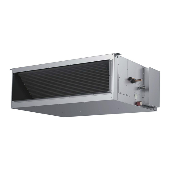
- Page 1 – INSTALLATION AND MAINTENANCE MANUAL – INVERTER-DRIVEN MULTI-SPLIT SYSTEM AIR-COOLED HEAT PUMP AIR CONDITIONERS Ducted Type INDOOR UNITS MODELS HIGH STATIC PRESSURE TYPE RPI-8FSR, RPI-10FSR EN INSTALLATION AND MAINTENANCE MANUAL Original Instructions P5417396...
-
Page 3: Important Notice
Important Notice ● HITACHI pursues a policy of continuing improvement in design and performance in its products. As such, HITACHI reserves the right to make changes at any time without prior notice. ● HITACHI cannot anticipate every possible circumstance that might involve a potential hazard. -
Page 4: Table Of Contents
TABLE OF CONTENTS 1. Introduction ................................1 2. Safety Instructions ..............................1 3. Before Installation ..............................8 3.1 Combination of Outdoor Unit and Indoor Unit ....................8 3.2 Transportation and Handling ........................8 3.3 Factory-Supplied Accessories ........................9 4. Installation Location .............................11 5. -
Page 5: Introduction
● This system should be installed by personnel certified by HITACHI. Personnel must be qualified according to local, state and national building and safety codes and regulations. Incorrect installation could cause leaks, electric shock, fire or explosion. In areas where "Seismic Performance"... - Page 6 This unit is the pressurized system. Never loosen threaded joints while the system is under pressure and never open pressurized system parts. ● HITACHI will not assume any liability for injuries or damage caused by not following steps outlined or described in this manual. Unauthorized modifications to HITACHI products are prohibited as they… ◦...
-
Page 7: Installation Precautions
● Children should be supervised to ensure that they do not play with the appliance. ● Refrigerant and electrical installation work (piping, wiring and additional protection devices) must be done according to the national regulations. ● Install the unit according to provided wiring diagram and connections points indicated in Chapter 8 of this document. -
Page 8: Refrigerant Precautions
As originally manufactured, this unit contains refrigerant installed by HITACHI. HITACHI uses only refrigerants that have been approved for use in the unit’s intended home country or market. HITACHI distributors similarly are only authorized to provide refrigerants that have been approved for use in the countries or markets they serve. -
Page 9: Electrical Precautions
When shielded cable is applied, proper bonding and termination of the cable shield is required as per HITACHI guidelines. Plenum and riser ratings for communication cables must be considered per application and local code requirements. - Page 10 NOTE Additional safety information for R32 refrigerant air conditioner and heat pump according to IEC 60335-2-40: 2018. Explanation of symbols displayed on the indoor unit or outdoor unit. This symbol shows that this equipment uses a flammable refrigerant (A2L). WARNING If the refrigerant is leaked, together with an external ignition source, there is a possibility of ignition.
-
Page 11: Electrical Installation
● Proper handling of this unit requires two-people. Safe handling and installing the indoor unit requires the strength of two people. Mounting the unit alone may cause injury due to fall of the unit. Although the unit may be girded with steel banding, do not use it for transportation. Avoid contact with finned surfaces of the heat exchanger as sharp edges can cause severe injury to hands and fingers. -
Page 12: Before Installation
Before Installation Combination of Outdoor Unit and Indoor Unit The combination capacity of indoor unit against the outdoor unit is selected depending on the outdoor unit capacity. Refer to the “Installation and Maintenance Manual” for the outdoor unit to decide the required combination of indoor and outdoor units, and the combination unit capacity. -
Page 13: Factory-Supplied Accessories
Factory-Supplied Accessories (1) Check to ensure the following accessories are packed with the indoor unit. (Unit: mm) Q’ty Accessory Purpose Usage RPI-8FSR RPI-10FSR Washer (M10) For Unit Installation Washer with Insulation Material (M10) Air Outlet Side Flange For Air Outlet Refer to the item 5.3. - Page 14 NOTICE Wired controller and branch piping are optional accessories and are not included with the indoor unit. If necessary, please contact your contractor. (2) Do not insert or leave any foreign objects inside the indoor unit and verify that no foreign objects remain inside in the indoor unit before the installation and Test Run.
-
Page 15: Installation Location
Installation Location ● Make sure to use the factory-supplied condensate hose and hose clamp. Other makes can cause moisture leakage. ● Do not install the unit where flammable gas may exists. Doing so can result in fire. ● The refrigerant used in this unit does not leak normally. If the refrigerant should leak and come into contact with open flames, toxic gas could be generated. - Page 16 (5) Check if the installation place is suitable for refrigerant piping and electric wiring connection. (6) Do not install the indoor unit near kitchen or the place where humidity is high. Dew condensation may occur during cooling operation. In this case attach additional insulation or etc. (7) Do not install the indoor unit to the atmosphere where filled with organic solvent (paint thinner or benzine) such as painting factory or dry cleaning factory.
-
Page 17: Installation Work
Installation Work Location of Suspension Bolts (1) Determine the final location and installation orientation of the indoor unit with respect to the space allowed for piping, wiring and maintenance. (2) Then cut away the false ceiling area for the indoor unit installation and install suspension bolts. (3) The dimensions for location of suspension bolts are as shown below. -
Page 18: Working Procedure
Working Procedure Air filter is not installed in the unit. Be sure to install air filter. Otherwise, it may cause heat exchanger clog and condensate leakage. (1) Mounting Nuts and Washers Mount nuts and washers onto the suspension bolts before mounting the indoor unit. NOTE: Make sure to use washers (accessories) for installing the suspension bolts to the suspension brackets. - Page 19 (4) Tighten the nuts on the suspension brackets. LOCTITE thread lock compound to the suspension bolts and nuts in order to prevent them from loosening. NOTE: While adjusting the clearance spacing between the indoor unit and the ceiling surface, keep the indoor unit level.
- Page 20 (5) Connecting Return Duct and Supply Duct • Air filter is not attached to the indoor unit. Attach the air filter to the air inlet grille to make the cleaning work easy. • Select the appropriate silencer according to the operation sound to the room installing the unit. If lower sound level is further required, install additional silencer (field-supplied).
- Page 21 (b) Limits on Outdoor Air Intake • Do NOT take outdoor air into the indoor unit directly. If fresh air intake is necessary for air-conditioning facility, HITACHI recommends to install the total heat exchanger. The outdoor air shall be processed by total heat exchanger and mixed with indoor air.
-
Page 22: Installation Of Optional Parts Or Field-Supplied Parts
Installation of Optional Parts or Field-Supplied Parts (1) Refer to the manual for each parts for the installation of canvas duct, air outlet duct, flexible duct, motion sensor and etc.. NOTE: (1) Install flexible duct to all air outlets without bending so that air flow is not disturbed. Clogging air outlets or bent flexible duct may cause operation failure or stoppage, sweating and dripping. -
Page 23: Refrigerant Piping Work
(2) Select the piping size from the following table. Table 6.1 Piping Size (mm) Model Gas Piping Liquid Piping f19.05 f9.52 RPI-8FSR (f25.4*) f22.2 f9.52 RPI-10FSR (f25.4*) (f12.7*) NOTE: * The refrigerant piping diameter may be changed according to the outdoor unit to be combined. -
Page 24: Piping Connection
(4) Prepare field-supplied copper pipes. (5) Select clean copper pipes. Make sure there is no dust or moisture inside. (6) The refrigerant oil for the refrigerant R410A is susceptible to moisture, an oxide film, and fatty oil. Take special care during the installation so that moisture, contaminations or old refrigerant oil will not enter the refrigerant cycle. - Page 25 (4) After connecting the refrigerant piping, seal the refrigerant pipes by using the factory supplied insulation material as shown below. Unit: mm Brazing Fasten with code clamps (Accessory) at Pipe Insulation (φ25, L=110) 3 locations along the pipe. Liquid Side Pipe Insulation: φ48, L 200 (Accessory) Indoor Unit (Accessory) Gas Side Pipe Insulation: φ63, L 200 (Accessory)
-
Page 26: Refrigerant Piping For R32
Refrigerant Piping for R32 (1) Refrigerant piping length between indoor unit and Refrigerant Amount Minimum Area outdoor unit (kg) 1.84 2.14 The unit installation and refrigerant piping should comply with the relevant local and national regulations for the 2.29 designed refrigerant. 2.53 Due to R32 refrigerant and depending on final refrigerant 2.79... -
Page 27: Drain Piping
Drain Piping Do not run drain piping into underground areas near sanitary or sewage lines where toxic and corrosive gas can seep into the system. This creates a pathway for the flow of poisonous gas to penetrate inhabited areas. NOTICE ●... - Page 28 (c) Attach the factory-supplied hose clamp to the vinyl tape (white) attached to the drain hose. The hose clamp shall be 20mm away from the end face of the drain hose. Then tighten the hose clamp to make sure that it is approximately 28mm in length from the screw to the edge of the hose clamp as shown in the figure below.
- Page 29 (g) Installing Common Drain Piping ● Install the common drain pipe on a downward slope to make sure that it is lower than each rising part of the drain pipe from the indoor unit. ● The size for the common drain pipe must be VP30 or more (nominal diameter 30mm, outer diameter 38mm) according to the number of the connected indoor units.
- Page 30 ● Moisture which has discharged into the drain pan and check for drainage in the heating season should be drained completely from the drain pan. ● The heat exchanger is heated since the slight amount of refrigerant circulates inside the indoor unit during stoppage.
-
Page 31: Electrical Wiring
Electrical Wiring ● All electrical work must be done as outlined in this manual and in accordance with this manual. Substandard work can result in fire and damage to the unit. ● Use specified cables between units and choose the cables correctly. If not, an electrical shock or fire may occur. -
Page 32: Electrical Wiring Capacity
3) The wire sizes marked with *2 in the above table are selected at the maximum current of the unit according to the wire, MLFC (Flame Retardant Polyflex Wire) manufactured by Hitachi Cable Ltd., Japan. 4) Use a shielded cable for the transmitting circuit and connect it to ground. -
Page 33: Details Of Electrical Wiring Connection
8.2.2 Details of Electrical Wiring Connection The electrical wiring capacity of the outdoor unit should be referred according to “Installation & Maintenance Manual” of the outdoor unit. Setting DIP Switch may be required depending on the combination with the outdoor unit. NOTE: When installing the unit in Australia, connect the both ends of shielded twist pair cable (controller cable and control cable) to the earth. - Page 34 < Case B > l Wiring Connection (Single Indoor Unit) Power Source Type: 3 Phase 4 Wires < 3f 380-415V/50Hz, 3f 400V/50Hz > 380V-415V / 50Hz 220-240V / 50Hz 400V/50Hz (3N~) *1, *2 Wired Controller (Option) Main Main Switch Switch Outdoor Unit Indoor Unit L2 L3 N...
- Page 35 Table 8.1 Recommended Wiring Capacity and Size for UTOPIA Series Model Main Switch Wiring Capacity (mm Transition Wiring Rated Rated Fuse Power between O.U. and I.U. Current Current Capacity Source Earth Controller Power Cable Wiring Cable Control Combination Supply Circuit Indoor Indoor Indoor...
- Page 36 (manufactured by HITACHI Cable Co. Ltd.)) or 2-core twist pair cable (equivalent to following cables: KPEV or KPEV-S (manufactured by HITACHI Cable Co. Ltd.)) for the control cable between the outdoor unit and the indoor unit. The total cable length should be less than 1000m.
-
Page 37: Position Of Electrical Wiring Connection
Position of Electrical Wiring Connection l Ensure that the wiring terminals are tightened securely with the specified torques. Loose terminals may cause heat generation at the terminal connection part, a fire or an electric shock. l Fix the cables securely. External forces from the cables applied on the terminals could lead to heat generation and a fire. - Page 38 (7) Perform wiring work for the indoor unit according to the electrical wiring diagram and “Installation and Maintenance Manual” of the outdoor unit. (8) In Case that Power Source Is Applied to Control Line If the power source is applied to the control line (Terminal 1 and 2 of TB2) by mistake, the fuse on the PCB for the control line will blow out.
- Page 39 l For SET FREE Series (a) Installing Wired Controller to each Unit for Individual Operation Setting Indoor Unit Indoor Unit Outdoor Unit Wired Wired Controller Controller (b) Installing One Wired Controller to Multiple Units for Individual Operation Setting Indoor Unit Indoor Unit Outdoor Unit Wired...
-
Page 40: Transition Wiring For Wired Controller
Transition Wiring for Wired Controller 8.4.1 Cautions for Motion Sensor Kit (1) The motion sensor can be connected up to 16 indoor units by one wired controller. The motion sensor will be activated even if it is installed without motion sensor. (2) When the multiple indoor units with motion sensor are controlled by one wired controller, the transition wiring for wired controller is required to all the indoor units. -
Page 41: Caution For Electrical Wiring
< Use Conditions and Precaution Statements > (1) The motion sensor detects the change of the infrared light. Therefore, it may detect the moving objects such as small animals which are difference in temperature against atmosphere. Additionally, it may detect as absence in the case of staying for long time with a bit motion or a rapid motion. DO NOT install the motion sensor kit in the following places. -
Page 42: Wiring Connections
Wiring Connections The wiring connections for the indoor unit are shown in the figures below. PCB2 Terminal Blocks Ground Wiring Connection Screw PCB1 (M5) Cutout for Power Supply Wiring Cable Clamp Cutout for Controller Cable and Communication Cable Power Supply Wiring Controller Cable Communication Cable between Indoor Unit and Outdoor Unit... -
Page 43: Dip Switch Settings
DIP Switch Settings (1) Turn OFF the power supply to both indoor and outdoor units before adjusting DIP switch settings. Otherwise, the settings will be invalidated and not take effect. (2) Positions of DIP Switches on the PCB are shown in the figure below. DSW4 RSW1, DSW5 (Unit Model Code Setting) -
Page 44: Function Selection By Wired Controller
Refrigerant Cycle No. Setting (6) Refrigerant Cycle No. Setting (RSW1 & DSW5) DSW5 (Tens Digit) RSW1 (Units Digit) Ex.) Set at No.5 Cycle This setting is required. The unit arrives with all DSW5 Setting Set by inserting settings in the OFF position. Position slotted screwdriver into the groove. -
Page 45: External Static Pressure Setting
External Static Pressure Setting The factory setting of external static pressure is set to Standard. The setting can be changed to High Pressure Setting 1 or High Pressure Setting 2. Follow the procedure below after activating the wired controller. ● Set external static pressure using wired controller. (1) Press and hold "Menu"... -
Page 46: Test Run
Test Run Before Test Run Verify that there are no problems with the installation, and do not perform Test Run until all the following conditions have been resolved. Refer to the "Installation and Maintenance Manual" for the outdoor unit for details on Test Run operations from the outdoor unit. - Page 47 ● The total number of connected indoor units is indicated on the LCD (Liquid Crystal Display). In the case of a twin combination (set of two indoor units), the total number of the connected indoor units is displayed as “2 units”, and where there is a triple combination (set of three indoor units), the total number of the connected indoor units is displayed as “3 units”.
- Page 48 Checking the Motion Sensor 1. Perform a motion detection action (such as waving a hand) under the motion sensor of the selected indoor unit for approximately 10 to 15 seconds. 2. Check the value of “q1" after 30 seconds (*1) from starting the motion detection at Step 1.
-
Page 49: Alarm Code
Alarm Code Alarm (Troubleshooting) Code Table Code Category Nature of Problem Likely Cause Activation of the float switch; (High water level present in Activation of a protection device Indoor Unit (Float switch) the condensate pan.) A problem exists in the piping. Activation of protection device;... -
Page 50: Safety And Control Device Setting
Then hand it over to users and ask them to retain for reference. All periodic service and maintenance procedures must be conducted only by authorized and trained personnel. 10. Safety and Control Device Setting Model RPI-8FSR, RPI-10FSR For Control Circuit Fuse Capacity... - Page 52 © 2021 Hitachi-Johnson Controls Air Conditioning, Inc. P5417396, 2021 Printed in Japan...
Need help?
Do you have a question about the RPI-8FSR and is the answer not in the manual?
Questions and answers