
Related Manuals for LDA Audio Tech NEO+


Summary of Contents for LDA Audio Tech NEO+
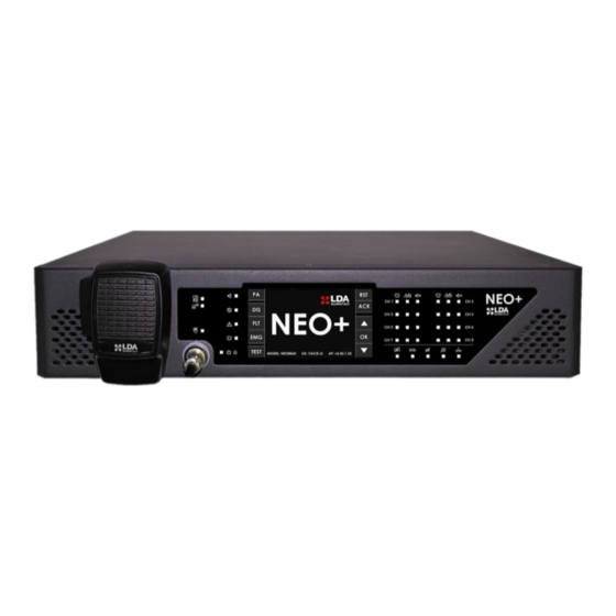
- Page 1 User’s Manual EN 54-16 certified Voice Alarm System for Evacuation and Public Address LDA NEO+...
-
Page 2: Safety Instructions
SAFETY INSTRUCTIONS Please read these safety instructions carefully. Save this user manual for future reference. Power connectors must be accessible for disconnection and where people cannot step on or trip. Disconnect the equipment from the AC/DC (AC) outlet before cleaning it. The appliance must not be exposed to falling water or splashes and no liquid-filled objects should be placed on the appliance. -
Page 3: Table Of Contents
INDEX 1 INTRODUCTION ............................6 System features ........................6 2 DESCRIPTION ............................7 Frontal. Indicators ........................7 2.1.1 General state indicators ....................... 8 2.1.2 Channel state indicators ...................... 9 2.1.3 Supervised functions indicators..................9 2.1.4 Emergency sources indicators .................... 9 Controls ........................... - Page 4 3.4.4 Speaker lines supervisión ....................29 3.4.5 Line terminators ......................... 29 3.4.6 Volume control - Attenuators .................... 30 Backup amplification ......................31 Voice evacuation zones ......................31 Main backup unit ........................31 4 SYSTEM OPERATION ........................... 33 First power-on ......................... 33 Emergency control .........................
- Page 5 7 TECHNICAL FEATURES ........................52 APPENDIX INDEX Appendix I. EN54-16 functions ......................54 Appendix II. Log content ........................55 Appendix III. Network configuration on NEO+ systems ..............58 Appendix IV. Cable section for speaker lines ..................59...
-
Page 6: Introduction
4GB of memory for pre-recorded messages (more than 600 minutes). • Integrated emergency microphone. • Control for up to 32 LDA AT-6 attenuators. • Integrated front speaker for monitoring. • 24 GPIO ports (10 monitored for integration in the Central Fire Alarm Panel). Rev.0 © LDA Audio Tech 2024... -
Page 7: Description
Ethernet connection and expand the number of zones, Available amplifiers and lines including the required and certified functions as system elements EN 54-16. 2.1 Frontal. Indicators CH 1 CH 2 CH 3 CH 4 CH 5 CH 6 CH 7 CH 8 Illustration 1: Indicators Rev.0 © LDA Audio Tech 2024... -
Page 8: General State Indicators
This warning can be muted by the "ACK" control, or automatically when using the emergency microphone. "DISARMED". Amber On: when any area of the voice alarm zones is deactivated. "PUBLIC ADDRESS". White On: Normal PA operation. The system is not in emergency state. Rev.0 © LDA Audio Tech 2024... -
Page 9: Channel State Indicators
On: when the computer’s firmware or memory fails to run. Reset the failure condition. If the problem persists, see chapter 5.6 for resolution. Amber color. 2.1.4 Emergency sources indicators Emergency source indicators indicate the operating state of pre-recorded messages, and the emergency microphone. Rev.0 © LDA Audio Tech 2024... -
Page 10: Controls
Allows access to the PA menu when equipment is at rest, that is, if there is no emergency state. It also allows the back function to be used for menu navigation. The "PA" button will change to "BACK" button when the return option is available. Rev.0 © LDA Audio Tech 2024... -
Page 11: Scroll Controls
The title of the section in which the user is operating will be indicated at the top of the window. (c) ACCESS LEVEL The current access level indicator is located in the upper right corner of the screen (see 2.3). Rev.0 © LDA Audio Tech 2024... -
Page 12: Zone Selection Window
Yellow rectangle on the left side of the zone button. In illustration 4 zone 4 (d) NO SELECTED AREA No selection band. In illustration 4, zones 5 and 6 where zone 8 cannot be selected by default once deactivated (see 4.4). Rev.0 © LDA Audio Tech 2024... -
Page 13: User Profiles. Access Level. Password
Level 3 access corresponds to the profile of system administrator user, with specific training that allows you to modify the configuration of the equipment/system, and perform the specified maintenance, according to the instructions and data in this manual. Rev.0 © LDA Audio Tech 2024... -
Page 14: Rear Panel. Inputs And Outputs
NC meaning of each manufacturer. E.g. LDA devices indicate N.O. on the pins where the circuit is normally open (no failure). The SONAES charger used with NEO+ indicates otherwise, so you have to cross the pins NO and NC. Rev.0 © LDA Audio Tech 2024... -
Page 15: Emergency Activation Interface
The connection is made by a female Euroblock connector with 4 contacts and 3.81 mm pitch (supplied with the equipment). The cable cross-section range for each pole of this connector is: 0.14 → 1.5 mm (30 → 14 AWG). Rev.0 © LDA Audio Tech 2024... - Page 16 0.14 → 1.5 mm2 (30 → 14 AWG). Brand Description Type Signals Activation Emergency state activation input in Dry contact closure Input ┴ zone x Supervised Input Table 4: Emergency Input by zone Rev.0 © LDA Audio Tech 2024...
-
Page 17: Interface Speaker Line Device
The equipment has a connection bay where it integrates an ETX-3 module, which allows the connection to both public address systems and integrate third party systems. The ETX-3 module is supplied as standard equipment. Illustration 15: System Connection Bay Rev.0 © LDA Audio Tech 2024... - Page 18 System connection ports Port Proprietary command protocol CAT 5 Table 8: System connection ports (d) USB port (reserved) The USB port (mini-USB type AB) available on the computer is reserved. Illustration 16: Mini-USB port Rev.0 © LDA Audio Tech 2024...
-
Page 19: Power Supply
Illustration 19: Main power supply input Description Type Signals Activation 220-240 V/110-120 V ~ 50/60 Hz Connection for main power supply Input L N G (according to selector) Table 11: Main power input Rev.0 © LDA Audio Tech 2024... -
Page 20: Speaker Lines
A and B. The nominal power of the amplifier channel is distributed between both line outputs. For details on connecting speaker lines see Chapter 3.4. Each line connection has two + and - terminals for connecting speakers on 100 V or low impedance PA lines depending on the model. Rev.0 © LDA Audio Tech 2024... -
Page 21: Audio Source Inputs And Outputs
The connection is made by a 4-pin female Euroblock connector with 3.81 mm pitch (supplied with the equipment). The cable cross-section range for each pole of this connector is: 0.14 → 1.5 mm (30 → 14 AWG). Rev.0 © LDA Audio Tech 2024... - Page 22 (d) LINE LEVEL AUDIO OUTPUTS The equipment has 8 line level balanced audio outputs, one for each amplification channel, whose signal is identical to that delivered to the input of the amplifiers integrated in the equipment. Rev.0 © LDA Audio Tech 2024...
-
Page 23: Audio Inputs
NEO+ 4500LE for professional Live audio, with the advantage that in case of evacuation there will always be room for the emergency sources of the NEO+ system. This will also allow the sound reinforcement system to be used for evacuation. Rev.0 © LDA Audio Tech 2024... -
Page 24: System Integration Ports
(30 → 14 AWG). Brand Description Type Signals Activation Serial port for RS-485 integration 485-AB Port Standard RS-485/9600/8/N/1* Terminal A and B 485 ┴ Chassis or cable shield Table 21: Advanced ECI integration port Rev.0 © LDA Audio Tech 2024... -
Page 25: Connection And Start-Up
NO and NC meaning of each manufacturer. E.g. LDA devices indicate N.O. on the pins where the circuit is normally open (no failure). The SONAES charger used with NEO+ indicates otherwise, so you have to cross the pins NO and NC. Rev.0 © LDA Audio Tech 2024... -
Page 26: Microphones And Acsi Devices
(see ¡Error! No se encuentra el origen de la referencia.) 3.3 FlexNet Connection FlexNet is a communication protocol developed by LDA Audio Tech, designed to transmit digital audio and control data over standard Ethernet networks. This system offers high quality and reliability, the audio transmission is based on the open standard AES67 protocol and for the control of the system an IP-based protocol has been developed. -
Page 27: Speaker Lines
In Appendix IV: Cable section for speaker lines you can find a guide table for the calculation of the cable cross-section to be used in the installation according to the power and length of the cable. Rev.0 © LDA Audio Tech 2024... -
Page 28: Standard Mode Wiring
When an open circuit fault is detected, the backup line (branch B) is activated. If the failure persists, then one measurement per separate branch is performed. It is recommended to locate the line terminator at the physical point of the line furthest from the equipment. Rev.0 © LDA Audio Tech 2024... -
Page 29: Speaker Lines Supervisión
This way, the line end terminal will be connected to the computer according to the following scheme: Rev.0 © LDA Audio Tech 2024... -
Page 30: Volume Control - Attenuators
NOTE: After a volume controller, no line terminator should be connected as this may cause failures in the speaker line fault detection system. NOTE: For more information about the volume controller, AT Series, please consult LDA Support website. Rev.0 © LDA Audio Tech 2024... -
Page 31: Backup Amplification
NEO+ provides redundancy to the system with a second master controller that can automatically replace the main controller live. This feature is designed especially for large systems, where it is important to reduce the times when system controller is unavailable to zero. Illustration 41: Redundant controller window Rev.0 © LDA Audio Tech 2024... - Page 32 In addition, the loss of the main controller is recorded, giving notice to intervene as soon as possible and proceed with its review. Rev.0 © LDA Audio Tech 2024...
-
Page 33: System Operation
To issue an evacuation warning, the system must be in a state of emergency. The following types of warning may be issued from this mode of operation: • Recorded alert message. • Recorded evacuation message. • Live message from emergency microphone. Rev.0 © LDA Audio Tech 2024... -
Page 34: Activate Voice Alarm
To make a new selection you will first be asked to deactivate the current selection, so the text "CLEAR EMIC ZONES" will appear in this option. Once pressed, the selection can be repeated by pressing "SELECT EMIC ZONES" Rev.0 © LDA Audio Tech 2024... -
Page 35: Stop Voice Alarm
To view all records, use the up and down scroll control to move through the window. The history record can be accessed through the configuration application. You can see a description of all the records in Appendix II. Rev.0 © LDA Audio Tech 2024... -
Page 36: Voice Evacuation Zone Volume Adjustment
The equipment/system has features to disable voice alarm zones that are not going to be used. Once disabled, they will be displayed in the menus as described in chapter 2.2.7(e). No operation shall be possible on a disabled area. Indications of emergency or fault states shall not be displayed. Rev.0 © LDA Audio Tech 2024... -
Page 37: Disable/ Enable Zone
Press the "PA" shortcut button, access control for level 2 users will appear (see 2.3). If you want to go back, press the "BACK" key. After the access control has been passed, the access authorization Rev.0 © LDA Audio Tech 2024... -
Page 38: Zone Volume Setting
(d) VOLUME INDICATOR The volume indicator ranges from -100dB to 0dB, minimum and maximum zone volume respectively. If a zone is selected, the current volume level will be displayed and updated as the adjustment is Rev.0 © LDA Audio Tech 2024... -
Page 39: Route Sources
(see 4.5.7) and start playing the corresponding message. (c) SELECTION INDICATOR When the font has been selected, a selection strip will appear inside the font button. Rev.0 © LDA Audio Tech 2024... -
Page 40: Advanced Options
(d) MESSAGES Access to the prerecorded messages playback window (e) LOAD PRESET Access to the system memory selection window. To configure the system’s operating memory, you must use the configuration application. Rev.0 © LDA Audio Tech 2024... -
Page 41: Advanced Options. Audio Input
"OK". If you wish to cancel the operation, press the "BACK" key. Rev.0 © LDA Audio Tech 2024... -
Page 42: Advanced Options. Audio Output
If you wish to cancel the operation, press the "BACK" key. When the gain to be applied to the output reaches its lower or upper limit of output adjustment (-100 - 0dB), it will lock. Thus, an output with a Rev.0 © LDA Audio Tech 2024... -
Page 43: Advanced Options. Monitor
NOTE: If the music source input 5 is being used as a multi-zone microphone input, it will also be monitored when any of the microphones press to speak for any of the system zones. Rev.0 © LDA Audio Tech 2024... -
Page 44: Advanced Options. Messages
(h) ADJUSTMENT BUTTONS The window has two buttons for adjusting the volume of the built-in monitor speaker: "+" and "-", each time you press one of them will increase or decrease 1 decibel. Rev.0 © LDA Audio Tech 2024... -
Page 45: Advanced Options. Load Preset
To load a preset, select it by clicking on it. To confirm press the "OK" key. NOTE: You can use the configuration application to create, edit and delete presets for your computer. Rev.0 © LDA Audio Tech 2024... -
Page 46: Advanced Options. System
(f) NETWORK SETTINGS BUTTON The network settings button, allows access to the configuration of the computer’s network parameters, as shown in the following image. NOTE: You must press OK (green) on the image keyboard to save changes. Rev.0 © LDA Audio Tech 2024... - Page 47 Extensions will not be recognized by the Master during the search. When the selection is on a computer other than number 1 (NEO+ Master), this button changes, allowing to remove the selected NEO+ Extension from the system. Rev.0 © LDA Audio Tech 2024...
-
Page 48: Resolution Of Fault Indications
2. Check that the air inlets and outlets are not blocked. 3. Turn off the computer and wait several minutes before turning it back on. If the equipment is restarted, avoid this mode of operation as it may cause severe failure. Rev.0 © LDA Audio Tech 2024... -
Page 49: Power Supply
(see 4.5.9). 2. Restart the computer that appears down. 3. If the problem persists, check that the connection between the two is correct according to paragraph 3.2. For more details see NETWORK LOG. Rev.0 © LDA Audio Tech 2024... -
Page 50: System
3. Do not forget to restore the backup with the location data after you have done the restore. After this operation, the equipment should be running normally. If not, please contact the support or repair service for additional assistance. For more details see SYSTEM LOG. Rev.0 © LDA Audio Tech 2024... -
Page 51: Maintenance Instructions
Disconnect the computer from any external power supply. • Disconnect all external devices. • Keep the product away from any liquid. • Do not use aerosols, solvents or abrasive substances. • Do not spray any cleaner directly on the appliance Rev.0 © LDA Audio Tech 2024... -
Page 52: Technical Features
Flexible power distribution: 8 x 120W; 6 x 250W. Potencia EN54-16: 112Wrms NEO+ 4250E Class D. 4 channels up to 500W. Min charge. 20Ω@100V/70V. Max total charge. 1000W Flexible power distribution. 4 x 250W; 2 x 500W. Power EN54-16: 500Wrms Rev.0 © LDA Audio Tech 2024... - Page 53 483 mm x 88 mm x 455mm/ 19" x 3.46" x 18" (2U rack) Accessories 2 x Rack mount, Euroblock male type connectors, Installation screws, 4 x rubber feet, 1x Power cable 2m/ 6.56 ft (EU type), 1x Ethernet cable 2m/ 6.56ft Rev.0 © LDA Audio Tech 2024...
-
Page 54: Appendix I. En54-16 Functions
Independent audio signal processing per I/O channel Pre-recorded message player Realzador de sonido LDA (“LDA Sound Enhancer”) Output of recording Control output for dimmers 7-band input parametric equalizer per channel 7-band output parametric equalizer per channel 10 Loudness compensation Rev.0 © LDA Audio Tech 2024... - Page 55 For troubleshooting see paragraph 5.2 AMPLIFIER SUPERVISION LOG Description Protect fault Amp Ch X Failure of the "X" channel amplifier Protect fault fuse X Internal protection failure related to the "X" channel amplifier Table 24: Amplifier supervision log Rev.0 © LDA Audio Tech 2024...
-
Page 56: Network Log
Failure in a physical memory component: EEPROM_ETX, SD_ETX or SD_FR. Remote system fault on device X Indicates a critical hardware or system failure in an extension. Table 27: System log For troubleshooting see paragraph 5.6 Rev.0 © LDA Audio Tech 2024... - Page 57 Failure I2C communication between front and ETX I2C FAILURE 2002 Front SD memory failure INTERNAL MEMORY FAILURE 2003 SD ETX memory failure INTERNAL MEMORY FAILURE 2004 Fallo memoria sistema INTERNAL MEMORY FAILURE Table 30: Critical system errors Rev.0 © LDA Audio Tech 2024...
-
Page 58: Factory Network Configuration
232.0.1.21 01:00:5E:00:01:15 FlexNet+ Loop Supervision 232.1.1.21 01:00:5E:01:01:15 FlexNet+ Loop Supervision (backup) 232.1.1.84 01:00:5E:01:01:54 Multicast IGMP 224.0.0.1 01:00:5E:00:00:01 LDA AES Streams (NEO+ y NEXOs02) [232.1.1.100-232.255.1.100] Default streams of NEXOs01 (IPBOX) [239.3.208.1-239.3.208.16] Table 31: IP addressing Rev.0 © LDA Audio Tech 2024... - Page 59 Table 32: Cable section for 100V lines Legend: • AWG (American Wire Gauge): American Cable Gauge. Diameter classification according to USA standard. • Ø mm: Cable diameter in millimetres. • : Area of the cable cross-section in square millimetres. Rev.0 © LDA Audio Tech 2024...
- Page 60 Illustration 46: Log Disarm window ....................... 37 Illustration 47: PA menu window......................38 Illustration 48: Zone volume adjustment window ................. 38 Illustration 49: Sound source selection window ................... 39 Illustration 50: Advanced menu window ....................40 Rev.0 © LDA Audio Tech 2024...
- Page 61 Illustration 52: Audio output adjustment window ................. 42 Illustration 53: Monitor window ......................43 Illustration 54: Message window ......................44 Illustration 55: Window load preset ....................... 45 Illustration 56: System window ......................46 Illustration 57: Network Configuration Window ..................47 Rev.0 © LDA Audio Tech 2024...
- Page 62 Table 28: Emergency microphone log ....................57 Table 29: ACSI device log ........................57 Table 30: Critical system errors ......................57 Table 31: IP addressing .......................... 58 Table 32: Cable section for 100V lines ....................59 Rev.0 © LDA Audio Tech 2024...
Need help?
Do you have a question about the NEO+ and is the answer not in the manual?
Questions and answers