Table of Contents
Advertisement
Quick Links
Advertisement
Table of Contents

Related Manuals for LDA Audio Tech Neo VAP 1


Summary of Contents for LDA Audio Tech Neo VAP 1
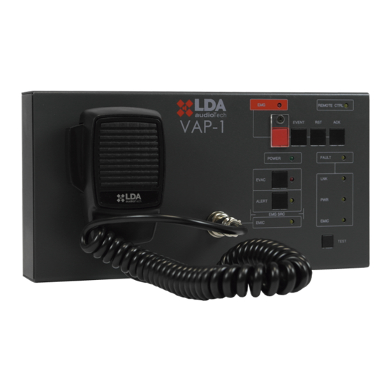
- Page 1 User’s Manual Model: VAP 1...
- Page 3 SAFETY INSTRUCTIONS 1. Please read these safety instructions carefully. 2. Keep this User's Manual for future reference. 3. Unplug the equipment from the AC power supply before cleaning. 4. Do not use liquid or aerosol cleaners. Do not allow the unit to get wet. 5.
-
Page 5: Table Of Contents
Table of Contents 1 INTRODUCTION........................... 1 2 DESCRIPTION..........................1 2.1 INDICATORS..........................2 2.1.1 GENERAL CONDITION INDICATORS..................2 2.1.2 SUPERVISED FUNCTIONS INDICATORS................... 2 2.1.3 EMERGENCY ALERT SOURCE INDICATORS................3 2.1.4 SELECTION INDICATORS......................3 2.2 CONTROLS..........................3 2.2.1 EMG............................... 3 2.2.2 RESET............................4 2.2.3 ACK.............................. -
Page 7: Introduction
10. Indicator of voice evacuation recorded message emission 11. Indicator of voice alert recorded message emission 12. Remote control indicator 13. Emergency, reset, acknowledge, test, alert message and evacuation message controls LDA Audio Tech - Severo Ochoa, 31- 29590 MALAGA, SPAIN. Tel: +34 952028805 www.lda-audiotech.com/en... -
Page 8: Indicators
2.1 INDICATORS Illustration 1: Indicators 2.1.1 GENERAL CONDITION INDICATORS Condition indicators show at all times the operating condition of the equipment or system. (a) EMG: "EMERGENCY" Active (on) when the equipment is in an emergency operation condition (voice alarm), either by manual or automatic activation from the ECI of any voice alarm zone. When in the emergency condition a warning voice is being issued, whether through emergency microphone or through recorded evacuation message, the indicator will light up intermittently. -
Page 9: Emergency Alert Source Indicators
Zone extensions for the Voice Alarm Panel feature zone memory selection indicators. When selected by pressing the corresponding key, the indicator next to it activates (on). Green color. LDA Audio Tech - Severo Ochoa, 31- 29590 MALAGA, SPAIN. Tel: +34 952028805 www.lda-audiotech.com/en... -
Page 10: Controls
2.2 CONTROLS Illustration 2: Controls 2.2.1 EMG The EMG button, red color, is located in the upper left part of the equipment. It offers protection against accidental pushing. It allows to change the system condition to evacuation mode. 2.2.2 RESET The "RESET"... -
Page 11: Test
ACSI bus directly. If the selector is in the 24V position, the VAP 1 will be supplied exclusively from the ACSI bus. LDA Audio Tech - Severo Ochoa, 31- 29590 MALAGA, SPAIN. Tel: +34 952028805 www.lda-audiotech.com/en... -
Page 12: Keyboard Identificator
2.2.10 KEYBOARD IDENTIFICATOR Illustration 4: Keyboard identificator The keyboard identifier is only available in expansion keyboards attached to the VAP 1. "ID" is located in the middle of the base of the equipment. It allows to choose the position of the expansion keyboard in the set. -
Page 13: Pa System Input/Output
The unit has an input for auxiliary power supply. Emergency stress is continuous and has a nominal value of 5V that will be externally supplied to the computer using a USB charger provided with the machine. MiniUSB female connector. LDA Audio Tech - Severo Ochoa, 31- 29590 MALAGA, SPAIN. Tel: +34 952028805 www.lda-audiotech.com/en... -
Page 14: Ports For Expansion Keyboards
Illustration 7: Supply/Update input Mark Description Type Signals Activation 4,5 – 5,5V DC External supply input Port USB 1.1 Current: 200 – 500 mA Table 2: External supply input The connection is made with a miniUSB A male cable (provided with the equipment). 2.3.3 PORTS FOR EXPANSION KEYBOARDS The equipment has a port on the right side of the unit for connecting additional keyboards. -
Page 15: Operation Description
NOTE: The previous zone memories selection will disappear when you make a new selection. LDA Audio Tech - Severo Ochoa, 31- 29590 MALAGA, SPAIN. Tel: +34 952028805 www.lda-audiotech.com/en... -
Page 16: Stopping Voice Warning
3.2.3 STOPPING VOICE WARNING To stop the issuance of a warning voice, in case it is a recorded message, push the button of the message that hat you want to stop. To stop the live voice warning release the "Talk" button on the microphone. -
Page 17: Connection And Setting Up
"REMOTE CTRL" and "EMG" indicators. The configured bus address will be indicated with the lighting of the fault and "EMIC" indicators as shown in the table 4: LDA Audio Tech - Severo Ochoa, 31- 29590 MALAGA, SPAIN. Tel: +34 952028805 www.lda-audiotech.com/en... -
Page 18: Vap 1 Configuration
Illustration 10: ACSI Bus Address Signal INDICATOR FAULT INDICATORS ADDRESS EMIC FAULT EMIC Table 4: ACSI Bus Address Signal • Push the recorded message "EVAC" and "ALERT" buttons to increase or decrease the equipment address. With each tap the new address will be shown in the indicators, as shown in the table 4. -
Page 19: Configuration. Output Volume
Set the expansion keyboard ID as described in section 2.2.10. • Reconnect the VAP 1 to the system. By default, the new keys will take the zones of the system as described in section 2.2.10. LDA Audio Tech - Severo Ochoa, 31- 29590 MALAGA, SPAIN. Tel: +34 952028805 www.lda-audiotech.com/en... - Page 20 Illustration 11: Expansion Keyboard Connection. Step 1 Adaptor Illustration 12: Expansion Keyboard Connection. Step 2 Illustration 14: Expansion Keyboard Connection. Step 3 Illustration 13: Expansion Keyboard Connection. Step 4 Block www.lda-audiotech.com/ en...
-
Page 21: Update
The update process is automatically made from the NEO equipment to the ACSI devices. This may take a few minutes depending on the device and the system. During this time the device will not be operational. LDA Audio Tech - Severo Ochoa, 31- 29590 MALAGA, SPAIN. Tel: +34 952028805 www.lda-audiotech.com/en... -
Page 22: Installation
6 INSTALLATION 6.1 INSTALLATION FOR THE 19'' RACK The VAP 1 is provided with accessories for its installation in a 19'' rack that must be attached to the rear part of the equipment with 4 M4 screws. To adjust the width of the equipment, you can use expansion keyboards or rack complements. -
Page 23: Fault Resolutions
Check that the last bus equipment has the "Bus Terminator" option on, according to section 2.2.8 Connect the auxiliary power supply provided with the equipment, in case the VAP 1 is directly supplied from the ACSI bus LDA Audio Tech - Severo Ochoa, 31- 29590 MALAGA, SPAIN. Tel: +34 952028805 www.lda-audiotech.com/en... -
Page 24: Remote Ctrl" And "Emg" Indicators Blink Simultaneously
Make sure the connection between the equipment and the system has been carried out correctly according to section 4.2. To debug the fault, disconnect both ends of the two bus cables connected between the system and the equipment, and measure between each of the cable Ω... -
Page 25: Expansion Keyboards Do Not Address The Zones
Disconnect all external devices. • Keep away from liquids • Do not use aerosol sprays, solvents, or abrasives. • Do not spray cleaner directly on the device • LDA Audio Tech - Severo Ochoa, 31- 29590 MALAGA, SPAIN. Tel: +34 952028805 www.lda-audiotech.com/en... - Page 26 Operations: Wipe with a damp cloth • Clean the air inputs and outputs with a vacuum cleaner. • Check the connections of the equipment. • www.lda-audiotech.com/ en...
-
Page 27: Technical Features
Expansion keyboard accesories 1 x expansion port adaptor 2 x 5 contacts male-male 1 x connecting piece to VAP 1 4 x countersunk screw (4 x 8 mm LDA Audio Tech - Severo Ochoa, 31- 29590 MALAGA, SPAIN. Tel: +34 952028805 www.lda-audiotech.com/en... - Page 28 Ver. 2...
Need help?
Do you have a question about the Neo VAP 1 and is the answer not in the manual?
Questions and answers