Table of Contents
Advertisement
Quick Links
SEER2 WALL MOUNTED AIR HANDLER SYSTEM TECHNICAL MANUAL
Technical Manual
CWM4 & BAR4 Series
SEER2 Wall Mounted Air Handler & Condensing Units
R410A 208/230V 1Ph 60Hz
IMPORTANT NOTE:
Read this manual carefully before operating your
new air conditioning unit. Make sure to save this
manual for future reference.
Please check the applicable models, technical data,
F-GAS(if any) and manufacturer information from the "Owner's
Manual " in the packaging of the outdoor unit.
Advertisement
Table of Contents

Related Manuals for ComfortStar CWM4 Series


Summary of Contents for ComfortStar CWM4 Series
- Page 1 SEER2 WALL MOUNTED AIR HANDLER SYSTEM TECHNICAL MANUAL Technical Manual CWM4 & BAR4 Series SEER2 Wall Mounted Air Handler & Condensing Units R410A 208/230V 1Ph 60Hz IMPORTANT NOTE: Read this manual carefully before operating your new air conditioning unit. Make sure to save this manual for future reference.
-
Page 2: Table Of Contents
SEER2 WALL MOUNTED AIR HANDLER SYSTEM TECHNICAL MANUAL P a rt 1 . G en e ral Info rm a tio n ......................1 1. Model Names of Indoor/Outdoor Units ................ 1 2. External Appearance ...................... 3 3. Features ..........................4 P a rt 2 . -
Page 3: P A Rt 1 . G En E Ral Info Rm A Tio N
SEER2 AIR HANDLER SYSTEM TECHNICAL MANUAL P a rt 1 . G e n e ra l In fo rm a tio n 1. Model Names of Indoor/Outdoor Units ..........2 2. External Appearance ................3 3. Features ..................... 4... - Page 4 SEER2 AIR HANDLER SYSTEM TECHNICAL MANUAL 1 . M o d e l N a m e s o f In d o o r/O u td o o r U n its 1.1 In d o o r U n its M o d el n am e D im en sio n (W ×...
-
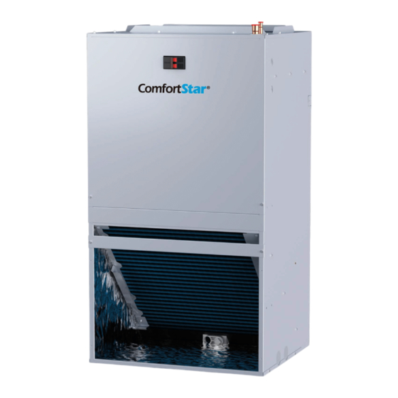
Page 5: External Appearance
SEER2 AIR HANDLER SYSTEM TECHNICAL MANUAL 2 . E x te rn a l A p p e a ra n c e 2.1 In d o o r u n it 2.2 O u tdo o r u n it N o te : S tan d a rd o utd o o r u nit is u s in g p la stic g rill. -
Page 6: Features
SEER2 AIR HANDLER SYSTEM TECHNICAL MANUAL 3 . F e a tu re s 3.1 O p e ra tion fe atu res Long Piping & Cost Effective Low noise operation, as low as 48dB(A) 24V control, Two-stage fan speed control, anti-cooling fan delay, heating fan delay and ... -
Page 7: P A Rt 2 . Ind O O R U N It
SEER2 AIR HANDLER SYSTEM TECHNICAL MANUAL P a rt 2 . In d o o r U n it 1.Features ....................6 2.Dimension ................... 9 3.Service Space ................... 10 4.Wiring Diagrams ................11 5.Electric Characteristics ..............12 6.The Specification of Wiring ..............12 7.Field Wiring .................. -
Page 8: Features
SEER2 AIR HANDLER SYSTEM TECHNICAL MANUAL 1 . F e a tu re s (1) “A” shape coils, constructed with Inner-grooved oxygen free copper pipe and enhanced aluminum fins. (2) ECM motors, the air handler has multiple fan modes to choose from, which can flexibly respond to various environments. -
Page 9: Wall Mount
SEER2 AIR HANDLER SYSTEM TECHNICAL MANUAL (6) Electric Heater with Different Power (Optional) SEER2 Wall Mounted CWM4 Electric Heater Specification Applicable model 5 kw 8024325A0001 18/24/30/36K 7.5 kw 8024325A0002 10 kw 8024325A0003 24/30/36K (7) The wall mounted CWM4 comes standard with two different options for mounting WALL MOUNT... -
Page 10: Frame Mount
SEER2 AIR HANDLER SYSTEM TECHNICAL MANUAL FRAME MOUNT R em ark: T h e detailed in stallatio n in stru ctio n , refer to part 3 of installation m an u al. -
Page 11: Dimension
SEER2 AIR HANDLER SYSTEM TECHNICAL MANUAL 2 . D im e n s io n... -
Page 12: Service Space
SEER2 AIR HANDLER SYSTEM TECHNICAL MANUAL 3 . S e rvic e S p a c e Make sure enough clearance is reserved for effective air flow and convenient for installation and maintenance. -
Page 13: Wiring Diagrams
SEER2 AIR HANDLER SYSTEM TECHNICAL MANUAL 4 . W irin g D ia g ra m s 1 8K /24 K /30 K /3 6K... -
Page 14: Electric Characteristics
SEER2 AIR HANDLER SYSTEM TECHNICAL MANUAL 5 . E le c tric C h a ra c te ris tic s 6 . E le c tric a l W irin g N o te: The diameters of wires or lines should not be less than the corresponding ones listed in the table below;... - Page 15 SEER2 AIR HANDLER SYSTEM TECHNICAL MANUAL P a rt 3 O u td o o r U n it 1. Dimensions ..................14 2. Service Space .................. 15 3. Wiring Diagrams ................16 4. Electric Characteristics ..............16 5. Operation Limits ................17 6.
-
Page 16: Dimension
SEER2 AIR HANDLER SYSTEM TECHNICAL MANUAL 1 . D im e n s io n When installing the outdoor unit on the roof, make sure that the roof can support the weight of the outdoor unit. It is recommended to choose appropriate isolation to prevent sound or vibration from being transmitted to the building structure. -
Page 17: Service Space
SEER2 AIR HANDLER SYSTEM TECHNICAL MANUAL 2 . S e rvic e S p a c e 1. Make sure that the discharge area at least 60 inches above the top of the unit is unrestricted. 2. The clearance from one side of the access panel to the wall should be at least 24 inches. 3. -
Page 18: Wiring Diagrams
SEER2 AIR HANDLER SYSTEM TECHNICAL MANUAL 3 . W irin g D ia g ram C oo lin g o n ly 4 . E le c tr ic C ha ra cteristic s O utd o o r U n it (S cro ll) M o del M IN . -
Page 19: Operation Limits
SEER2 AIR HANDLER SYSTEM TECHNICAL MANUAL 5. O p e ra tio n L im its Operation mode Outdoor temperature (℉) Cooling mode 58~115 General heat pump mode 19~75 High vertical heat pump mode 32~75 6. S o u n d Le ve ls Microphone (body height +1 )/2 m M od el... -
Page 20: Refrigerate Diagram
SEER2 AIR HANDLER SYSTEM TECHNICAL MANUAL 7. R e frig e rate d ia g ra m A p plic a b le fo r c o o lin g o n ly typ e... - Page 21 SEER2 AIR HANDLER SYSTEM TECHNICAL MANUAL P a rt 4 In s ta lla tio n 1 .Precaution on Installation ..............20 2. Emptying ..................22 3. Additional Refrigerant Charge ............22 4. Insulation Work ................23...
-
Page 22: Precaution On Installation
SEER2 AIR HANDLER SYSTEM TECHNICAL MANUAL 1 . P re ca u tio n o n In s tallatio n 1.1 M ea s u re th e n ec es s ary len g th o f th e c o n n e ctin g p ip e , a nd m a ke it b y th e fo llo w in g w ay a. - Page 23 SEER2 AIR HANDLER SYSTEM TECHNICAL MANUAL 1.4 R e frig e ran t P ip e lin e L ea ka g e In s p e ctio n a. Use dry nitrogen to pressurize the refrigerant line and evaporator coil to 150 PSIG. b.
-
Page 24: Emptying
SEER2 AIR HANDLER SYSTEM TECHNICAL MANUAL 2 . E m p tyin g C A U T IO N S : Do not open the service valve until the leakage inspection and emptying of refrigerant lines and indoor coils are completed. 1. -
Page 25: Insulation Work
SEER2 AIR HANDLER SYSTEM TECHNICAL MANUAL 4 . In s ula tio n W o rk 4.1 In s u latio n m a terial a n d th ic k n es s 1. Insulation material Insulation material should adopt the material which is able to endure the pipe’s temperature: no less than 70℃... - Page 26 R410A 60Hz Universal Outdoor Series Technical Manual For construction convenience, before laying pipes, use insulation material to insulate the pipes to be deal with, at the same time, at two ends of the pipe, remain some length not to be insulated, in order to be welded and check the leakage after laying the pipes.
- Page 27 SEER2 AIR HANDLER SYSTEM TECHNICAL MANUAL P a rt 5 U n it m a in te n a n c e 1. Fault indicator of indoor unit ............. 26 2. Fault indicator of outdoor unit ............26 3. Troubleshooting of Fault Codes ............27...
-
Page 28: Fault Indicator Of Indoor Unit
SEER2 AIR HANDLER SYSTEM TECHNICAL MANUAL 1 . F a u lt in d ic a to r o f in d o o r u n it Th e m e an in g o f th e fa u lt in d ic ato r: C o n ten t D escrip tio n Unit is standby... -
Page 29: Troubleshooting Of Fault Codes
SEER2 AIR HANDLER SYSTEM TECHNICAL MANUAL 3 . Tro u b le s h o o tin g o f F a u lt C o d e s 3 .1 T 3 C o n d e n s e r Tem p e ratu re s en s o r e rro r 3 .2 T 4 O u td o o r A m b ie n t Tem p e ratu re s en s o r e rro r... - Page 30 SEER2 AIR HANDLER SYSTEM TECHNICAL MANUAL 3 .3 T 5 D is c ha rg e Tem p e ratu re s e ns or e rro r 3 .4 L o w P re s su re a larm...
- Page 31 SEER2 AIR HANDLER SYSTEM TECHNICAL MANUAL 3 .5 H ig h P re s su re a larm 3 .6 T 3 h ig h te m p e ra tu re p ro te c tion...
- Page 32 SEER2 AIR HANDLER SYSTEM TECHNICAL MANUAL 3 .7 T 5 h ig h te m p e ra tu re p ro te c tion 3 .8 F a n m o to r fee d b a c k e rro r...
Need help?
Do you have a question about the CWM4 Series and is the answer not in the manual?
Questions and answers