Table of Contents
Advertisement
Quick Links
Advertisement
Table of Contents

Subscribe to Our Youtube Channel
Related Manuals for ComfortStar AHU18-SG2


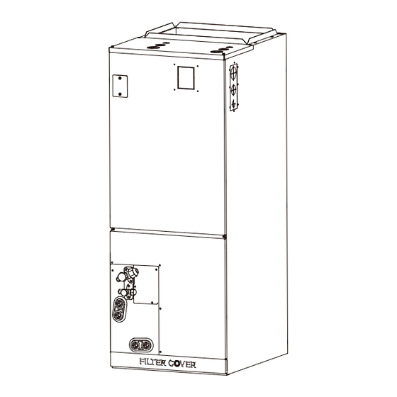
Summary of Contents for ComfortStar AHU18-SG2
-
Page 3: Read This Manual
INSTALLATION MANUAL SAFETY PRECAUTIONS ACCESSORIES INDOOR UNIT INSTALLATION REFRIGERANT PIPING CONNECTION INSTALLATION OF ELECTRIC AUXILIARY HEAT MODULE (ONLY FOR HEAT FUNCTION MODELS) CONFIRMATION OF INDOOR UNIT OUTDOOR UNIT INSTALLATION WIRING SPECIFICATION AIR EVACUATION NOTE ON ADDING REFRIGERANT TEST RUN Read this manual Inside you’ll find many helpful hints on how to use and maintain your air conditioner properly. -
Page 4: Safety Precautions
SAFETY PRECAUTIONS Intended Use The following safety guidelines are intended to prevent unforeseen risks or damage from unsafe or incorrect operation of the appliance. Please check the packaging and appliance on arrival to make sure everything is intact to ensure safe operation. If you find any damage, please contact the retailer or dealer. - Page 5 WARNINGS FOR PRODUCT USE • If an abnormal situation arises (like a burning smell), immediately turn o the unit and disconnect the power. Call your dealer for instructions to avoid electric shock, fire or injury. • Do not insert fingers, rods or other objects into the air inlet or outlet. This may cause injury, since the fan may be rotating at high speeds.
- Page 6 • If connecting power to fixed wiring, an all-pole disconnection device which has at least 3mm clearances in all poles, and have a leakage current that may exceed 10mA, the residual current device(RCD) having a rated residual operating current not exceeding 30mA, and disconnection must be incorporated in the fixed wiring in accordance with the wiring rules.
- Page 7 NOTE ABOUT FUSE SPECIFICATIONS • The air conditioner’s circuit board (PCB) may be designed with a fuse to provide overcurrent protection. This fuse must be replaces with identical component. • The specifications of the fuse, if equipped, are printed on the circuit board, examples of such are T5A/250VAC and T10A/250VAC.
- Page 8 ACCESSORIES The air conditioning system comes with the following accessories. Use all of the installation parts and accessories to install the air conditioner. Improper installation may result in water leakage, electrical shock and fire, or equipment failure. Accessories (Packed with the indoor unit) Manual Remote controller Battery...
-
Page 9: Indoor Unit Installation
INDOOR UNIT INSTALLATION CAUTION Install the indoor and outdoor units, cables and wires at least 1m (3-1/5′) from televisions or radios to prevent static or image distortion. Depending on the appliances, a 1m (3-1/5′) distance may not be su cient. The Indoor unit must be electrically grounded per national and local electrical code. -
Page 10: Horizontal Installations
WARNING There must be an airtight seal between the bottom of the air handler and the return air plenum. Use fiberglass sealing strips, foil duct tape, caulking, or equivalent sealing method between the plenum and the air handler cabinet to ensure a tight seal. Return air must not be drawn from a room where this air handler or any gas-fueled appliance (i.e., water heater), or carbon monoxide-producing device (i.e., wood fireplace) is installed. - Page 11 Indoor unit parts installation size (unit: mm/inch) Model A Model B Model(Btu/h) Model(Btu/h) 12K~24K 30K~48K Dimensions Dimensions 1143 1245 1346 1245 Length of A Length of A inch inch Length of B Length of B inch inch Length of C Length of C inch 17-1/2...
-
Page 12: Installation Position Requirements
Installation Position Requirements Vertical installations Horizontal installations NOTICE FOR DUCT CONNECTIONS: It should be assembled It should be insulated It should be Flexible It should be fabricated accordance to the and use a Vapor Barrier. suspension mounted and installed in and not fastened instructions. - Page 13 CAUTION A field-fabricated secondary drain pan, with a drain pipe to the outside of the building, is required in all installations over a finished living space or in any area that may be damaged by overflow from the main drain pan. In some localities, local codes may require a secondary drain pan for any horizontal installation.
-
Page 14: Horizontal Right Installation
Connecting the wire and pipes(pipes and drainage pipes) Vertical down Horizontal right Please follow these steps to perform installation and installation: Step 1 Open the upper cover. Step 2 Open the cover of the electronic control box. Step 3 Connect the wire according to the wiring diagram. Step 4 Connect the pipes and install the drainage pipes. - Page 15 Step 4 Step 5 Indication of the position of each Unplug temperature sensors T1, T2, T2A, T2B and temperature sensor of the evaporator: electronic expansion valve (EEV) from the control board. T1: Room temperature sensor T2: Evaporator central sensor plug T2A: Evaporator intput sensor plug 18-24K model T2B: Evaporator output sensor plug...
- Page 16 Step 6 Step 9 Take out the evaporator and drain pan and rotate 180° Reinstall T1, T2, T2A, T2B sensor plugs and electronic expansion valve (EEV) and tie up (when your equipment need to be vertical the sensor wires. downed configuration). Cut the foam gasket.
- Page 17 Step 10 The evaporator is assembled in place. Step 11 Step 13 Use cable ties to fix the room temperature sensor as shown in the figure. Connect the wire according to the wiring diagram. Step 14 cable ties Reassenble the upper cover and Reinstall the filter, filter cover plate.
-
Page 18: Vertical Discharge
NOTICE ON PURCHASING PIPES Installation requires pvc pipe or other suitable material per local and national codes, which can be obtained at your local hardware store or dealer. WARNING • After removal of drain pan plug(s), check drain hole(s) to verify that drain opening is fully open and free of any debris. -
Page 19: Refrigerant Piping Connection
REFRIGERANT PIPING CONNECTION WARNING All field piping must be completed by a licensed technician and must comply with the local and national regulations. • When the air conditioner is installed in a small room, measures must be taken to prevent the refrigerant concentration in the room from exceeding the safety limit in the event of refrigerant leakage. -
Page 20: Connection Instructions-Refrigerant Piping
Connection Instructions—Refrigerant Piping CAUTION • Insulate both the gas and liquid piping to prevent condensation. Outdoor Unit Air Handler Air Handler Unit Adapter Required at Air Outdoor Adapter Required at Outdoor Connection Unit Model Connection(in.flare) Handler Unit(in.flare to braze) Model Unit(in.flare to flare or braze) (in.flare) Liquid... -
Page 21: Step 4: Connect Pipes
Outdoor unit Liquid side piping (Smaller diameter) • Clamp flare from on the end of the pipe. The end of the pipe must extend beyond the flare form. (Bigger Flare form Pipe • Place flaring tool onto the form. Torque wrench •... - Page 22 CAUTION • Thread this pipeline through the wall and connect it to the outdoor unit. Check to make sure there is no refrigerant • Insulate all the piping, including the valves of leak after completing the installation work. the outdoor unit. If there is a refrigerant leak, ventilate the area Open the stop valves of the outdoor unit to •...
- Page 23 INSTALLATION OF ELECTRIC AUXILIARY HEAT MODULE (ONLY FOR HEAT FUNCTION MODELS) NOTICE Installation must be performed by an licensed contractor. Please make necessary precaution when performing the installation operation. Accessories Preparations for Installation Before installation, please confirm the electric Name Quantity Name Quantity...
- Page 24 Step 3 Step 5 Remove the terminal block and power wires, Tighten the mounting screws. loosen the screws, and remove the electric auxiliary heating cover. screws. Step 6 Wire according to the wiring nameplate. Step 4 Apply the wiring diagram to the inside cover wiring is completed for future reference and Install the electric auxiliary heating assembly maintenance.
- Page 25 CONFIRMATION OF INDOOR UNIT NOTICE Electric auxiliary heating wiring diagram packed with the accessories. If branch circuit wire lenght exceeds 100 ft, consult NEC 210-19a to determine maximum wire length. Use 2% voltage drop. After the electric heating wiring is connected, please confirm before power on: •...
- Page 27 Electric auxiliary heating wiring diagram...
- Page 28 Electric auxiliary heating wiring diagram...
-
Page 29: Outdoor Unit Installation
OUTDOOR UNIT INSTALLATION NOTICE Install the unit by following local switchs and regulations , there may be di er slightly between di erent regions. Select the installation location of outdoor units Before installing the outdoor unit, you must choose an appropriate location. The following are standards that will help you choose an appropriate location for the unit. - Page 30 Install drain fitting(Heat pump unit only) Base pan hole of outdoor unit Step 1: Find out the base pan hole of outdoor unit. Seal Step 2: Fit the rubber seal on the end of the drain fitting that will connect to the ●...
-
Page 31: Anchor Outdoor Unit
Anchor outdoor unit The outdoor unit can be anchored to the ground or to a wall-mounted bracket with bolt(M10). Prepare the installation base of the unit according to the dimensions below. Outdoor Unit Types and Specifications Front view Top view Outdoor Unit Dimensions Mounting Dimensions inch... - Page 32 If you will install the unit on the ground If you will install the unit on a wall-mounted bracket, or on a concrete mounting platform, DO THE FOLLOWING: DO THE FOLLOWING: Mark the positions for four expansion bolts Mark the position of bracket holes based on ●...
-
Page 33: Wiring Precautions
WIRING PRECAUTIONS WARNING BEFORE PERFORMING ANY ELECTRICAL WORK, READ THESE WARNINGS. All wiring must comply with local and national Do not let wires touch or rest against ● ● electrical codes, regulations and must be installed refrigerant tubing, the compressor, or any by a licensed electrician. -
Page 34: Outdoor Unit Wiring
OUTDOOR UNIT WIRING WARNING Before performing any electrical or wiring work, turn o the main power to the system. Step 1: Prepare the cable for connection. 1. You must first choose the right cable size. 2. Using wire strippers, strip the rubber CLASS 2 jacketfrom both ends of the signal cable to B W D... -
Page 35: Indoor Unit Wiring
INDOOR UNIT WIRING CAUTION • While connecting the wires, please strictly follow the wiring diagram. • The refrigerant circuit can become very hot. Keep the interconnection cable away from the copper tube. Step 1: Prepare the cable for connection. WARNING Using wire strippers, strip the insulating jacket from both ends of the signal cable to reveal ISOLATE THE POWER SUPPLY LEADS... - Page 36 SPECIFIC WIRING METHODS WARNING Please refer to the wiring nameplate for the wiring method. Do not connect the power cord to the communication line, as this may damage the system. Connection method A: Connection method B: Refer to the wiring method of internal and To use a 24V thermostat, you need to refer to the external machine communication and wired following wiring:...
- Page 37 S4-2 Default on, DH function o . S4-1 Default on, W1 and W2 Turn switch o to activate DH shorted for single stage Aux heat function. operation. Turn o to separate stages. S4-2 Default on, DH function o . S4-1 Default on, W1 and W2 Turn switch o to activate DH shorted for single stage Aux heat function.
-
Page 38: Alarm Output
The fault warning: Optional function wiring: Alarm output: An alarm output (CN33) can be utilized if actions are required when a fault is present. This is a passive outlet port, so you will need to input a voltage signal. The relay is normally-open for normal operation, and closed when a fault condition is active. -
Page 39: Led Display
Dehumidification control wiring Control logic Indoor unit connector Connector Purpose Dehumidification control requires external Humidistat at DH and R. Set S4-2 as OFF. When the humidity rises and exceeds the set value of the Humidistat, the 24V signal of DH changes to 0V, the cooling system starts the dehumidification operation, and the air volume drops to 80% of the nominal cooling air volume. - Page 40 DIP switch definitions Function Rotary switch...
- Page 41 Function DIP switch settings: Function combination table of SW1-1 and SW1-4: The 24V thermostat mode needs to refer Control type Stand alone or full system to the following settings: Free match Free match Wired Full system controller Full system Thermostat 000 is the default 000/001/010/ 011/100/101/110/111,internal machines with di erent abilities,...
- Page 42 Table A 24V Tstat, S1+S2 S3 ( S3 ( Control Scenario Wired Controller S1+S2 Full 24V Outdoor unit DIP Switch setting Metering device location Address DIP switch: Determined by dial code S2 1-10K 2-5.1K Address dialing S1+S2: When the user uses the Dial code selection Website address centralized controller, the address dialing is...
- Page 43 Air volume table 24V thermostat Wired controller Air ow External Static volume Capacity Fan speed Electric heater kit Pressure Range DIP Switch 24V terminal engaged DIP Switch Mode (CFM) Cooling Turbo — SW3-4=ON Y2/Y — Cool Cooling High — SW3-4=OFF Y2/Y —...
- Page 44 Air volume table 24V thermostat Wired controller Air ow fl External Static volume Capacity Fan Speed Electric heater kit Pressure Range DIP Switch 24V terminal engaged DIP Switch Mode (CFM) — SW3-4=ON Y2/Y — Cool Cooling Turbo 1188 — SW3-4=OFF Y2/Y —...
-
Page 45: Power Specifications
POWER SPECIFICATIONS Cooling and Heating power specifications PHASE POWER (outdoor) FREQUENCY AND VOLT Hyper HT Hyper HT Hyper HT OUTDOOR UNIT(A) INPUT CIRCUIT FUSE / 16 / 20 / 23 MOCP 20 / 30 / 35 / 2+Ground LINE QUANTITY OUTDOOR UNIT POWER LINE LINE DIAMETER(AWG) -
Page 46: Air Evacuation
AIR EVACUATION NOTICE When opening valve stems, turn the hexagonal wrench until it hits against the stopper. Do not try to force the valve to open further. Close the Low Pressure side of the manifold Preparations and precautions gauge, and turn o the vacuum pump. Wait for 5 minutes, then check that there Air and foreign matter in the refrigerant circuit has been no change in system pressure. -
Page 47: Note On Adding Refrigerant
NOTE ON ADDING REFRIGERANT CAUTION DO NOT mix refrigerant types. Some systems require additional charging depending on pipe lengths. The standard pipe length varies according to local regulations. For example, in North America, the standard pipe length is 7.5m (25’). In other areas, the standard pipe length is 5m (16‘). -
Page 48: Before Test Run
TEST RUN CAUTION Failure to perform the test run may result in unit damage, property damage, or personal injury. 5. For the Outdoor Unit Before test run a. Check to see if the refrigeration system is leaking. A test run must be performed after the entire b. - Page 49 24V SIGNAL CHART 24V input terminal Mode Priority Y/Y2 E/AUX DH/DS/BK Fan speed Display Cooling stage 1 Cooling stage 2 High Dehumidification Dehumidification Heat pump stage 1 Heat pump stage 2 High Heat pump stage 2 High Electric heater kit 1 Turbo Electric heater kit 2 Turbo...
- Page 50 The design and specifications are subject to change without prior notice for product improvement. Consult with the sales agency or manufacturer for details. Any updates to the manual will be uploaded to the service website, please check for the latest version.
- Page 52 QS001I-AHU(24V)
Need help?
Do you have a question about the AHU18-SG2 and is the answer not in the manual?
Questions and answers