Table of Contents
Advertisement
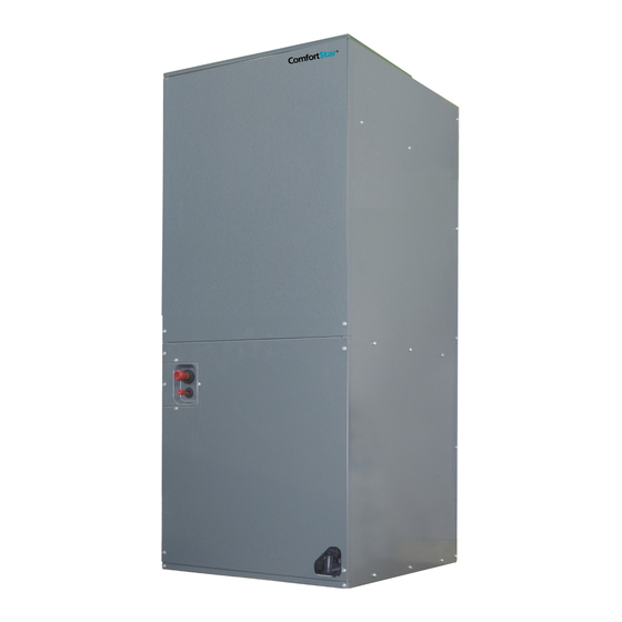
SPLIT AIR CONDITIONERS
Service Manual
Comfort
BAR4&LUC4
IMPORTANT NOTE:
Read this manual carefully before operating your
new air conditioning unit. Make sue to save this
manual for future reference.
Please check the applicable models, technical data,
F-GAS(if any) and manufacturer information from the "Owner's
Manual - Product Fiche " in the packaging of the outdoor unit.
(European Union products only)
Sta
恁)
且』
Advertisement
Table of Contents

Related Manuals for ComfortStar BAR4


Summary of Contents for ComfortStar BAR4
- Page 1 SPLIT AIR CONDITIONERS Service Manual Comfort 恁) BAR4&LUC4 且』 IMPORTANT NOTE: Read this manual carefully before operating your new air conditioning unit. Make sue to save this manual for future reference. Please check the applicable models, technical data, F-GAS(if any) and manufacturer information from the "Owner's Manual - Product Fiche "...
-
Page 3: Table Of Contents
CONTENT P art 1. G en eral In fo rm atio n ......................1 1. Nomenclature ........................2 2. Model Names of Indoor/Outdoor Units ................2 3. E x t e r n a l A p p e a r a n c e ..................3 4. -
Page 4: P Art 1. G En Eral In Fo Rm Atio N
P a rt 1 . G e n e ra l In fo rm a tio n 1.Nomenclature................2 2.Model names of Indoor/Outdoor unit......2 3.External Appearance............3 4.Features..............4... -
Page 5: Nomenclature
D im en sio n (W × H × D ) (in ch ) P o w er su p p ly 15 S E E R C o o lin g O n ly & H ea t P u m p BAR4-18-15 21-4/5x25x21-4/5 208/230V-1Ph-60Hz... -
Page 6: E X T E R N A L A P P E A R A N C E
3. E xte rn al A p p earan ce 3.1 In d o o r u n it 3.2 O u td o o r u n it N o te: S tan d ard o u td o o r u n it is u sin g p lastic g rill. M etal g rill can b e cu sto m ized . General Information... -
Page 7: Features
4. F e atu res 4.1 O p eratio n featu res Long Piping & Cost Effective Low noise operation, as low as 42dB(A) 24V control, time delay relay, fan relay and transformer included. 4.2 P erfo rm an ce featu res ... -
Page 8: P Art 2. In D O O R U N It
P a rt 2 . In d o o r U n it 1.Features ....................2 2.Dimension ...................4 3.Service Space ..................5 4.Wiring Diagrams ..................7 5.Electric Characteristics ................8 6.The Specification of Wiring ..............8 7. Field Wiring ..................8... -
Page 9: Features
1. F ea tu re s (1) “A” shape coils, constructed with copper tubing and enhanced aluminum fins. (2) ECM motors, the air handler has multiple fan modes to choose from, which can flexibly respond to various environments. (3) φ12″large fan blade that has powerful fan speed, and the motor is covered with insulation material, which can ensure that the motor runs in a safe state. - Page 10 (6) Electric Heating with Different Power (Optional) SPEC. For 15 SEER AHU Electrical Heater SPEC. Part No. Model 5 kw 8024325A0001 7.5 kw 8024325A0002 18/24/30/36/42/48/60 K 10 kw 8024325A0003 15 kw 8024325A0004 36/42/48/60 K 20 kw 8024325A0005 48/60 K (7) Multi-position installation (Optional) Versatile 4-way convertible design for vertical up airflow, vertical down airflow*, horizontal left airflow* and horizontal right airflow.
-
Page 11: Dimension
2. D im e n s io n Indoor Unit... -
Page 12: Service Space
3. Service Space The indoor unit should be installed in a location that meets the following requirements: INSTALLATION NOTES: 1. For vertical upward airflow (Standard), the position and dimension of rubber plugs and traps of drain pipes are as follows: 2. - Page 13 3. For horizontal right airflow (Standard), the position and dimension of seal plugs of drain pipes are as follows: 4. For horizontal left airflow (Optional), the position and dimension of seal plugs of drain pipes are as follows: # R e m ark : P le a s e re fe r to th e in s talla tio n m a n u a l fo r m o re in s ta lla tio n in fo rm a tio n . 5.
-
Page 14: Wiring Diagrams
4. W iring Diagram s 18K /24K /30K /36K /42K /48K /60K Indoor Unit... -
Page 15: Electric Characteristics
5. Electric Characteristics 6 . E le c t r ic a l W ir in g N o te : The diameters of wires or lines should not be less than the corresponding ones listed in the table below; Besides, if the power wires is quite long from the unit, please choose the winding with larger cross-section area to guarantee the normal power supply. -
Page 16: P Art 3 O U Td O O R U N It
P a rt 3 O u td o o r U n it 1. Dimensions ..................2 2. Service Space .................. 3 3. Wiring Diagrams ................4 4. Electric Characteristics ..............5 5. Operation Limits ................6 6. Sound Levels ................... 6 7. -
Page 17: Dimension
1. Dimension When installing the outdoor unit on the roof, make sure that the roof can support the weight of the outdoor unit. It is recommended to choose appropriate isolation to prevent sound or vibration from being transmitted to the building structure. Outdoor Unit... -
Page 18: Service Space
2. Service Space 1. Make sure that the discharge area at least 60 inches above the top of the unit is unrestricted. 2. The clearance from one side of the access panel to the wall should be at least 24 inches. 3. -
Page 19: Wiring Diagrams
3 . W ir in g D ia g r a m s C o o lin g o n ly Outdoor Unit... -
Page 20: Electric Characteristics
O u td o o r U n it (S cro ll) M o d el M IN . C ircu it V o ltag e M in . M ax. M axi F u se A m p acity BAR4-18-15 BAR4-24-15 BAR4-30-15 BAR4-36-15 208/230V 187V 253V BAR4-42-15... -
Page 21: Operation Limits
5 . Op era tio n L im its Operation mode Outdoor temperature (℉) Cooling operation 65~115 Heating operation 5~86 6 . S o u n d L e v e ls Microphone (body height +1 )/2 m M o d el N o ise level d B (A ) N o te : S o u n d le v e l is m e a s u re d a t a p o in t 1 m in fron t o f th e u n it, a t a h e ig h t o f (U n it b o d y h e ig h t + 1 )/2 m . -
Page 22: Refrigerate Diagram
7. Refrigerate diagram A p p licab le fo r co o lin g o n ly typ e A p p licab le fo r h eat p u m p typ e N o te : In h e a tin g m o d e , th e th ro ttlin g d e v ic e is o u td o o r u n it p is to n ; In c o o lin g m o d e , th e thro ttle d e v ic e is in d o o r u n it p is to n . -
Page 23: P Art 4 In Stallatio N
P a rt 4 In s ta lla tio n 1 .Precaution on Installation ..............2 2. Emptying ..................4 3. Additional Refrigerant Charge ............4 4. Insulation Work ................5... -
Page 24: Precaution On Installation
1 . P reca u tio n o n In s talla tio n 1.1 M easu re th e n ecessary len g th o f th e co n n ectin g p ip e, an d m ake it b y th e fo llo w in g w ay a. - Page 25 1.4 R efrig eran t P ip elin e L eakag e In sp ectio n a. Use dry nitrogen to pressurize the refrigerant line and evaporator coil to 150 PSIG. b. Use soapy water or foam at each soldering position to check for leaks. 1.5 T h en , o p en th e stem o f sto p valu es o f th e o u td o o r u n it to m ake th e refrig eran t p ip e co n n ec tin g th e in d o o r u n it w ith th e o u td o o r u n it in flu en t flo w .
-
Page 26: Emptying
2 . E m p tyin g C A U T IO N S : Do not open the service valve until the leakage inspection and emptying of refrigerant lines and indoor coils are completed. 1. Evacuate until the micrometer reading is not higher than 350 micrometers, and then close the valve of the vacuum pump. -
Page 27: Insulation Work
4 . In su la tio n W o rk 4.1 In su latio n m aterial an d th ickn ess 1. Insulation material Insulation material should adopt the material which is able to endure the pipe’s temperature: no less than 70℃... - Page 28 For construction convenience, before laying pipes, use insulation material to insulate the pipes to be deal with, at the same time, at two ends of the pipe, remain some length not to be insulated, in order to be welded and check the leakage after laying the pipes.
-
Page 29: P Art 5 U N It M Ain Ten An Ce
P a rt 5 U n it m a in te n a n c e 1. Fault indicator of indoor unit ............. 2 2. Fault indicator of outdoor unit ............2 3. Troubleshooting of Fault Codes ............3... -
Page 30: Fault Indicator Of Indoor Unit
1 . F au lt in d ica to r o f in d o o r u n it The meaning of the fault indicator: C o n ten t Description Unit is standby Green light flash 1 time every 3 seconds Normal display Unit is running normally Green light ON... -
Page 31: Troubleshooting Of Fault Codes
3 . Tro u b les h o o tin g o f F au lt C o d e s 3.1 T3 Condenser Temperature sensor error 3.2 T4 Outdoor Ambient Temperature sensor error Unit maintenance... - Page 32 3.3 T5 Discharge Temperature sensor error 3.4 Low Pressure alarm Unit maintenance...
- Page 33 3.5 High Pressure alarm 3.6 T3 high temperature protection Unit maintenance...
- Page 34 3.7 T5 high temperature protection 3.8 Fan motor feedback error Unit maintenance...
Need help?
Do you have a question about the BAR4 and is the answer not in the manual?
Questions and answers