Table of Contents
Advertisement
Quick Links
Advertisement
Table of Contents

Related Manuals for Applied Motion Products SSDC Series


Summary of Contents for Applied Motion Products SSDC Series
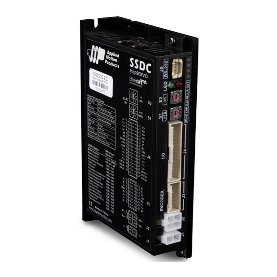
- Page 1 SSDC03/06/10-EC StepSERVO EtherCAT Drive Hardware Manual 920-0149B 11/3/2019...
-
Page 2: Table Of Contents
6.1 Drive Mechanical Outlines ..................41 6.2 Technical Specifications ..................42 6.3 Recommended Motors ...................43 6.4 Mechanical Dimension ..................44 6.5 Torque Curves ......................47 7 Accessories ......................49 7.1 Standard Accessories (Included) ................49 7.2 Optional Accessories (Sold Separately) ..............49 8 Contacting Applied Motion Products ..............52 920-0149B 11/3/2019... -
Page 3: Introduction
SSDC-EC Hardware Manual 1 Introduction Thank you for selecting the Applied Motion Products SSDC series StepSERVO drive and motor. SSDC series combines servo technology with a stepper motor to create a product with exceptional feature and broad capability. The SSDC series is a high performance, intelligent StepSERVO system with multi-axes field bus control. -
Page 4: Block Diagram
SSDC-EC Hardware Manual 1.2 Block Diagram SSDC EtherCAT Block Diagram Power Supply: Filter SSDC06/10: 24-70VDC SSDC03: 12-48VDC Internal DC Input Voltage Logic Power Temp. Supply Converter Det. High Speed Input Mosfet Digital Software Optical Filter Filter Ioslation Power Amplifier Over Current Input Det. -
Page 5: Safety Instructions
Equipment damage or serious injury to personnel can result from the failure to follow all applicable codes and standards. Applied Motion Products does not guarantee the products described in this publication are suitable for a particular application, nor do they assume any responsibility for product design, installation, or operation. -
Page 6: Getting Started
• A PC running Microsoft Windows XP/Vista/7/8/10 (Using serial communication port. Prepare an USB to Serial converter if the PC doesn’t have it. • Install the StepSERVO Quick Tuner software (download from Applied Motion Products website: www.applied-motion.com ) • A power cable(included) • Included a RS232 configuration cable used to configure the drive. -
Page 7: Installing Software
• Download the StepSERVO Quick Tuner from the Applied Motion Products website and install it. • Launch the software by clicking Start-----Programs ----Applied Motion Products connect the drive to PC by RS232 communication cable, configure the communication port on PC. Please see the section below entitled “Connecting the Drive using RS-232”. -
Page 8: Choosing The Right Com Port
SSDC-EC Hardware Manual 2.2 Connecting to the PC using RS-232 Connector J5 is RS-232 communication port, please use the included RS-232 cable to connect the drive and PC. Use the StepSERVO Quick Tuner software to configure the drive parameter, tuning, monitoring the status of drive and motor. Definition DGND 2.3 Choosing the Right COM Port... -
Page 9: Connecting The Ethercat
SSDC-EC Hardware Manual 2.4 Connecting the EtherCAT Dual RJ-45 connectors accept standard Ethernet cables and are categorized as 100BASE-TX(100 Mb/sec) ports. CAT5 or CAT5e (or higher) cables should be used. The IN port connects to a master, or to the OUT port of an upstream node. The OUT port connects to a downstream node. - Page 10 SSDC-EC Hardware Manual 2.5 Setting the EtherCAT Node ID SSDC-EC support three methods to set and read the EtherCAT Node ID(Alias ID): ×10 MSD ×1 LSD EtherCAT ID 2.5.1 Set by rotary switches When the drive’s ID is configured to be set by rotary switches in Step-Servo Quick Tuner software, two decimal rotary switches on the drive are used to set a nonzero value (range 1~99) as the EtherCAT node Alias ID.
-
Page 11: Connecting The Power Supply
2.6 Connecting the Power Supply The SSDC series StepSERVO drive and motor are shipped with a power cable, 2 meters long. Connect the red wire to the positive of the power supply. Connect the black wire to the negative of the power supply. Plug the cable into the power connector of the drive. -
Page 12: Choosing A Power Supply
SSDC-EC Hardware Manual 2.7 Choosing a Power Supply The main considerations when choosing a power supply are the voltage and current requirements for the application. 2.7.1 Voltage The SSDC drive is designed to give optimum performance between 24 and 48 Volts DC. Choosing the voltage depends on the performance needed and motor/drive heating that is acceptable and/or does not cause a drive over-temperature. - Page 13 SSDC-EC Hardware Manual 2.7.2 Supply Current The maximum supply currents required by the SSDC are shown in the charts below at different power supply voltage inputs. The SSDC power supply current is lower than the winding currents because it uses switching amplifiers to convert a high voltage and low current into lower voltage and higher current.
- Page 14 SSDC-EC Hardware Manual HT17-SS 1 DG_ 24V Power Torque Continuous Boost Supply Current Full Load No Load Speed(RPS) HT17-SS 1 DG_ 48V Power Torque Continuous Boost Supply Current Full Load No Load Speed(RPS) HT17-SS2DG_ 24V Power Torque Continuous Boost Supply Current Full Load No Load Speed(RPS)
- Page 15 SSDC-EC Hardware Manual HT17-SS2DG_ 48V Power Torque Continuous Boost Supply Current Full Load No Load Speed(RPS) HT17-SS 3 DG_ 24V Power Torque Continuous Boost Supply Current Full Load No Load Speed(RPS) HT17-SS3DG_ 48V Power Torque Continuous Boost Supply Current Full Load No Load Speed(RPS) 920-0149B...
- Page 16 SSDC-EC Hardware Manual HT17-SS 4 DG_ 24V Power Torque Continuous Boost Supply Current Full Load No Load Speed(RPS) HT17-SS4DG_ 48V Power Torque Continuous Boost Supply Current Full Load No Load Speed(RPS) HT23-SS2DG_ 24V Power Torque Continuous Boost Supply Current Full Load No Load Speed(RPS) 920-0149B...
- Page 17 SSDC-EC Hardware Manual HT23-SS2DG_ 48V Power Torque Continuous Boost Supply Current Full Load No Load Speed(RPS) HT23-SS2DG_ 70V Power Torque Continuous Boost Supply Current Full Load No Load Speed(RPS) HT23-SS3DG_ 24V Power Torque Continuous Boost Supply Current Full Load No Load Speed(RPS) 920-0149B 11/3/2019...
- Page 18 SSDC-EC Hardware Manual HT23-SS3DG_ 48V Power Torque Continuous Boost Supply Current Full Load No Load Speed(RPS) HT23-SS3DG_ 70V Power Torque Continuous Boost Supply Current Full Load No Load Speed(RPS) HT23-SS4DG_ 24V Power Torque Continuous Boost Supply Current Full Load No Load Speed(RPS) 920-0149B 11/3/2019...
- Page 19 SSDC-EC Hardware Manual HT23-SS4DG_ 48V Power Torque Continuous Boost Supply Current Full Load No Load Speed(RPS) HT23-SS4DG_ 70V Power Torque Continuous Boost Supply Current Full Load No Load Speed(RPS) HT24-SS3DG_ 24V Power Torque Continuous Boost Supply Current Full Load No Load Speed(RPS) 920-0149B 11/3/2019...
- Page 20 SSDC-EC Hardware Manual HT24-SS3DG_ 48V Power Torque Continuous Boost Supply Current Full Load No Load Speed(RPS) HT24-SS3DG_ 70V Power Torque Continuous Boost Supply Current Full Load No Load Speed(RPS) HT34-SS1DG_ 24V Power Torque Continuous Boost Supply Current Full Load No Load Speed(RPS) 920-0149B 11/3/2019...
- Page 21 SSDC-EC Hardware Manual HT34-SS1DG_ 48V Power Torque Continuous Boost Supply Current Full Load No Load Speed(RPS) HT34-SS1DG_ 70V Power Torque Continuous Boost Supply Current Full Load No Load Speed(RPS) HT34-SS3DG_ 24V Power Torque Continuous Boost Supply Current Full Load No Load Speed(RPS) 920-0149B 11/3/2019...
- Page 22 SSDC-EC Hardware Manual HT34-SS3DG_ 48V Power Torque Continuous Boost Supply Current Full Load No Load Speed(RPS) HT34-SS3DG_ 70V Power Torque Continuous Boost Supply Current Full Load No Load Speed(RPS) HT34-SS5DG_ 24V Power Torque Continuous Boost Supply Current Full Load No Load Speed(RPS) 920-0149B 11/3/2019...
- Page 23 SSDC-EC Hardware Manual HT34-SS5DG_ 48V Power Torque Continuous Boost Supply Current Full Load No Load Speed(RPS) HT34-SS5DG_ 70V Power Torque Continuous Boost Supply Current Full Load No Load Speed(RPS) 920-0149B 11/3/2019...
-
Page 24: Connecting The Motor
SSDC-EC Hardware Manual 2.9 Connecting the Motor The StepSERVO motors have two cables. One is the motor power cable, the other one is the encoder feedback cable. Plug the motor power cable into the motor connector on the drive and plug the encoder feedback cable into the encoder feedback connector on the drive. -
Page 25: Inputs And Outputs
SSDC-EC Hardware Manual 3 Inputs and Outputs SSDC inputs and outputs include • 8 optically isolated digital inputs,5 - 24VDC logic • 4 Optically isolated, Open Collector, 30V/100 mA max, • 2 analog inputs can be configured to 0-5V, 0-10V, ±5V or ±10V signal ranges •... -
Page 26: Digital Inputs
SSDC-EC Hardware Manual 3.1 Digital Inputs 3.1.1 X1, X2, X3 and X4 Digital Inputs X1, X2: Optically isolated, differential, 5-24VDC; Minimum pulse width = 250ns, Maximum pulse frequency = 2MHz; X3, X4: Optically isolated, differential, 5-24VDC; Minimum pulse width = 100μs, Maximum pulse frequency = 5KHz X1 can be configured as general purpose input X2 can be configured as general purpose input X3 can be configured as CW limit sensor input or general purpose input... - Page 27 SSDC-EC Hardware Manual 3.1.2 X5, X6, X7 and X8 Digital Inputs X5 ~ X8: Optically isolated, differential, 5-24VDC; Minimum pulse width = 100μs, Maximum pulse frequency = 5KHz; X5 can be configured as servo on input or general purpose input X6 can be configured as alarm reset signal input or general purpose input X7 can be configured as Touch Probe 1 trigger input or general purpose input X8 can be configured as Touch Probe 2 trigger input or general purpose input...
-
Page 28: Digital Outputs
SSDC-EC Hardware Manual 3.2 Digital Outputs Y1, Y2, Y3 and Y4 Digital Outputs Y1 can be configured as alarm signal output. It can also be configured as static in position signal output(static, checking in position when motor is stopped) ,or as dynamic in position signal output (dynamic, checking in position all the time.) Y2 can be configured as Tach signal output, tach output produce pulsed relative to the motor position with configurable resolution. - Page 29 SSDC-EC Hardware Manual 5 - 24V Power Supply – Load Y1/2/3/4+ SSDC Y1/2/3/4- Connecting a sourcing output to load 5 - 24V Power Supply – Y1/2/3/4+ SSDC Y1/2/3/4- Connecting a sinking output to PLC's input 5 - 24V Power Supply –...
-
Page 30: Analog Inputs
3.3 Analog Inputs SSDC series drive has two analog signal inputs which can accept signal range of 0-5V, 0-10V, ±5V and ±10V. The drive can be configured to operate at velocity mode or position mode that is proportional to the analog input. -
Page 31: Secondary Encoder Input
3.5 Secondary Encoder Input SSDC series supports secondary encoder feedback, you can connect to the load side position feedback such as linear encoder on your drive encoder inputs. Connect the ENC A+/-,ENC B+/-,ENC Z+/-, the secondary encoder input can be accepted both of single-ended and differential signal. -
Page 32: Mounting The Drive
4 Mounting the Drive Use the M3 or M4 screw to mount the SSDC series drive. The Drive should be securely fastened to a smooth, flat metal surface will help conduct heat away from the chassis. If this is not possible, forced airflow from a fan maybe required to prevent the drive from overheating. -
Page 33: Reference Materials
SSDC-EC Hardware Manual 6 Reference Materials 6.1 Drive Mechanical Outlines (Unit:mm) 920-0149B 11/3/2019... -
Page 34: Technical Specifications
SSDC-EC Hardware Manual 6.2 Technical Specifications Power Amplifier Amplifier Type Dual H-Bridge, 4 Quadrant Current Control 4 state PWM at 20 KHz SSDC03: Continuous Current 3A max, Boost Current 4A max (1.5s), current limitation auto set-up by attached motor SSDC06: Output Current Continuous Current 6A max, Boost Current 7.5A max (1.5s), current limitation auto set-up by attached motor SSDC10:... -
Page 35: Recommended Motors
SSDC-EC Hardware Manual 6.3 Recommended Motors Permissible Shaft Load (N) Holding Rotor Encoder Max. Frame Mass Motor Part Matching Permissible Torque Inertia Resolution Speed Size Distance (L) from shaft end (mm) Number Drive Thrust Load G-cm counts/rev HT11-SS1DMA 0.065 HT11-SS2DMA SSDC03 0.08 4096... -
Page 36: Mechanical Dimension
SSDC-EC Hardware Manual 6.4 Mechanical Dimension HT11-SS (Unit: mm) HT17-SS (Unit: mm) 920-0149B 11/3/2019... - Page 37 SSDC-EC Hardware Manual HT23-SS (Unit: mm) HT24-SS (Unit: mm) HT34-SS (Unit: mm) 920-0149B 11/3/2019...
- Page 38 SSDC-EC Hardware Manual 920-0149B 11/3/2019...
-
Page 39: Torque Curves
SSDC-EC Hardware Manual 6.5 Torque Curves Continuous HT11-SS1DM_ HT11-SS2DM_ Continuous Boost Boost 14.2 21.2 11.3 12.7 Speed(rps) Speed(rps) Continuous Continuous HT11-SS3DM_ HT17-SS1DG_ Boost Boost 28.3 56.6 22.7 42.5 28.3 14.2 Speed(rps) Speed(rps) Continuous Continuous HT17-SS2DG_ HT17-SS3DG_ Boost Boost 70.8 70.8 56.6 56.6... - Page 40 SSDC-EC Hardware Manual Continuous Continuous HT23-SS4DG_ HT23-SS3DG_ Boost Boost 495.7 424.9 283.2 212.4 141.6 70.8 Speed(rps) Speed(rps) Continuous Continuous HT24-SS3DG_ HT34-SS1DG_ Boost Boost Speed(rps) Speed(rps) Continuous Continuous HT34-SS3DG_ HT34-SS5DG_ Boost Boost 1416 1133 Speed(rps) Speed(rps) 920-0149B 11/3/2019...
-
Page 41: Accessories
SSDC-EC Hardware Manual 7 Accessories 7.1 Standard Accessories (Included) • -EC Type Model Catagory Vendor Description Cable Power supply cable CAT5 Ethernet Cable 0.3m network cable Screwdriver Screwdriver 39-01-3048 Housing Molex Motor connector housing J2 501646-1600 Housing Molex Encoder connector housing J3 501646-3200 Housing Molex... - Page 42 SSDC-EC Hardware Manual 7.2.2 Extended motor cable (For SSDC drive and HT11SS motor) Housing:51065-0600(Molex) Housing: 39-01-3048(Molex) Crimp:50212-8000(Molex) Crimp: 39-00-0038(Molex) Length(L) Wiring Diagram 3004-408-1M PIN(J1) Color (Signal) 3004-408-3M Blue(B-) 3004-408-5M Red(B+) 3004-408-10M Green(A-) Black(A+) 7.2.3 Extended motor cable (For SSDC drive and HT17/23/24/34SS motor) Housing:...
- Page 43 SSDC-EC Hardware Manual 7.2.4 Extended encoder cable (For SSDC drive and HT11 motor) Housing:501646-1200(Molex) Housing: J21DF-16V-KX-L(JST) Crimp:501648-1000(Molex) Crimp: SJ2F-002GF-P1.0(JST) Length(L) Wiring Diagram 3004-339-1M PIN (J1) Color (Signal) PIN (J2) PIN (J1) Color (Signal) PIN (J2) 3004-339-3M Blue (A+) Shield 3004-339-5M Blue/Black (A-) Brown (U+) 3004-339-10M...
-
Page 44: Contacting Applied Motion Products
SSDC-EC Hardware Manual 8 Contacting Applied Motion Products 404 Westridge Dr. Watsonville, CA 95076 USA 1-800-525-1609 www.applied-motion.com 920-0149B 11/3/2019...
Need help?
Do you have a question about the SSDC Series and is the answer not in the manual?
Questions and answers