Table of Contents
Advertisement
Quick Links
Advertisement
Table of Contents

Related Manuals for Applied Motion Products TSM17 Series


Summary of Contents for Applied Motion Products TSM17 Series
- Page 1 TSM17S/Q Integrated Step-Servo Motor Hardware Manual 920-0084C 8/2/2018...
-
Page 2: Table Of Contents
5 Reference Materials ..................25 5.1 Mechanical Outlines ................25 5.2 Technical Specifications ................. 26 5.3 Torque-Speed Curves ................27 5.4 SCL Command Reference ..............28 5.5 Optional Accessories ................30 6 Contacting Applied Motion Products ..............34 920-0084C 8/2/2018... - Page 3 TSM17S/Q Hardware Manual Communications Model RS-232 RS-485 Modbus/RTU TSM17S-1AG TSM17S-1RG TSM17S-2AG TSM17S-2RG TSM17S-3AG TSM17S-3RG TSM17Q-1AG TSM17Q-1RG TSM17Q-2AG TSM17Q-2RG TSM17Q-3AG TSM17Q-3RG 920-0084C 8/2/2018...
-
Page 4: Introduction
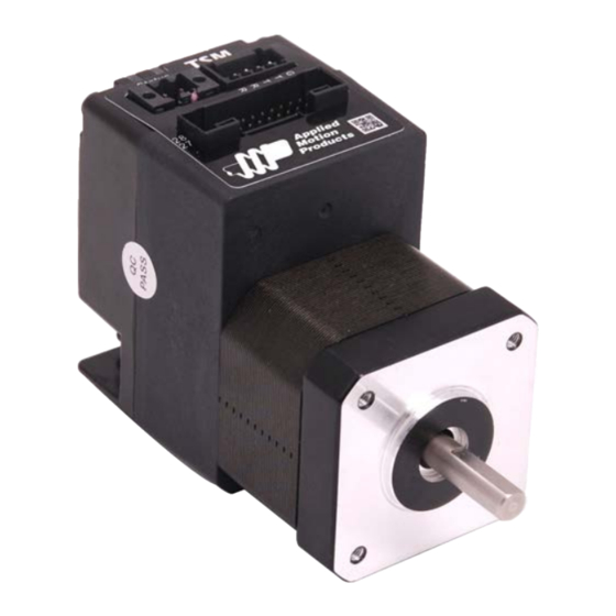
TSM17S/Q Hardware Manual 1 Introduction Thank you for selecting the Applied Motion Products TSM17S/Q Integrated Motor.The TSM line of integrated step-servo motors combines servo technology with an integrated motor to create a product with exceptional feature and broad capability. We hope our commitment to performance, quality and economy will result in a successful motion control project. -
Page 5: Block Diagram
TSM17S/Q Hardware Manual 1.2 Block Diagram TSM17S/Q Block Diagram 12 - 48 VDC External 5 Volt DC Power Supply Power Supply RS-232 RXD,+5V,TXD,GND,GND RS-232 or RS-485 RS-485 3.3VDC RX+,RX-,TX+,TX-,GND Internal Voltage Logic Temp Supply Detect +5VDC (100mA max) MOSFET motor Power Amplifier Driver... -
Page 6: Safety Instructions
Equipment damage or serious injury to personnel can result from the failure to follow all applicable codes and standards. Applied Motion Products does not guarantee the products described in this publication are suitable for a particular application, nor do they assume any responsibility for product design, installation, or operation. -
Page 7: Getting Started
Before utilizing the TSM17S/Q Integrated Step-Servo Motor and Step-Servo Quick Tuner Software in an application, the following steps are necessary: • Install the Step-Servo Quick Tuner software from the Applied Motion Products website. • Connect the drive to the PC using the programming cable. When using RS-485, it must be setup in a 4-Wire configuration (see “Connecting to a host using RS-485”... -
Page 8: Choosing A Power Supply
TSM17S/Q Hardware Manual 2.3 Choosing a Power Supply The main considerations when choosing a power supply are the voltage and current requirements for the application. 2.3.1 Voltage The TSM17S/Q is designed to give optimum performance between 24 and 48 Volts DC. Choosing the voltage depends on the performance needed and motor/drive heating that is acceptable and/ or does not cause a drive over-temperature. -
Page 9: Current
TSM17S/Q Hardware Manual 2.3.3 Current The maximum supply currents required by the TSM17S/Q are shown in the charts below at different power supply voltage inputs. The TSM17S/Q power supply current is lower than the winding currents because it uses switching amplifiers to convert a high voltage and low current into lower voltage and higher current. - Page 10 TSM17S/Q Hardware Manual □ □ TSM17 G 48V Power Torque Continuous Boost Supply Current Full Load No Load Speed(RPS) □ □ TSM17 G 12V Power Torque Continuous Boost Supply Current Full Load No Load Speed(RPS) □ □ TSM17 G 24V Power Torque Continuous Boost...
- Page 11 TSM17S/Q Hardware Manual □ □ TSM17 G 48V Power Torque Continuous Boost Supply Current Full Load No Load Speed(RPS) □ □ TSM17 G 12V Power Torque Continuous Boost Supply Current Full Load No Load Speed(RPS) □ □ TSM17 G 24V Power Torque Continuous Boost...
- Page 12 TSM17S/Q Hardware Manual □ □ TSM17 G 48V Power Torque Continuous Boost Supply Current Full Load No Load Speed(RPS) 920-0084C 8/2/2018...
-
Page 13: Installation/Connections
To Power Supply- Vout RC880 Applied Motion Products offers two matched power supplies for use with the TSM. A 24VDC, 150W(P/N PS150A24) and a 48VDC 320W(P/N PS320A48). These power supplies have current over load capability making them ideal for use. -
Page 14: Connecting The Tsm17S/Q Communications
Note: If the PC does not have an RS-232 serial port, a USB Serial Converter will be needed. You can contact Applied Motion Products to buy a USB to RS-232 converter. The RS-232 circuitry does not have any extra electrical “hardening” and care should be taken when connecting to the RS-232 port as hot plugging could result in circuit failure. -
Page 15: Connecting To A Host Using Rs-485
Some converters make this process very difficult to implement and can delay communications. NOTE: If the PC does not have an RS-485 serial port, a converter is required. You can contact Applied Motion Products to buy a USB to RS-485 converter. 120Ω to PC TX+... - Page 16 Drive #N NOTE: If the PC does not have an RS-485 serial port, a converter is required. You can contact Applied Motion Products to buy a USB to RS-485 converter. Assigning Addresses Before the entire system is wired, each drive will need to connect individually to the host computer so that it can be assigned a unique address.
-
Page 17: Inputs And Outputs
TSM17S/Q Hardware Manual 3.3 Inputs and Outputs The TSM17S/Q has three types of inputs: • High speed digital inputs for step & direction commands or encoder following, 5 to 24 volt logic • Low speed digital input for other signals, 5 to 24 volt logic •... -
Page 18: Step & Dir Digital Inputs
TSM17S/Q Hardware Manual 3.3.2 STEP & DIR Digital Inputs The diagrams below show how to connect the STEP & DIR Inputs to various commonly used devices. DIR+ +5v to +24v out Indexer DIR- with TSM17 STEP+ Sinking Outputs STEP- STEP Connecting to Indexer with Sinking Outputs DIR+ Indexer... -
Page 19: X3/X4/X5/X6 Digital Input
TSM17S/Q Hardware Manual 3.3.3 X3/X4/X5/X6 Digital Input While the STEP and DIR inputs are designed for high-speed digital input operation, the X3/X4/ X5/X6 input are designed for low speed digital input operation between 5 and 24 volts optically Isolated Single-ended input. What is COM? “Common”... -
Page 20: X7/X8 Digital Input
TSM17S/Q Hardware Manual 3.3.4 X7/X8 Digital Input The X7/X8 input are designed for low speed digital input operation between 5 and 24 volts optically Isolated differential input. They are normally used for end of travel limit switches. The diagrams below show how to connect the X7/X8 Inputs to various commonly used devices. X7/X8+ 5 - 24 volt DC... -
Page 21: Ain Input
TSM17S/Q Hardware Manual 3.3.5 AIN Input The TSM17S/Q drives have an analog input (AIN) which can accept a signal range of 0 to 5 volts. The drive can be configured to operate at a speed or position that is proportional to the analog signal. -
Page 22: Programmable Output Y1/Y2/Y3
TSM17S/Q Hardware Manual 3.3.6 Programmable Output Y1/Y2/Y3 The TSM17S/Q drives feature three optically isolated digital outputs (Y1 to Y3). Y1, Y2 and Y3 share a common terminal YCOM. • Y1 can be set to signal a fault condition. • Y2 can be set to indicate whether the motor is in position(dynamic). •... -
Page 23: Programmable Output Y4
TSM17S/Q Hardware Manual 3.3.7 Programmable Output Y4 TSM17S/Q drives feature one optically isolated digital output Y4. The Y4+(collector) and Y4- (emitter) terminals of the transistor are available at the connector. This allow the output to be configured for current sourcing or sinking. Y4 can be set to provide an output frequency proportional to motor speed (tach signal) or to provide a timing output (50 pulses/rev) or to indicate whether the motor is in position(static). -
Page 24: Troubleshooting
TSM17S/Q Hardware Manual 4 Troubleshooting LED Error Codes The TSM17S/Q uses red and green LEDs to indicate status. When the motor is enabled, the green LED flashes slowly. When the green LED is solid, the motor is disabled. Errors are indicated by combinations of red and green flashes as shown below. -
Page 25: Reference Materials
TSM17S/Q Hardware Manual 5 Reference Materials 5.1 Mechanical Outlines L±1 42.3 Max. 4-M3 Depth 4.5 43.5 Unit:mm Model Length (L) Length (M) TSM17S/Q-1□G 69.5 26.6 TSM17S/Q-2□G 32.1 TSM17S/Q-3□G 83.5 40.6 920-0084C 8/2/2018... -
Page 26: Technical Specifications
TSM17S/Q Hardware Manual 5.2 Technical Specifications Power Amplifier Amplifier Type Dual H-Bridge, 4 Quadrant 4 state PWM at 20 KHz Current Control □ TSM17S/Q-1 G: Up to 0.28N•m Continuous(0.35 N•m Boost) □ TSM17S/Q-2 G: Up to 0.42N•m Continuous(0.52 N•m Boost) Output Torque □... -
Page 27: Torque-Speed Curves
TSM17S/Q Hardware Manual 5.3 Torque-Speed Curves Note: all torque curves were measured at 20,000 steps/rev. Note: 2 amp rating is continuous, 3 amp rating is boost Continuous □ □ TSM17 G Boost Speed(rps) □ □ Continuous TSM17 Boost Speed(rps) Continuous □... -
Page 28: Scl Command Reference
PLCs and HMIs, which often have standard or optional serial ports for communicating to other devices. Some examples of typical host devices might be: • A Windows based PC running Applied Motion Products software • An industrial PC running a custom or other proprietary software application •... - Page 29 Host Serial Communications • Host Serial Connections • Alarm and Status Codes • Working with Inputs and Outputs The Host Command Reference is available from the Applied Motion Products website at http:// www.applied-motion.com under the SCL Utility download section. 920-0084C 8/2/2018...
-
Page 30: Optional Accessories
TSM17S/Q Hardware Manual 5.5 Optional Accessories Power Supplies Applied Motion Products recommends using the following switching power supplies P/N: PS150A24 150W, 24VDC 11.5MAX 4-M4 L=4mm V ADJ. 3-M4 L=4mm P/N: PS320A48 320W, 48VDC 11.5MAX 4-M4 L=4mm Air flow direction V ADJ. - Page 31 Applied Motion Products offers the RC880 “regeneration clamp” to solve this problem. If in doubt, use an RC880 for the first installation. If the “regen” LED on the RC880 never flashes, you don’t need the clamp.
- Page 32 TSM17S/Q Hardware Manual Cables I/O P/N: 3004-318-2M (Included) RS-485 and CANOpen P/N: 3004-313-1M (Included) 920-0084C 8/2/2018...
- Page 33 TSM17S/Q Hardware Manual SERIAL P/N: 3004-259 (Included) Mating Connectors Description Model Supplier Description Model Supplier Power RS232 Connector 1615780000 Weidmuller Housing ZER-04V-S Pin, Connector SZE-002T-P0.3 Housing PUDP-28V-S RS-485 & CANOpen Pin, Connector SPUD-001T-P0.5 Housing ZER-05V-S Pin, Connector SZE-002T-P0.3 Connector 5452570 Housing PUDP-28V-S Housing ZER-04V-S/ZER-05V-S Pin connectors SPUD-001T-P0.5...
-
Page 34: Contacting Applied Motion Products
TSM17S/Q Hardware Manual 6 Contacting Applied Motion Products 404 Westridge Dr. Watsonville, CA 95076, USA 1-800-525-1609 Tel (831) 761-6555 www.applied-motion.com 920-0084C 8/2/2018...
Need help?
Do you have a question about the TSM17 Series and is the answer not in the manual?
Questions and answers