Table of Contents
Advertisement
Quick Links
Advertisement
Table of Contents

Related Manuals for Felicitysolar T-REX-5KLP1G01


Summary of Contents for Felicitysolar T-REX-5KLP1G01
- Page 1 T-REX-5KLP1G01 T-REX-4K6LP1G01 Hybrid solar inverter 358-S010002-00...
-
Page 2: Table Of Contents
Hybrid solar inverter Hybrid solar inverter Contents 1.SAFETY & WARNING ..................2 Product Introduction ..................2.1 Products overview ..................3 INSTALLATION ....................3.1 Packing List....................3.2 Installation tools ..................3.3 Installation Environment ................3.4 Mounting ....................4. ELECTRICAL CONNECTION ................4.1 PV Connection .................. -
Page 3: About This Manual
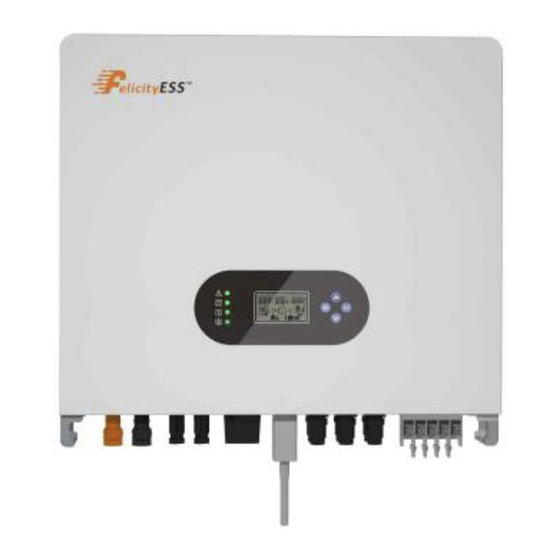
EU WEEE mark 2.Product Introduction FelicityESS T-REX-4K6LP1G01/T-REX-5KLP1G01 is a multifunctional inverter, combining functions of inverter, solar charger and battery charger to offer uninterruptible power support with portable size. Its comprehensive LCD display offers user configurable and easy accessible button operation such as battery charging, AC/solar charging, and acceptable input voltage based on different applications. -
Page 4: Products Overview
Net Weight Gross Weigh Model (mm) (mm) (mm) (KG) (KG) T-REX-4K6LP1G01/T-REX-5KLP1G01 32.4 39.1 8 9 11 3 Installation 3.1 Packing List The inverter 100% strictly inspected before package and delivery. Please check the product package and fittings carefully before installation. -
Page 5: Installation Tools
Hybrid solar inverter Hybrid solar inverter Table 3.1-1 Detailed delivery list ·Inverter cannot be installed near flammable, explosive or strong electro- Name Quantity magnetic equipment. Inverter Battery connector 1 pair Operation manual DC connector 2 pairs WiFi module COM connector Meter+CT(Optional) Expansion Bolts M5 combination screw... -
Page 6: Mounting
Hybrid solar inverter Hybrid solar inverter The installation of inverter should be protected under shelter from direct sunlight or badweather like snow,rain, lightning etc. √ direct sunlight rain exposure no direct sunlight no rain exposure no snow bulid snow bulid Figure 3.3-3 Installation position 3.4 Mounting Screw locking torque 2N. -
Page 7: Battery Connection
Hybrid solar inverter Hybrid solar inverter Hybrid solar inverter Step 2. Connect PV cables to PV connectors.See Figure 4.1-2. Step 1. Prepare battery cables and accessories, and route the battery power cable through the battery cover. Use accessory box accessories, according to the terminal size of the accessory box, choose 50mm²... - Page 8 Table 4.3-1 : Recommended table of AC circuit breakers INVERTER MODEL AC BREAKER SPECIFIFICATION Connection terminal Screw Cap T-REX-4K6LP1G01/T-REX-5KLP1G01 Cable 40A/230V,2P AC Cover · The absence of AC breaker on back-up side will lead to inverter damage if an NOTE electrical short circuit happens on back-up side.
-
Page 9: Smart Meter & Ct Connection
Hybrid solar inverter Hybrid solar inverter 4.4 Smart Meter & CT Connection Table 4.4-3 :Detailed Pin Function Of COM Port On T-REX Position Function Note 485_A2 RS485-2 For Meter 485_B2 — 485_A3 8..1 485_B3 RS485-3 For Remote Monitor 485_B3 Figure 4.4-1 Smart Meter 485_A3 Table 4.4-1 :Smart Meter LED Indications RY_4... -
Page 10: Drms Connection
Hybrid solar inverter Hybrid solar inverter 4.5 DRMS Connection Table 4.5-3 :Port pin allocation table DRMS(Demand response enabling device) is used for Australia and New Zealand installation (also used as remote shutdown function in European countries), in compliance with Australia and New Zealand safety requirements( or European countries). -
Page 11: Lithium Battery Communication
Hybrid solar inverter Hybrid solar inverter 3. Configure battery type to lithium battery on the app 4.6 Lithium Battery Communication Rated Output frequency 50Hz Battery Type Lithium batt... It’s allowed to connect lithium battery and build communication only which it has been configured. -
Page 12: Wiring System
Hybrid solar inverter Hybrid solar inverter 4.8 Wiring System 5.Display and operation This chapter describes the panel displaying and how to operate on the panel, which involves the LCD display, LED indicators and operation panel. 5.1 Operation and Display Panel Hold on the “ESC”... -
Page 13: Lcd Display Icons
Hybrid solar inverter Hybrid solar inverter 5.2 LCD Display Icons Indicates communication is built between inverter and meter 5.3 Base information Page The base information 450V, Indicates Lithium battery type. Indicates communication is built between inverter and battery. 450V, Indicates load level by 1-25%,26-50%,51-75% and 76-100%... -
Page 14: Work Mode
Hybrid solar inverter Hybrid solar inverter 6. Work Mode In this mode, the priority order of load supply source is Solar>Battery>Grid. The priority order of solar power usage is Load>Battery>Grid.And only solar can charge the battery. Example1:PV<Load, PV and Bat will load at the same time. If PV+Bat cannot provide sufficient power to the load, the remaining energy will be provided from the Grid. -
Page 15: Eco Mode
Hybrid solar inverter Hybrid solar inverter Example2:BAT<PV<Load+BAT, PV charges BAT first, and the remaining energy required for Load will be provided by Grid. GRID:1.97KW PV1:3.2KW PV2:3.27KW BAT:2.74KW Backup Load:1.65KW GRID:2.91KW PV1:3.28KW PV2:3.31KW In discharging mode, BAT:4.93KW Backup Load:4.79KW Example1:PV<Load, PV+BAT provide power to Load, BAT provides power to the Grid. Example3:PV>Load+BAT, PV provides power to BAT first, and then to Load, and the remaining energy will be feed to the Grid. -
Page 16: Parallel Installation
Hybrid solar inverter Hybrid solar inverter 7. Parallel installation 7.3.1 Parallel connection of two inverters 7.1 Introduction to Parallel Machines The inverter can be used in parallel in two different operating modes: (1) Single-phase parallel connection for use, supports up to 12 units in parallel, minimum 2 units in parallel, 12 units in parallel to support the maximum output power of 60KW/60KVA. - Page 17 Hybrid solar inverter Hybrid solar inverter 7.3.2 Parallel connection of three inverters 7.3.3 Parallel connection of multiple inverters...
-
Page 18: Three-Phase Parallel Connection
Hybrid solar inverter Hybrid solar inverter 7.4 three-phase parallel connection 7.4.2 Parallel connection of three inverters Note: (1) All input and output power lines of the inverter are connected to the bus through the circuit breaker and are connected in phase sequence. (2) Before the parallel system is powered up and started, please make sure that the battery negative poles of each inverter are connected together, and each inverter make sure that the parallel mode is set. - Page 19 Hybrid solar inverter Hybrid solar inverter 7.4.3 Parallel connection of six inverters 7.4.4 Parallel connection of multiple inverters...
-
Page 20: Lcd Manual Setting Parallel Mode
Hybrid solar inverter Hybrid solar inverter 7.5 LCD Manual Setting Parallel Mode Note: (1) Single-phase systems and three-phase systems manually set parallel mode Sections 7.5.1, 7.5.2, 7.5.3, and 7.5.6 have the same process, Section 7.5.4 is the single-phase parallel setup process, and Section 7.5.5 is the three-phase parallel setup process. -
Page 21: Warning Code Table
Hybrid solar inverter Hybrid solar inverter 8.Warning Code Table Reduce the connected load by switching off some Overload time out equipment. Output short circuited Check if wiring is connected well and remove abnormal load. Input output reverse Confirm that the input and output wiring is correct. Output current sensor failed OP current sensor failed Output voltage is too low... -
Page 22: Appendix
Hybrid solar inverter Hybrid solar inverter Appendix Parallel CAN COMM abnormality Model T-REX-4K6LP1G01 T-REX-5KLP1G01 Test the parallel communication line, restart still have Loss of parallel hosts problems please contact the after-sales service. Battery Input Data Parallel Synchronisation 40V~60V Battery Voltage Range... - Page 23 Hybrid solar inverter Hybrid solar inverter AC Output Data(Back Up) * According to local grid-connected standards Features: Rated output power 4600VA/4600W 5000VA/5000W · Support WiFi for mobile monitoring · 48V low voltage battery, transformer isolation topology Max. Output current · Max. charging/discharging current of 100A Rated AC output voltage 230Vac ·...
Need help?
Do you have a question about the T-REX-5KLP1G01 and is the answer not in the manual?
Questions and answers