Table of Contents
Advertisement
Quick Links
Advertisement
Table of Contents

Related Manuals for Felicitysolar HY-50K-HT


Summary of Contents for Felicitysolar HY-50K-HT
- Page 1 HY-50K-HT 358-010351-00A...
-
Page 2: Table Of Contents
Contents 1.SAFETY & WARNING ..................2 Product Introduction ..................2.1 Products overview ..................3 INSTALLATION ....................3.1 Packing List....................3.2 Installation tools ..................3.3 Installation Environment ................3.4 Mounting ....................4. ELECTRICAL CONNECTION ................4.1 PV Connection ..................4.2 Battery Connection.................. 4.3 Grid, Load and Gen port connection ............ -
Page 3: Safety & Warning
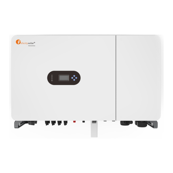
EU WEEE mark 2.Product Introduction Felicity Solar HY-50K-HT is a multifunctional inverter, combining functions of inverter, solar charger and battery charger to offer uninterruptible power support with portable size. Its comprehensive LCD display offers user configurable and easy accessible button operation such as battery charging,... -
Page 4: Products Overview
Product Features - 230V/400V Three phase Pure sine wave inverter. - Self-consumption and feed-in to the grid. - Auto restart while AC is recovering. - Programmable supply priority for battery or grid. - Programmable multiple operation modes: On grid, off grid and UPS. - Configurable battery charging current/voltage based on applications by LCD setting. -
Page 5: Installation
M5 combination screw Model (mm) M10 Allen wrench (mm) (mm) M5 Allen wrench HY-50K-HT 1110 98.4 3 Installation 3.1 Packing List The inverter 100% strictly inspected before package and delivery. Please check the product package and fittings carefully before installation. -
Page 6: Mounting
·Inverter cannot be installed near flammable, explosive or strong electro- ·Do not open the cover of the inverter or replace any part as incomplete inverter magnetic equipment. may cause electric shock and damage the device during operation. The installation of inverter should be protected under shelter from direct sunlight or badweather like snow,rain, lightning etc. -
Page 7: Electrical Connection
Wire Size Cable(mm) 12AWG Step 1. Prepare PV positive and negative power cables Figure 4.1-1 pv cables and pv plugs Step 2. Connect PV cables to PV connectors.See Figure 4.1-2. Figure 4.1-2 PV cables to PV connectors Screw locking torque 2N. m ·... -
Page 8: Battery Connection
Step 3. Connect the battery terminal to the inverter. Ensure that the battery polarity is connected ·The polarity of PV strings cannot be connected reversely, otherwise the correctly. inverter could be damaged. 4.2 Battery Connection Please be careful about any electric shock or chemical hazard.Make sure there is an external DC breaker (25A) connected to the battery without build-in DC breaker. - Page 9 1.On the AC side, the individual breaker should be connected between inverter and Grid but before loads.See Figure 4.3-2. Figure 4.3-2 Ac breaker connection Thread the AC cable through the Screw Cap and connect to the inside of the inverter. Then tighten the Screw Cap.
- Page 10 87654321 Figure 4.4-2 RS485 interface Table:4.4-1:RS485 interface Meter/485B Meter/485A Grid AC Breaker Grid Red line Red line Red line Black line Black line Black line...
- Page 11 DRM1/5 DRM2/6 DRM3/7 DRM4/8...
-
Page 12: Lithium Battery Communication
4.9 Wiring System Table 4.7-1 :Detailed Pin Function Of BMS Port On IVGM L wire N wire PE wire Power Supply 8..1 Ground Lithium Battery Communication AC Breaker DC Breaker AC Breaker PE N L1 L2 L3 AC Breaker AC Breaker GRID... -
Page 13: Typical Application Diagram Of Diesel Generatol
4.10 Typical application diagram of diesel generatol L wire N wire PE wire 5.1 Operation ang Display Panel Once the unit has been properly installed and the batteries are connected well, simply press ON/OFF button (located on the down side of the case) to turn on the unit. When system without battery AC Breaker connected, but connect with either PV or grid, and ON/OFF button is switched off, LCD will still light up (Display will show OFF), In this condition, when switch on ON/OFF button and select NO battery,... -
Page 14: Solar Power Curve
1.The icon in the center of the home screen indicates that the system is Normal operation. This is Grid detail page. If it turns into "comm./F01~F64", it means the inverter has communication errors or other Press the “Energy “ button will enter into errors, the error message will display under this icon (F01-F64 errors, detail error info can the power curve page. -
Page 15: System Work Mode
5.5 System Work Mode Auto Start Charge: Percent SOC below Auto Start Charge, system will AutoStart to charge the battery bank from the generator(or the power grid). Exit Charge: Percent SOC reach Exit Charge, system will stop charging the battery bank from the System Work Mode: generator(or the power grid). -
Page 16: Grid Setting
Grid Peak-shaving: when it is active, grid output power will be limited within the set value. If the load power exceeds the allowed value, it will take PV energy and battery as supplement. If still can’t meet the load requirement, grid power will increase to meet the load needs. It allows users to choose which day to execute the setting of “Time Of Use”. - Page 17 Turn On Ramp Rate: It is the startup and reconnection power ramp, for example, Turn On Ramp Hf1: Level 1 over frequency protection point and protection time; Rate =100%/s, means the output power will increase from 0kw to 100% rated power in 1s. HF2: Level 2 over frequency protection point and protection time;...
- Page 18 U(P): Active power response to Voltage deviation For example: V1=108%, V2=110%, P1=100%,P2=80%. When the grid voltage reaches the 110% times of rated grid voltage, the inverter will limited its output active power to 80% rated power. U(Q): controls the reactive power output as a function of the voltage For example: V1=90%, Q1=50%, V2=95%, Q2=0%, V3=105%, Q3=0%, V4=110%, Q4=-50%.
-
Page 19: Generator Setting
LVRT3: Level 3 undervoltage protection point and protection time; Advanced Function LVRT4: Level 4 undervoltage protection point and protection time; LVRT5: Level 5 undervoltage protection point and protection time. 5.7 Generator Setting DRM: For AS4777 standard. CT Ratio: the CT ratio of the zero-export to CT mode. GFCI: the ground-fault circuit interrupter function. -
Page 20: Work Mode
6. Work Mode Example2:Load<PV<Load+BAT, PV charges BAT first, and the remaining energy required for Load will be provided by Grid. General mode In this mode, the priority order of load supply source is Solar>Battery>Grid. The priority order of solar power usage is Load>Battery>Grid.And only solar can charge the battery. -
Page 21: App Download The App
7. APP Download the app Method 1: Access https://download.felicitysolar.com using the mobile phone browser and download the latest installation package. Method 2: Scan the following QR code and download the latest installation package. In discharging mode: Example1:PV<Load, PV+BAT provide power to Load, BAT provides power to the Grid. -
Page 22: Fault Code
9. Fault Code Battery 2 reverse connection Battery 2 is reversed, check the battery wiring fault Battery 1 SOC Low fault Battery 1 SOC is too low, the battery should be charged Warning Warning Warning Battery 2 SOC Low fault Battery 2 SOC is too low, the battery should be charged Code Information... - Page 23 PV Input Lightning Protection, PV String Input Reverse Polarity Protection,Battery Input Lightning Protection, Battery Input Reverse Polarity Protection,Insulation Resistor Detection, Model HY-50K-HT Residual Current Monitoring Unit, Output Over Integrated Current Protection, Battery Input Data Output Shorted Protection, Output Over Voltage...
Need help?
Do you have a question about the HY-50K-HT and is the answer not in the manual?
Questions and answers
What is this number means on 3.5kva Felicity inverter 15, 16, 17, 18