Table of Contents
Advertisement
Quick Links
Advertisement
Table of Contents

Related Manuals for Dyna-Glo KFA650DGD-1


Summary of Contents for Dyna-Glo KFA650DGD-1
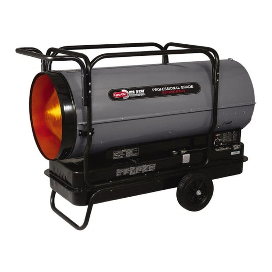
- Page 1 This Owner's Manual is provided and hosted by Appliance Factory Parts. DYNA-GLO KFA650DGD-1 Owner's Manual Shop genuine replacement parts for DYNA-GLO KFA650DGD-1 Find Your DYNA-GLO HVAC Parts - Select From 146 Models -------- Manual continues below --------...
- Page 2 INDOOR/OUTDOOR PRODUCTS KEROSENE PORTABLE FORCED AIR HEATERS “USER’S MANUAL AND OPERATING INSTRUCTIONS” COMPLIES WITH ANSI A10.10-1998 CAN/CSA/B140.0-03 AND CSA B140.8-1967 MODEL : KFA650DGD Before the first use of this heater, please read this USER’S MANUAL very carefully. This USER’S MANUAL has been designed to instruct you as to the proper manner in which to assemble, maintain, store, and most importantly, how to operate the heater in a safe and efficient manner.
-
Page 3: Risk Of Electric Shock
NEVER LEAVE THE HEATER UNATTENDED WHILE BURNING! DANGER: IMPROPER USE OF THIS HEATER CAN RESULT IN SERIOUS INJURY OR DEATH FROM BURNS, FIRE, EXPLOSION, ELECTRICAL SHOCK AND/OR CARBON MONOXIDE POISONING. WARNINGS: 1. RISK OF INDOOR AIR POLLUTION! Use this heater only in well ventilated areas. Provide at least a three-square foot (2,800 sq. cm.) opening of fresh outside air for each 100,000 BTU/hr. -
Page 4: Table Of Contents
NEVER LEAVE THE HEATER UNATTENDED WHILE BURNING! CONTENTS OF USER’S MANUAL ITEM PAGE # REPLACING FUSE 1. INTRODUCTION Please read this USER’S MANUAL carefully. It will show you how to assemble, maintain, and operate the heater safely and efficiently to obtain full benefits from its many built-in features. 2. -
Page 5: Unpacking And Assembly
NEVER LEAVE THE HEATER UNATTENDED WHILE BURNING! 3. UNPACKING AND ASSEMBLY 1. REMOVE THE HEATER AND ALL PACKING MATERIALS FROM THE BOX. (See Fig.2) NOTE: Save the shipping carton and packing materials for future storage. Wheels Cap Nuts Bushings Threaded Axle Harware Kit HW-KFA1020 Figure 2. -
Page 6: K E R O S E N E
NEVER LEAVE THE HEATER UNATTENDED WHILE BURNING! Front Handle Screw Wheel Cap Nut Axle Bushing Figure 3. Assembling Handle & Wheel and Cord wrap 4. KEROSENE (1-K) For optimal performance of this heater, it is strongly suggested that 1-K kerosene be used. 1-K kerosene has been refined to virtually eliminate contaminants, such as sulpher. -
Page 7: Fueling Your Heater
NEVER LEAVE THE HEATER UNATTENDED WHILE BURNING! 5. OVERVIEW OF HEATERS DESIGN Fuel System: This heater is equipped with a Fuel pump(Gear)that pulls fuel through the fuel line connected to the fuel tank and then pushes fuel through a filter and a solenoid valve and out the burner head nozzle. -
Page 8: Operation
NEVER LEAVE THE HEATER UNATTENDED WHILE BURNING! 7. OPERATION A.) VENTILATION RISK OF INDOOR AIR POLLUTION/USE HEATER ONLY IN WELL VENTILATED AREAS. Provide at least a three-square foot(2,800 sq. cm.) opening of fresh outside air for each 100,000 BTU/Hr. of heater rating. B.) OPERATION TO START HEATER 1. -
Page 9: To Restart Heater
NEVER LEAVE THE HEATER UNATTENDED WHILE BURNING! TO STOP HEATER CAUTION ; Never unplug heater while heater is running Heater must go through cooling cycle. The cooling cycle cools the combustion chamber. Damage to heater can occur if combustion chamber is not cooled. -
Page 10: Long Term Storage Of Your Heater
NEVER LEAVE THE HEATER UNATTENDED WHILE BURNING! 8. LONG TERM STORAGE OF YOUR HEATER 1. Remove fuel drain bolt from rear bottom side of fuel tank using 3/4” socket or adjustable wrench and drain. 2. Using a small amount of kerosene, swirl and rinse the inside of the tank. NEVER mix water with the kerosene as it will cause rust inside the tank. -
Page 11: Maintenance
NEVER LEAVE THE HEATER UNATTENDED WHILE BURNING! 9. MAINTENANCE WARNING!! NEVER SERVICE HEATER WHILE IT IS PLUGGED IN OR WHILE HOT! USE ORIGINAL EQUIPMENT REPLACEMENT PARTS. Use of third party or other alternate components will void warranty and may cause unsafe operating conditions. - Page 12 NEVER LEAVE THE HEATER UNATTENDED WHILE BURNING! C.) SPARK PLUG SPARK PLUG CLEAN AND REGAP EVERY 600 HOURS BURNER HEAD OPERATION OR REPLACE AS NEEDED. - Remove upper shell (See page 9). SPARK PLUG WIRE - Remove spark plug wire from spark plug (See Figure 8) - Remove spark plug from burner head using medium phillips screw driver.
- Page 13 NEVER LEAVE THE HEATER UNATTENDED WHILE BURNING! E.) PHOTOCELL CLEAN PHOTO CELL ANNUALLY OR AS NEEDED. - Remove upper shell(See Page 9) - Remove photocell from photocell Bracket and disconnect photocell from connector. - Clean photocell lens with cotton swab. - Inspect photcell lens for damage.
- Page 14 NEVER LEAVE THE HEATER UNATTENDED WHILE BURNING! G.) FUEL FILTER CLEAN TWICE PER HEATING SEASON OR AS NEEDED. Tank Fuel Filter - Remove fan guard.(See page 11). PUMP - Disconnect fuel line (B) from pump and pump SCREW fuel filter assembly with 3/8” wrench (See Figure 13) - Remove two screws that fix bracket-filter to shell lower and remove bracket-filter.
- Page 15 NEVER LEAVE THE HEATER UNATTENDED WHILE BURNING! H.) PUMP PRESSURE ADJUSTIMENT - Remove pressure gauge plug from pump with 1/8” allen wrench. - Install accessory pressure gauge to pressure gauge port. (See Figure 15) - Start heater (See operation, page 6) Allow motor to reach full speed.
-
Page 16: Replacing Fuse
NEVER LEAVE THE HEATER NEVER LEAVE THE HEATER UNATTENDED WHILE BURNING! UNATTENDED WHILE BURNING! 10. REPLACING FUSE 10. REPLACING FUSE NOTICE : This heater is fuse protected. NOTICE : This heater is fuse protected. If your heater fails to ignite, DO NOT RETURN YOUR HEATER TO THE If your heater fails to ignite, DO NOT RETURN YOUR HEATER TO THE STORE. -
Page 17: Troubleshooting Guide
NEVER LEAVE THE HEATER UNATTENDED WHILE BURNING! . TROUBLE SHOOTING GUIDE TROUBLE POSSIBLE CAUSE CORRECTIVE ACTION 1. Wrong pump pressure 1. See Pump Pressure Adjustment, Heater ignites but MAIN PCB page 13. assembly shuts heater off after 2. Dirty Fuel Filter a short period of time. -
Page 18: Wiring Diagram
NEVER LEAVE THE HEATER UNATTENDED WHILE BURNING! . WIRING DIAGRAM CONTROL PCB LIMIT CONTROL BLACK SOL. BLACK BLACK VALVE POWER LAMP SPARK PLUG BLACK (LED) BROWN WHITE IGNITOR BROWN BLACK ROOM ORANGE THERMOSTAT BLACK SENSOR PUMP (TEMP. CONTROL) MOTOR WHITE CAPACITOR CN2(AC2)/ 50uF/400Vac... -
Page 19: Specifications
NEVER LEAVE THE HEATER UNATTENDED WHILE BURNING! . SPECIFICATIONS ( " " 8 . KFA650DGD KFA650DGD Fuel Consumption-Gal./ ( ./Hr) 4.9(18.55) Fuel Tank Capacity-Gal ( ) 29.0(110.0) (kgf/ ) Pump Pressure PSI 110(7.73) s t l Size(W D H), Inch( ) 32.8”... - Page 20 NEVER LEAVE THE HEATER UNATTENDED WHILE BURNING! . EXPLODED PARTS DRAWING (KFA650DGD MODEL) NOTE: SPECIFY MODEL NUMBER AND PART NUMBER WHEN ORDERING PARTS.
-
Page 21: Parts List
NEVER LEAVE THE HEATER UNATTENDED WHILE BURNING! . PARTS LIST PART No. KEY No. DESCRIPTION Quantity KFA650DGD Fuel Tank Assembly 2151-0021-01 Fuel Drain Bolt 4329-0072-00 Bracket-Cord 3131-0357-01 Flange Screw 4319-0015-00 Fuel Gauge 2156-0054-00 Fuel Filter 3221-0009-00 Fuel Cap 2151-0041-00 Filler Neck Assembly 2155-0011-00 Space Support 3713-0004-00... - Page 22 NEVER LEAVE THE HEATER UNATTENDED WHILE BURNING! . PARTS LIST (BURNER HEAD ASSEMBLY & MOTOR AND PUMP ASSEMBLY) NOTE: SPECIFY MODEL NUMBER AND PART NUMBER WHEN DRDERING PARTS. KEY NO. DESCRIPTION PART NO. QTY. Burner Head 3531-0012-00 Plug 3541-0060-00 Nozzle SP-KFA1028 Spark Plug SP-KFA1009...
- Page 23 NEVER LEAVE THE HEATER UNATTENDED WHILE BURNING! . PARTS LIST (Wheel and Handle) NOTE: SPECIFY MODEL NUMBER AND PART NUMBER WHEN ORDERING PARTS. KEY No. DESCRIPTION Quantity PART No. Wheel Support Frame 3551-0041-00 Handle Frame 3551-0043-00 Frame Supportor 3551-0044-00 Front Handle 3551-0042-00 Wheel 3720-0004-00...
- Page 25 GHP Group, Inc. 6440 W Howard St Niles, IL 60714-3302 Tel: (877) 447-4768 www.ghpgroupinc.com GHP Group, Inc. 6440 W Howard St Niles, IL 60714-3302...
Need help?
Do you have a question about the KFA650DGD-1 and is the answer not in the manual?
Questions and answers