
Related Manuals for Larzep WI100


Summary of Contents for Larzep WI100
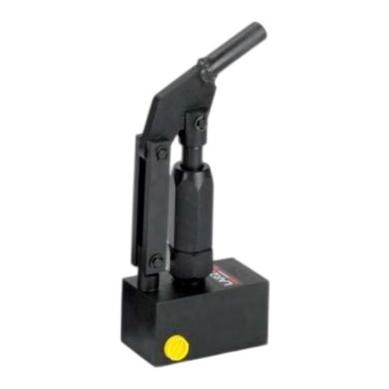
- Page 1 MODULAR HAND PUMP WI100 LARZEP, S.A. Avenida Urtiaga, 6 48269 Mallabia, Spain Tel. +34 943 171200 Fax. +34 943 174166 e‐mail: info@larzep.com www.larzep.com ...
-
Page 2: Table Of Contents
Do not modify the device (welded parts, lengthening drive levers, etc.) without consulting the manufacturer. Do not use the hoses for transporting the device. Use the handles on the cylinders (when appropriate) and set the pump lever to the transportation position. When filling the pump with oil, always use LARZEP hydraulic oil or another oil of similar characteristics. Fill only to the indicated level and remember that the cylinder piston should be back. Before initiating operation, check that the installation is correct, the operator position is safe and the working zone is out of bounds to all personnel. In all cases, the operator should have received adequate training regarding the handling of the device and logical safety criteria associated with the ... -
Page 3: Start Up
If the cylinder has a return spring (SM, SMP, SMX, SH, TE, T, SAM, SAH, CY, KC) the piston will move back automatically. The return speed may be slow in some applications. In this case, we recommend the use of double effect cylinders. In the case of load return cylinders (SP,SX,SL,SSR,STR,STX), you will need to push the piston back using more or less force, depending on the size and position of the cylinder. In cylinders without a mechanical limit switch (SSR, STR, STX) this type of test cannot be carried out. If you do not have a test bench, you will have to test the installation using the actual load in the application. This operation should be carried out with extreme care by experienced personnel and maximum safety measures should be applied. Repeat the process as many times as necessary until you are comfortable handling the device. If using close or check valves, or working with various cylinders via flow distributors, remember to take into consideration the effect these accessories may have on the functioning of the device, and establish an operating procedure in order to avoid unwanted effects. DOUBLE ACTING INSTALLATION The connection of the quick plugs is, if possible, even more important here, since a bad connection will not only prevent the device from functioning, it may also generate excessive pressure build‐up that may cause the cylinder to break. Take note of which hose connects to the thrust chamber and which to the return chamber. All double action LARZEP cylinders are equipped with a mechanical limit switch capable of withstanding the nominal pressure. You can therefore carry out the test described in the previous section. If you are working with another type of cylinder and are not 100% sure, do not carry out this test. Release the pump drive lever by removing the hook from the lever‐holder housing. Turn the control of the distributing valve to the central position and pump and few times to fill the internal channels with oil. Turn the lever to one side and pump. Oil will flow through the hose connected to the side to which the valve lever is rotated. If this hose is connected to the cylinder’s thrust chamber, the piston will move forward. The oil in the return chamber will flow freely through the other hose to the pump tank. Until the moment the cylinder connects with the load, flow is supplied by both the large and small pistons. Continue pumping until you reach the limit switch. At this moment an internal large piston relief value will be triggered, and only the oil supplied by the small piston will be available. Subject the installation to pressure to check for leaks. Stop pumping and check (preferably using a pressure gauge) that the installation maintains the pressure level. Turn the valve lever to the other side and pump. Oil will flow to the return chamber and the piston will move back. The oil in the thrust chamber will flow freely back to the tank. Repeat the process as many times as necessary until you are comfortable handling the device. ... -
Page 4: Declaration Of Conformity
Instruction Manual Modular Hand Pump “WI 100” 6. DECLARATION OF CONFORMITY 4 ... - Page 5 Instruction Manual Modular Hand Pump “WI 100” 5 ...
Need help?
Do you have a question about the WI100 and is the answer not in the manual?
Questions and answers