
Subscribe to Our Youtube Channel
Related Manuals for Larzep HBM Series


Summary of Contents for Larzep HBM Series
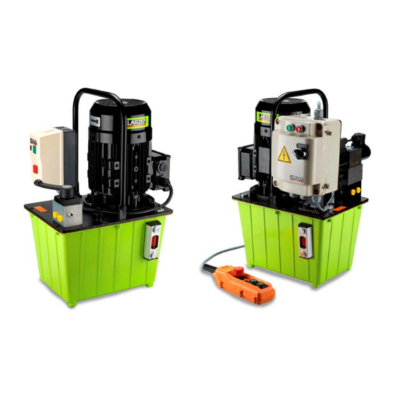
- Page 1 OPERATING AND MAINTENANCE INSTRUCTIONS HYDRAULIC ELECTRICAL PUMPS HBM (Manual control) HBE (Electrical control) LARZEP, S.A. Avenida Urtiaga, 6 48269 Mallabia, Spain Tel. +34 943 171200 Fax. +34 943 174166 e‐mail: info@larzep.com www.larzep.com V02/20 ...
-
Page 2: Table Of Contents
7. DECLARATION OF CONFORMITY .............. 8 ANNEX APPENDIX 1 – General diagram APPENDIX 2 – Hydraulic diagram APPENDIX 3 – Electric diagram 1. SAFETY ESSENTIAL REQUIREMENTS GENERAL CONSIDERATIONS The LARZEP hydraulic electric pumps have been designed in accordance with our Quality Standards and under the control described by the ISO 9001 rules. Nevertheless, improper use may result in the death or serious injury of the user and third parties, as well as causing grave damage to the machine and related materials. Bearing the above in mind, obviously the use of the pump must be done as per the relevant instructions described in the manual. The operator must be aware of the inherent risks when handling high pressure hydraulic devices, command properly the working operation and instruct accordingly the staff staying nearby to the working area. -
Page 3: Technical Features
Instruction Manual Hydraulic Electrical Pumps “HBE” “HBM” All commands should be operated by hand. Do not use any tools or levers for that purpose. When using tools (to regulate the external limiting valve, for example), make sure you select the correct one and do not use excessive force. Make sure about the perfect cleaning of coupling and accessories. Dirty couplings are difficult to connect and might cause dust and other dirty materials entering into the hydraulic circuit. When using electric pump, make sure that the distributor valve is in neutral position when plugging the pump. Ensure that heavy or sharp objects do not fall or are placed on the hose. Do not pressurize the hose by pumping against the coupling, ... - Page 4 Instruction Manual Hydraulic Electrical Pumps “HBE” “HBM” HBE: HYDRAULIC ELECTRIC PUMP WITH SOLENOID VALVE 50‐60 Hz 3 Phase Tank Flow at 700 bar Flow at low P. 230 V 400V Power Weight l l/min l/min S/A D/A S/A D/A kW kg 5 0,36 4,0 HBE7262 HBE7272 HBE7264 HBE7274 0,75 27 8,5 0,54 5,9 HBE3362 HBE3372 HBE3364 HBE3374 1,1 35 12,5 0,54 ...
-
Page 5: Installation And Start-Up
Instruction Manual Hydraulic Electrical Pumps “HBE” “HBM” 3. INSTALLATION AND START UP 3.1 INSTALLATION Read the instructions manual thoroughly and apply the contents. Make sure that the machine has not been damaged during transportation and is clean and complete. Place the machine in a stable and well‐protected area. Use hoses that are long enough to make sure the operator is away from the danger zone. Assemble the complete installation making sure that all accessories (hoses, quick‐couplers, valves, joints, pressure gauges, distributors, cylinders, etc.) are properly connected. Check without a load as indicated in the next point. A good installation is essential to the proper, risk‐free functioning of the machine, and should therefore be carried out by qualified personnel only. Connecting the hoses. Operation of the distributing valve: Two‐position manual control. Single effect cylinder. Type: HBM _ _ 1 _. The distributing valve has a single outlet for connection to the hose. When the lever is set to position ‘P’ (towards the hose outlet), the cylinder moves out. Turning the lever to position ‘T’ (opposite direction), causes the cylinder to return, because of the action of the spring or the weight of the load itself. ... - Page 6 Instruction Manual Hydraulic Electrical Pumps “HBE” “HBM” Use a pressure gauge at this point to check that the internal safety valve is set correctly to 700 bar. If you wish to check the pressure of an installation without pressing the remote pendant (open centre, ‘P’ connected to ‘T’ and forward and back movements blocked) or with the manual control set to ‘C’, you should place the pressure gauge and its corresponding gauge adaptor in the output of the distributing valve. If you do not press the remote pendant or the manual valve control is set to ‘C’, the distributing valve’s check valves will maintain the pressure in the circuit. If the proposed operating pressure is less than 700 bar, use the external pressure relief valve. Use a spanner to loosen the lock nut and a screwdriver to loosen (counter‐clockwise – reduces pressure) or tighten (clockwise – increases pressure) the adjustment screw. Use a pressure gauge to check that the desired operating pressure has been reached, and then block the ...
-
Page 7: Maintenance
Please note that if the equipment is disassembled or serviced by anyone other than an authorized service dealer or by LARZEP, S.A., this guarantee is rendered null and void. In the event of a warranty claim, return the equipment, to LARZEP, S.A. or the authorized dealer which sold you the hydraulic equipment, ... -
Page 8: Declaration Of Conformity
Instruction Manual Hydraulic Electrical Pumps “HBE” “HBM” 7. DECLARATION OF CONFORMITY 8 ... - Page 9 Instruction Manual Hydraulic Electrical Pumps “HBE” “HBM” # DESCRIPTION 1 External Pressure Relief Valve 2 Plug 3 Valve 4 Pump 5 Lid 6 Distributor 7 Motor 8 Handle 9 Level 10 Tank 9 ...
- Page 10 Instruction Manual Hydraulic Electrical Pumps “HBE” “HBM” # DESCRIPTION 1 External Pressure Relief Valve 2 Plug 3 Valve 4 Pump 5 Lid 6 Distributor 7 Motor 8 Handle 9 Level 10 Tank ...
- Page 11 Instruction Manual Hydraulic Electrical Pumps “HBE” “HBM” COMPONENTS ...
- Page 12 Instruction Manual Hydraulic Electrical Pumps “HBE” “HBM” HYDRAULIC SCHEME VALVE ...
- Page 13 Instruction Manual Hydraulic Electrical Pumps “HBE” “HBM” ...
- Page 14 Instruction Manual Hydraulic Electrical Pumps “HBE” “HBM” ...
Need help?
Do you have a question about the HBM Series and is the answer not in the manual?
Questions and answers