Table of Contents
Advertisement
Quick Links
Advertisement
Table of Contents

Related Manuals for uAvionix ping200XR TSO


Summary of Contents for uAvionix ping200XR TSO
- Page 1 ping200XR User and Installation Guide UAV-1007121-001 Rev B...
- Page 2 retained.
-
Page 3: Revision History
1 Revision History Revision Date Comments 2/26/2024 Initial release 7/31/2024 GPS antenna port current specification UAV-1007121-001 Rev B... -
Page 4: Warnings / Disclaimers
2 Warnings / Disclaimers All device operational procedures must be learned on the ground. uAvionix is not liable for damages arising from the use or misuse of this product. This equipment is classified by the United States Department of Commerce's Bureau of Industry and Security (BIS) as Export Control Classification Number (ECCN) 7A994. -
Page 5: Limited Warranty
For the duration of the warranty period, uAvionix, at its sole discretion, will repair or replace any product which fails in normal use. Such... -
Page 6: Table Of Contents
5.8 Continued Airworthiness ............... 15 5.9 System Limitations ................ 16 5.10 Regulatory Compliance ............. 16 System Specifications ................ 18 6.1 System Functionality ..............18 6.2 ping200XR TSO Specifications ............. 18 6.2.1 General Specifications............18 6.2.2 Mode S Transponder Specifications ........19 6.2.3 Altitude Encoder Specifications .......... - Page 7 Installation ..................22 7.1 Unpacking and Inspecting ............. 22 7.2 Authorized Part Numbers.............. 22 7.3 Installation Materials and Tools ............ 22 7.4 Additional Required Equipment ............ 23 7.5 Mounting ..................23 7.6 Wiring ................... 24 7.7 Transponder Antenna ..............25 7.8 GPS Antenna ................
- Page 8 9.2 Control ..................34 9.3 Post-Installation Checks ............... 34 9.4 Software Part Number ..............37 9.5 Altitude Encoder Calibration ............38 10 Normal Operation ................39 11 Maintenance ..................39 12 Support ....................39 Appendix A Control Interface ..............40 Appendix B Equipment Compatibility and Interconnect Drawings ...
-
Page 9: System Information
5 System Information 5.1 Certification This installation manual provides mechanical and electrical information necessary to install ping200XR. It is not equivalent to an approved airframe-specific maintenance manual, installation design drawing, or installation data package. The content of this manual assumes use by competent and qualified personnel using standard maintenance procedures in accordance with Title 14 of the Code of Federal Regulation and other related accepted procedures. -
Page 10: Tso Authorization
5.2 TSO Authorization ping200XR complies with the following TSOs when properly installed and interfaced with equipment as detailed in this guide. Function TSO / MPS Class / Type Air Traffic Control Radar Beacon Level 2els, TSO-C112e System/Mode Select (ATCRBS / Class 1 RTCA/DO-181E Mode S) Airborne Equipment... -
Page 11: Tso Deviations And Incomplete
Paragraphs 3.e and 6.f to use RTCA/DO-178C in place of RTCA/DO-178B. C112e uAvionix was granted a deviation to not implement Utility Message (UM Field) support, consistent with RTCA/DO-181F and FAA/TSO-C112f Level 2 transponder requirements. This impacts the Mode S Level 2 transponder SARPs requirements as contained in ICAO Annex 10 Volume IV §§3.1.2.6.5.3.1, 3.1.2.6.11.3.2.1.3, 3.1.2.6.11.3.4.2.2, and... -
Page 12: Fcc Id
C112e uAvionix was granted a deviation to not implement Air-Initiated Comm-B support, consistent with RTCA/DO-181F Level 2 and FAA/TSO-C112f transponder requirements. Air-initiated Comm-B messages are neither processed nor transmitted. This impacts the Mode S Level 2 transponder SARPs requirements as contained in ICAO Annex 10 Volume IV §§2.1.5.1.2 and 3.1.2.6.11.3. -
Page 13: Device Marking
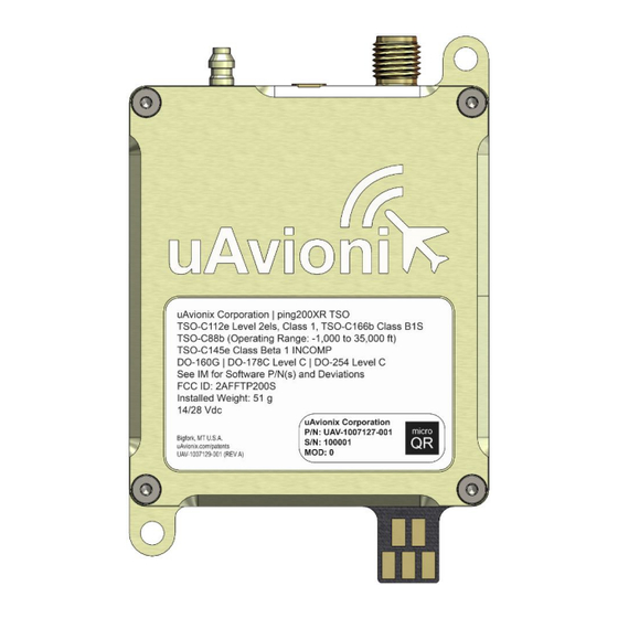
5.6 Device Marking 5.6.1 ping200XR Hardware 5.6.2 ping200XR Software The software contained in ping200XR is identified by electronic marking. Reference Section 9.4 for information on determining the software part number. UAV-1007121-001 Rev B... -
Page 14: Environmental Qualification Form
5.7 Environmental Qualification Form DO-160G Conditions Description of Conducted Tests Section Temperature and Altitude Equipment tested to Categories B2,C4 Low temperature ground survival 4.5.1 -55°C Low Temperature Short-Time 4.5.1 -35°C Operating Low Temperature Operating 4.5.2 -35°C (see Note 1) High Temperature Operating 4.5.4 +70°C High Temperature Short-Time... -
Page 15: Continued Airworthiness
Annually, confirm the ADS-B software version is current per Service Bulletins available at the uAvionix website. The aircraft must be returned to service in a means acceptable to the appropriate aviation authority. -
Page 16: System Limitations
5.9 System Limitations Installation This article meets the minimum performance and quality control standards required by a technical standard order (TSO). Installation of this article requires a separate approval. GNSS Fault Detection Prediction Cannot be used for navigational guidance where Fault Detection (FD) prediction capability is required, such as during execution of certain approach operations outside of SBAS coverage. - Page 17 For additional guidance on ADS-B OUT installation and approvals, reference AC 20-165B. UAV-1007121-001 Rev B...
-
Page 18: System Specifications
This transponder replies to both legacy Mode A/C interrogations and to Mode S interrogations from both ground radar and airborne collision avoidance systems. In all cases, the interrogations are received by the transponder on 1030MHz and replies are transmitted on 1090MHz. 6.2 ping200XR TSO Specifications 6.2.1 General Specifications Characteristics Specifications Width 47.00 mm... -
Page 19: Mode S Transponder Specifications
6.2.2 Mode S Transponder Specifications Characteristics Specifications Transmit frequency 1090 MHz Transmit power 54 dBm (250 W) Receive frequency 1030 MHz ATCRBS sensitivity -74 dBm Mode S sensitivity -74 dBm 50 Ω RF Impedance RF Connector 6.2.3 Altitude Encoder Specifications Characteristics Specifications TSO-C88b Operating Range... -
Page 20: Control Interface Specifications
Sensitivity Tracking -166 dBm Reacquisition -160 dBm Cold Start -148 dBm Hot Start -160 dBm Horizontal position accuracy 5 m RMS with SBAS Velocity accuracy 3 m/s TTFF (Time to First Fix) 58 seconds typical with current almanac and position Reacquisition 1 second typical Position update interval... - Page 21 UAV-1007121-001 Rev B...
-
Page 22: Installation
Software UAV-1002393-( ) 7.3 Installation Materials and Tools ping200XR requires configuration, either using the available uAvionix Windows-based application, or dynamically using the described configuration protocol. Typical installations will be configured using: • “ping200X Control & Config” Windows application, UAV-1004567- •... -
Page 23: Additional Required Equipment
7.4 Additional Required Equipment ping200XR is a “remote” transponder. To fully function it requires connection to a controlling device, often referred to as a control head. It is possible to statically configure ping200XR, but certain capabilities, such as changing the squawk code and responding to annunciations, will not be available when no controlling device is connected. -
Page 24: Wiring
7.6 Wiring ping200XR requires connections to power, ground and an RS-232 control interface. 4-wire Control Interface Color Type Function Power Aircraft Power Input Power Black Aircraft Ground Input Data Grey Control RS-232 Transmit Output Data Orange Control RS-232 Receive Input If new power wiring is required, refer to AC 43.13-1B Chapter 11 for guidance. -
Page 25: Transponder Antenna
• The antenna should be mounted external to the airframe, and typically on the bottom of the aircraft. • The antenna should be mounted in a vertical orientation when the aircraft is in level flight. For uAvionix UAV-1004675-003, see below for proper orientation. UAV-1007121-001... -
Page 26: Gps Antenna
4 feet from any aircraft transmit antennas and have a clear view of the sky with no obstructions. For applications where a TSO antenna is not required, uAvionix non-TSO GPS antenna (part number UAV-1007165-001) has been shown compatible. -
Page 27: Cooling Requirements
Upon completion of installation, a case leak test should be performed per 14 CFR Part 43 Appendix E. If an external altitude encoding source is configured, the internal altitude encoder is unused, and the static pressure system does not need to be connected to the ping200XR static pressure port. -
Page 28: Control And Configuration Interface
8 Control and Configuration Interface ping200XR has a control and configuration serial interface. It is used to configure the equipment at installation time, and to control the device while operating. Typically, a control head or unmanned aircraft flight control computer is connected to the device during operation. Transponder control provides the ping200XR with data such as operating mode, emergency status, squawk code, IDENT, and optionally external pressure altitude information. -
Page 29: Configuration
Set ‘Conn Type’ to ‘Serial’, ‘Port’ to the USB or serial port connected to the ping200XR, ‘App Baud’ to ‘57600’ and ‘Protocol’ to ‘UCP’. Verify the COM Settings Click ‘Start’. 9.1 Configuration The configuration items list below should be used to document the system installation for future reference. -
Page 30: Icao Address
L ≤ 15 Aircraft Length (m) W ≤ 23 Aircraft Width (m) “ “ Aircraft Registration GPS Antenna Lateral Offset (m) Applied by GPS Antenna Longitudinal Offset (m) sensor No Information Aircraft Emitter Type Available UAT RX ADS-B In Capability 1090ES RX Baro Altitude Source Internal... -
Page 31: Aircraft Stall Speed
9.1.3 Aircraft Stall Speed The default aircraft stall speed is 0. Set as appropriate for your aircraft to allow automatic air/ground state determination. Set to 0 to lock in airborne state, or to allow switching by the control head. See Appendix A for more details. -
Page 32: Aircraft Emitter Type
significant offset in antenna position could mean the aircraft footprint is not in the same place as the ADS-B reported position. Although the GPS Antenna Offset is primarily intended for position correction on large transport aircraft, General Aviation aircraft can also have a significant offset. -
Page 33: Serial Port Baud Rate
9.1.10 Serial Port Baud Rate This setting configures the speed of the control interface serial baud rate in bps. 9.1.11 SIL / SDA Set SIL according to the advertised integrity level of the GPS source. • If the ping200XR is configured to use the internal GPS source, set the SIL to 3 (default). -
Page 34: Baro Altitude Resolution
9.1.14 Baro Altitude Resolution The barometric pressure altitude source resolution default is 25 (ft). 9.1.15 In / Out Protocols The default In / Out protocols are UCP. 9.2 Control The ‘Control’ tab allows the installer to exercise and verify the transponder’s operation. - Page 35 To ensure compliance with regulations in the United States, verify functionality identified in 14 CFR Part 43 Appendix F (ATC Transponder Tests and Inspections) and 14 CFR Part 43 Appendix E (Altimeter System Test and Inspection). Aircraft with ping200XR installed may be subject to requirements in 14 CFR 91.215, 91.225 and 91.227.
- Page 36 STEP CHECK If you are in range of Radar or connected to an interrogating test set, ‘Transponder Status’ will indicate interrogations If not already in airborne state, access the ‘Service’ tab and select ‘Enable Ground Test Mode’ - This will enable airborne state until the ping200XR is power cycled Return to ‘Control’...
-
Page 37: Software Part Number
Launch the ‘ping200X Control & Config’ Windows application. Confirm the displayed ‘P/N’ and ‘Version’ on the ‘Firmware Version’ section of the ‘Service’ tab is current per Service Bulletins listed at: https://uavionix.com/support/ping200XR/ If not current, apply Service Bulletins as appropriate to update the software. UAV-1007121-001... -
Page 38: Altitude Encoder Calibration
9.5 Altitude Encoder Calibration STEP CHECK Launch the ‘ping200X Control & Config’ Windows application Set Port to the USB or serial port connected to the ping200XR Set the ‘App Baud’ to value noted in Section 9.1 Set ‘Protocol’ to value noted in Section 9.1 Apply power from a minimum of a 11V, 1A power source Press ‘Start’... -
Page 39: Normal Operation
Mode S, Extended Squitter), during all phases of flight including surface movement operations. 11 Maintenance The ping200XR is not a user serviceable product. All service must be performed either by uAvionix or an authorized uAvionix repair center. 12 Support For additional questions or support please visit: https://www.uavionix.com/support/... -
Page 40: Appendix A Control Interface
Transponder Configuration message. UCP or UCP-HD input is required to be enabled to allow device configuration. A.1 UCP uAvionix Control Protocol (UCP) is documented in uAvionix UCP Transponder Interface Control Document UAV-1002375-001. This document is made available to authorized parties, and may be obtained by contacting uAvionix. - Page 41 Mode To set the transponder operating mode, appropriate enable bits must be set in the Control message. The mapping of traditional transponder modes to required Control message enablement bits follows. Operating Mode Mode A Mode C Mode S 1090ES STBY ON (suppress altitude) Flight Identification...
- Page 42 Unable to communicate with GNSS subsystem (RTCA/DO- Unavailable 260B §2.2.11.6) A.2 UCP-HD uAvionix Control Protocol – Half Duplex (UCP-HD) is documented in uAvionix UCP Transponder Interface Control Document UAV-1002375- 001. This document is made available to authorized parties, and may be obtained by contacting uAvionix.
- Page 43 A.3 Apollo Apollo can be used to control and monitor status of the ping200X. To use, ensure Apollo is enabled as an input protocol. Once an Apollo message is received, Apollo message output is enabled until device reset. A.3.1 Supported Input Messages The following input messages are supported: Mode (#MD) The Mode message configures the operating mode, Mode A (squawk)
-
Page 44: Appendix B Equipment Compatibility And Interconnect Drawings
Protocol must be enabled on ping200XR and baud rate set to 2400 See below for example interconnect drawings. B.2.1 AV-30-C or AV-30-E Control Head This installation uses the ping200XR’s internal truFYX GPS for position data. The uAvionix AV-30-C or AV-30-E provides control, status, and altitude encoder data. UAV-1007121-001 Rev B... - Page 45 Configure the ping200XR as appropriate, ensuring the following values have been updated from defaults: Parameter Value In Protocols UCP-HD Out Protocols UCP-HD Serial Port Baud Rate 2400 Baro Altitude Source External B.3 Third-party Equipment The following devices are reported to be compatible with supported ping200XR control protocols.
- Page 46 ping200XR Manufacturer Model Configuration Function Provided Protocol MINI-B MINI-AP Serial Output: SL70/STX175 MINI-X Apollo Control Serial Rate: 57600 Sport EX Horizon iEFIS Type: STX165(R) Apollo Control Xtreme Serial Rate: 57600 EFIS Proper operation of the interface and system, with the specific equipment configuration, must be demonstrated at installation time.
- Page 47 Example pinout options for certain compatible EFIS displays are shown below. Please consult the EFIS installation manuals for additional options and information. GRT Mini-X Serial Serial / Mini-AP TXD Pin GRT Mini-B Serial Serial Serial TXD Pin GRT Sport EX Serial Serial Serial...
Need help?
Do you have a question about the ping200XR TSO and is the answer not in the manual?
Questions and answers