Table of Contents
Advertisement
Quick Links
Advertisement
Table of Contents

Related Manuals for uAvionix pingStation 2


Summary of Contents for uAvionix pingStation 2
- Page 1 2 User and Installation Guide REVISION A UAV-1005004-001 Page 1 | 28...
- Page 2 retained.
-
Page 3: Revision History
1 Revision History Revision Date Comments 11/23/2020 Initial release UAV-1005004-001 Page 3 | 28... -
Page 4: Warnings / Disclaimers
2 Warnings / Disclaimers All device operational procedures must be understood prior to operation. uAvionix is not liable for damages arising from the use or misuse of this product. UAV-1005004-001 Page 4 | 28... -
Page 5: Limited Warranty
3 Limited Warranty uAvionix pingStation 2 products are warranted to be free from defects in material and workmanship for one year from purchase. For the duration of the warranty period, uAvionix, at its sole option, will repair or replace any product which fails under normal use. -
Page 6: Table Of Contents
Configuration Items ............... 14 7.3.2 Health Statistics ..............15 Update ....................16 Update the pingStation 2 system software ........16 Update ADS-B receiver software ..........18 Virtual Radar Server Receiver ............20 Configure pingStation 2............... 20 Configure Virtual Radar Server ........... 22 Configure Virtual Radar Moving Map Home Location .... -
Page 7: Introduction
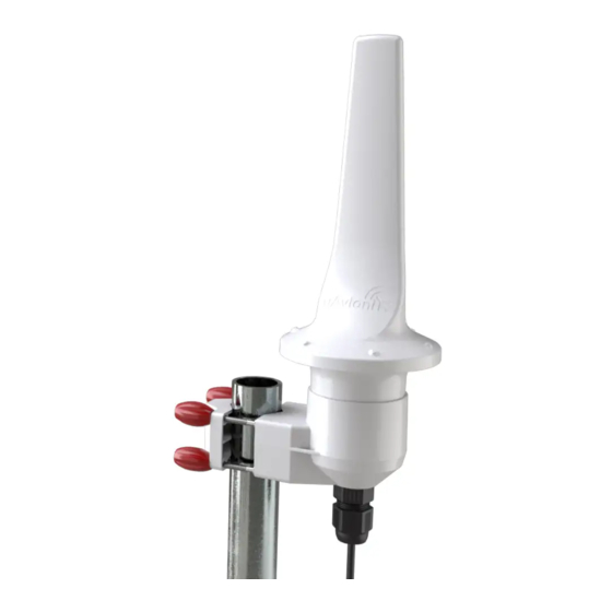
5 Introduction pingStation 2 is a dual band (978MHz and 1090MHz), networkable ADS-B receiver with a Power-Over-Ethernet (POE) interface enclosed in an IP67 rated protective enclosure. pingStation 2 provides ground surface or low-altitude ADS-B surveillance within line of sight of the antenna, with range dependent upon the output power of the transmitting ADS-B transceiver. -
Page 8: Installation
Mount pingStation 2 as high on the pole as possible, preferably at the top with an unobstructed 360° view of the sky. Install the knobs evenly until all four have made light contact with the clamp block. - Page 9 Firmly seat the pingStation 2 unit all the way to the bottom of the clamping bracket cup. Connect the pingStation 2 using Cat5e or better ethernet cable. You may wish to use shielded Cat5e cable to protect against EMI interference depending on your installation location.
-
Page 10: Connection To The Poe Network
6.2 Connection to the POE network pingStation 2 is compatible with existing POE 803.3af standard (Power Class 0) and 802.3af Ethernet cabling. Any POE switch, injector, or cable conforming to these standards should be interoperable with pingStation 2. POE Specifications:... -
Page 11: Configuration
2 install with POE switch pingStation 2 install with POE injector At power-up an IP address will be assigned to the pingStation 2 by the local DHCP server. This IP address is dynamic and assigned by your local network. Determining the assigned IP address is required for configuration. -
Page 12: Configuration Url
Optional: You may wish to configure your DHCP server to reserve an IP address for pingStation 2 in order to ensure its address does not change in the future. Refer to your router or DHCP server instructions for how to reserve IP addresses. -
Page 13: Connect
7.3 Connect The base URL displays configuration items as well as dynamic pingStation 2 statistics. UAV-1005004-001 Page 13 | 28... -
Page 14: Configuration Items
Entering zero results in all aircraft data being returned. Station Info Interval In This is the rate that the pingStation 2 information packet is Seconds returned. Mobile pingStation 2s will want a lower number in this field for more regular GPS updates. The default is once every 30 seconds. -
Page 15: Health Statistics
1 = Not locked 2 = 2D fix 3 = 3D fix 4 = Differential GPS fix GPS Satellites The number of satellites the pingStation 2 can currently see. Latitude The latitude of this pingStation 2. Longitude The longitude of this pingStation 2. -
Page 16: Update
8 Update The pingStation 2 supports software upgrades thru a web-based flashing system. The user will launch the update webpage, select a firmware binary file and press a button to start the update process. There are two separate firmware files which can be updated through this process, the system software, and the ADS-B receiver software. - Page 17 Press to start the upgrade process. There will be an update % status at the bottom of the page. When the upgrade is complete the pingStation 2 will reset. UAV-1005004-001 Page 17 | 28...
-
Page 18: Update Ads-B Receiver Software
8.2 Update ADS-B receiver software The pingStation 2 system software supports in field updating of the ADS-B receiver software. From the pingStation 2 configuration page http://###.###.###.###/ select the “Update” link in line with the ADS-B Version report, or access the updater directly at http://###.###.###.###/pingUpdate... - Page 19 The progress bar will cycle during the update. At completion the updater will report the status of the update. The status will report “Update Complete” if successful. Return to the pingStation 2 configuration page http://###.###.###.###/ and verify the receiver version matches the version uploaded. UAV-1005004-001...
-
Page 20: Virtual Radar Server Receiver
Virtual Radar Server (VRS) software. VRS is not a uAvionix product. This is an example of creating a Virtual Radar Server receiver that will render the Compressed VRS data from the pingStation 2 on a local LAN VRS installation. 9.1 Configure pingStation 2 Open the pingStation 2 setup screen by visiting the pingStation 2 IP address using a web browser. - Page 21 UAV-1005004-001 Page 21 | 28...
-
Page 22: Configure Virtual Radar Server
4. Click the + (plus sign) 5. Enter a name for the receiver 6. Enter the latitude and longitude 7. Click OK Note: Receiver latitude and longitude are available from the pingStation 2 webpage Select Receivers and click the + (plus sign). UAV-1005004-001... - Page 23 Select Enabled Name: Enter a name for the receiver Format: Compressed VRS Location: Choose the receiver location from the dropdown Connection Type: Network Push Receiver: Use to have the pingStation 2 create the TCP connect UAV-1005004-001 Page 23 | 28...
- Page 24 Address: Enter pingStation 2 IP address to TCP connect Port: Enter the same TCP port as pingStation 2 setup Send Keep-alive: Select Enabled Click OK 10. After setup verify that the Virtual Radar Server shows a Connected status and that the message counter is increasing. Note that you may be required to have traffic before the state will change to Connected.
-
Page 25: Configure Virtual Radar Moving Map Home Location
9.3 Configure Virtual Radar Moving Map Home Location 1. To view the aircraft on a moving map open a browser to your Virtual Radar installation. The default address is: http://127.0.0.1/VirtualRadar A clickable hyperlink to the page is located on the Virtual Radar Server window. - Page 26 UAV-1005004-001 Page 26 | 28...
- Page 27 2. From the Virtual Radar webpage click Menu > Options 3. Select the General tab 4. Select Set Current Location 5. Click the X (close) 6. Click and drag the red location icon to your location on the map. UAV-1005004-001 Page 27 | 28...
-
Page 28: Support
For Virtual Radar Server documentation visit: http://www.virtualradarserver.co.uk/ 10 Support For support with pingStation 2 visit http://uavionix.com/support/ UAV-1005004-001 Page 28 | 28...
Need help?
Do you have a question about the pingStation 2 and is the answer not in the manual?
Questions and answers