Table of Contents
Advertisement
Quick Links
Advertisement
Table of Contents

Related Manuals for uAvionix pingStation3


Summary of Contents for uAvionix pingStation3
- Page 1 pingStation 3 User and Installation Guide REVISION A UAV-1005950-001 Page 1 | 31...
- Page 2 retained.
-
Page 3: Revision History
1 Revision History Revision Date Comments 11/1/2021 Initial release UAV-1005950-001 Page 3 | 31... -
Page 4: Warnings / Disclaimers
2 Warnings / Disclaimers All device operational procedures must be understood prior to operation. uAvionix is not liable for damages arising from the use or misuse of this product. UAV-1005950-001 Page 4 | 31... -
Page 5: Limited Warranty
3 products are warranted to be free from defects in material and workmanship for one year from purchase. For the duration of the warranty period, uAvionix, at its sole option, will repair or replace any product which fails under normal use. Such repairs or replacement will be made at no charge to the customer for parts or labor, provided that the customer shall be responsible for any transportation cost. -
Page 6: Table Of Contents
4 Contents Revision History ................... 3 Warnings / Disclaimers ................ 4 Limited Warranty .................. 5 Introduction ..................7 Installation ................... 9 Mechanical Mounting Recommendations ........9 Connection to the POE network ..........11 Configuration ..................12 POE Installation ................12 Configuration URL .............. -
Page 7: Introduction
5 Introduction pingStation 3 is a dual band (978MHz and 1090MHz), networkable ADS-B receiver with a Power-Over-Ethernet (POE) interface enclosed in an IP67 rated protective enclosure. pingStation 3 provides ground surface or low- altitude ADS-B surveillance within line of sight of the antenna, with range dependent upon the output power of the transmitting ADS-B transceiver. - Page 8 Figure 1:pingStation 3-dimensional drawing UAV-1005950-001 Page 8 | 31...
-
Page 9: Installation
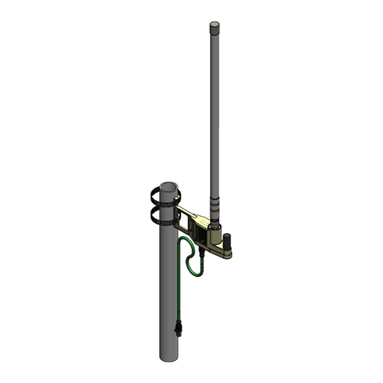
6 Installation 6.1 Mechanical Mounting Recommendations pingStation 3 is supplied with an installation bracket and hose clamps to mount to poles of various sizes. Figure 2: Installation views from below (left) and above (right) UAV-1005950-001 Page 9 | 31... - Page 10 Seat and tighten the hose clamp mount into the pingStation 3 and secure with provided screws using a screwdriver. Select the appropriate hose clamp size based on the diameter of the mounting pole. Tighten hose clamps to secure pingStation 3 to the mounting pole. Connect the pingStation 3 with the M12 connector using Cat5e or better ethernet cable.
-
Page 11: Connection To The Poe Network
6.2 Connection to the POE network The pingStation 3 connects to a network via POE using an M12 X-Coded connector. POE Specifications: Parameter Value Standard 802.3af (802.3at Type1) Maximum power 15.4W 37 – 57V Voltage Range Maximum Current 350mA Maximum Cable Resistance 20Ω... -
Page 12: Configuration
7 Configuration 7.1 POE Installation pingStation 3 must be powered via POE. This can be accomplished with a POE capable switch, or with a standalone POE injector. Connect the shielded POE cable to an active POE switch or a regular switch via a Class 0 POE power injector as shown below. -
Page 13: Configuration Url
At power-up an IP address will be assigned to the pingStation 3 by the local DHCP server. This IP address is dynamic and assigned by your local network. Determining the assigned IP address is required for configuration. The pingStation 3 IP address can be determined by accessing the local DHCP server and reviewing the connected devices or by using industry accepted network scanning tools. -
Page 14: Connect
7.3 Connect Note: Any IP addresses shown in this document are examples only, and are not applicable to your pingStation 3 IP address. The base URL displays configuration items as well as dynamic pingStation 3 statistics. Figure 6: Example configuration screen UAV-1005950-001 Page 14 | 31... -
Page 15: Configuration Items
TCP server will listen for incoming connections on to deliver the compressed VRS tracking data. pingStation3 IP networking options for pingStation3. Default Network is DHCP, static IP optional. Warning: Only use Address static IP if necessary, it is possible to lock access out of pingStation3 if configured incorrectly. - Page 16 Configuration Configuration Description Category Item Static IP Fixed IP address number of the device which Address will not change. The network administrator assigns this number. Set this field to 0.0.0.0 to enable DHCP (Default). Subnet Mask Mask used to the IP address into network and host address.
- Page 17 Note: When modifying any configuration item, press the Update button to store the changes. These fields are non-volatile and persist through power cycles. UAV-1005950-001 Page 17 | 31...
-
Page 18: Health Statistics
7.3.2 Health Statistics Statistic Description UAT Basic The number of UAT basic aircraft messages received. UAT Long The number of UAT long aircraft messages received. 1090 DF17 The number of 1090 ADS-B aircraft messages received. 1090 DF18 The number of 1090 TIS-B messages received. Current Aircraft The number of aircraft currently being tracked. -
Page 19: Update
8 Update The pingStation 3 supports software upgrades thru a web-based flashing system. The user will launch the update webpage, select a firmware binary file and press a button to start the update process. There are two separate firmware files which can be updated through this process, the system software, and the ADS-B receiver software. - Page 20 Figure 8: Example UAV file update selection screen Press to start the upgrade process. There will be an update % status at the bottom of the page. When the upgrade is complete the pingStation 3 will reset. Figure 9: Example restart screen UAV-1005950-001 Page 20 | 31...
-
Page 21: Update Ads-B Receiver Software
8.2 Update ADS-B receiver software The pingStation 3 system software supports in field updating of the ADS-B receiver software. From the pingStation 3 configuration page http://###.###.###.###/ select the “Update” link in line with the ADS-B Version report, or access the updater directly at http://###.###.###.###/pingUpdate Figure 10: ADS-B receiver software version From the pingUpdate page select “Choose File”... - Page 22 Figure 12: Update progress bar Return to the pingStation 3 configuration page http://###.###.###.###/ and verify the receiver version matches the version uploaded. Figure 13:Check updated ADS-B version UAV-1005950-001 Page 22 | 31...
-
Page 23: Virtual Radar Server Receiver
Open the pingStation 3 setup screen by visiting the pingStation 3 IP address using a web browser. Enable the TCP Compressed VR output Enter an IP Address or hostname i.e.192.168.0.200 or vrs.uavionix.com Enter the assigned TCP port i.e. 30003 Note: To display traffic on vrs.uavionix.com, please contact uAvionix support to obtain an assigned TCP port. - Page 24 UAV-1005950-001 Page 24 | 31...
-
Page 25: Configure Virtual Radar Server
9.2 Configure Virtual Radar Server Download and install Virtual Radar Server from: http://www.virtualradarserver.co.uk/ 1. Open Virtual Radar Server 2. Select Tools > Options 3. Select Receiver Locations 4. Click the + (plus sign) 5. Enter a name for the receiver 6. - Page 26 9. Configure a receiver as shown below: Enable: Select Enabled Name: Enter a name for the receiver Format: Compressed VRS Location: Choose the receiver location from the dropdown Connection Type: Network Push Receiver: Use to have the pingStation 3 create the TCP connect UAV-1005950-001 Page...
- Page 27 Address: Enter pingStation 3 IP address to TCP connect Port: Enter the same TCP port as pingStation 3 setup Send Keep-alive: Select Enabled Click OK 10. After setup verify that the Virtual Radar Server shows a Connected status and that the message counter is increasing. Note that you may be required to have traffic before the state will change to Connected.
-
Page 28: Configure Virtual Radar Moving Map Home Location
9.3 Configure Virtual Radar Moving Map Home Location 1. To view the aircraft on a moving map open a browser to your Virtual Radar installation. The default address is: http://127.0.0.1/VirtualRadar A clickable hyperlink to the page is located on the Virtual Radar Server window. - Page 29 UAV-1005950-001 Page 29 | 31...
- Page 30 2. From the Virtual Radar webpage click Menu > Options 3. Select the General tab 4. Select Set Current Location 5. Click the X (close) 6. Click and drag the red location icon to your location on the map. UAV-1005950-001 Page 30 | 31...
-
Page 31: Support
For Virtual Radar Server documentation visit: http://www.virtualradarserver.co.uk/ 10 Support For support with pingStation 3 visit http://uavionix.com/support/ UAV-1005950-001 Page 31 | 31...
Need help?
Do you have a question about the pingStation3 and is the answer not in the manual?
Questions and answers