
Subscribe to Our Youtube Channel
Related Manuals for Symphony SYK-1031


Summary of Contents for Symphony SYK-1031
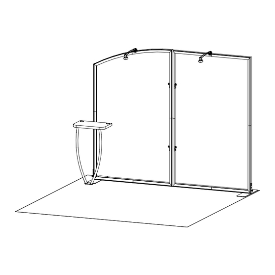
- Page 1 © 2024 Order #XXXXX SYK-1031 - 10’ x 10’ Portable Display 10’ 10’ Plan View SETUP INSTRUCTIONS If you would like to tell us about your experience with your setup instructions please email us at info@classicexhibits.com...
- Page 2 © 2024 Order #XXXXX Plan View = 1 sq ft...
- Page 3 © 2024 Order #XXXXX General Information General Setup Instructions WARNING - Read entire setup instruction manual prior to unpacking parts and pieces. - The setup instructions are created specifically for this configuration. - Setup instructions are laid out sequentially in steps, including exploded views with detailed explanation for assembly.
- Page 4 © 2024 Order #XXXXX Tool-less Frame Assembly Slide connector across seam of extrusions. Disassembly Tighten all knobs. Straight Connection 1) Loosen all knobs. When assembling frame, first attach all straight Straight Connector 2) Slide connectors off of one extrusion. connectors, then attach corner connectors.
- Page 5 © 2024 Order #XXXXX SEG Graphic Installation The Perfect Fit SEG Graphic Installation in 3 Steps STEP 1: Attach Corners STEP 2: Attach Middle STEP 3: Attach Sides Always insert graphic into each alternate corner, then into the sides of the frame.
- Page 6 © 2024 Order #XXXXX Case Packing Top View of Each Level Setup Hardware Lights Counter Legs Graphics Counter Level 1 Level 2 Level 3 Level 4 Level 5 Level 6 Level 7 (Bottom level) Case 1 of 1...
-
Page 7: Front View
© 2024 Order #XXXXX Left Backwall Frame Assembly Item Qty. Description Steps: 45”h TSP49 Vertical Extrusion Refer to the Tool-less Frame Assembly general information page. 31.305”h TSP49 Vertical Extrusion 45”h TSP49 Vertical Extrusion 1) Assemble vertical extrusions [1-2], [3-4] & horizontal 45”h TSP49 Vertical Extrusion extrusions [5-6], [7-8] together, using Tool-less Spline connectors... - Page 8 © 2024 Order #XXXXX Right Backwall Frame Assembly Item Qty. Description Steps: 45”h TSP49 Vertical Extrusion Refer to the Tool-less Frame Assembly general information page. 45”h TSP49 Vertical Extrusion 45”h TSP49 Vertical Extrusion 1) Assemble vertical extrusions [1-2], [3-4] & horizontal extrusions [5-6], [7-8] 45”h TSP49 Vertical Extrusion together, using Tool-less Spline connectors...
-
Page 9: Top View
© 2024 Order #XXXXX Backwall Frames Connection Steps: Frame Connection 1) Connect left & right frames together using U-Shaped Clamps. From back side of display, slide U-Shaped Clamp forward Frame Connection detail. then down onto V4 connectors on left & right frames. Bracket Extrusion Extrusion... - Page 10 © 2024 Order #XXXXX Fabric Graphics Application Steps: SEG Graphic Installation 1) Apply SEG Graphics to front of assembled frames. Insert narrow side of STEP 1: Attach Corners silicone welt into the channel at corner 1, with fabric to the outside. Repeat for opposite corner 2, then corner 3, Always insert graphic...
-
Page 11: Underside View
© 2024 Order #XXXXX Backwall Attachments Steps: Workstation Bracket Attachment 1) Attach Workstation Mounting Bracket Hook the Mounting Bracket Slide bracket forward, then Tighten thumb screws to to backwall vertical as shown. over the vertical extrusion. down onto V4 connector. secure connection to inside Workstation Bracket Attachment detail.
Need help?
Do you have a question about the SYK-1031 and is the answer not in the manual?
Questions and answers