Advertisement
Available languages
Available languages
Advertisement
Table of Contents

Subscribe to Our Youtube Channel
Related Manuals for Western Co W-Hi Manager


Summary of Contents for Western Co W-Hi Manager
- Page 1 W-Hi Manager MANUALE UTENTE V1.2...
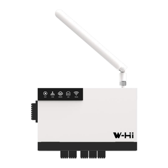
- Page 2 W-HI MANAGER Manuale utente 1 Connessione agli inverter Figura 1 Porta Descrizione POWER Alimentazione Contatti d’ingresso, DRED COM1~3 Porte riservate agli Inverter COM4 Porta per la connessione allo Smart Meter COM5 Porta di connessione a dispositivi Modbus RS485 COM6 Riservato...
-
Page 3: Procedura Consigliata
Più inverter possono essere collegati in stringa. Gli inverter sono interconnessi tramite COM1 e l'ultimo inverter della stringa si collega a COM1/2/3 sul W-Hi Manager. Si consiglia di collegare A ad A e B a B. La connessione massima è fino a 16 per COM. - Page 4 Lato inverter, la porta da utilizzare è la COM1, dove solitamente viene collegata la W-Hi Stick, che in presenza del W-Hi Manager deve essere rimossa. I pin del connettore da utilizzare per le connessioni sono il 3 (A) e 4 (B), e devono essere parallelati come in figura 5.
- Page 5 Questi devono essere lasciati con le loro impostazioni di default: indirizzo Modbus 1 e 9600 di Baudrate e vanno collegati alla porta COM4. Porta Descrizione COM4 Porta per la connessione dello Smart Meter 1. Utilizzare conduttori a doppino intrecciato schermati standard RS485 2.Collegare solo tramite la COM4 sul W-Hi Manager...
- Page 6 W-HI MANAGER Manuale utente 1.4 Connessione ad Ethernet Inserire il connettore RJ45 del cavo di rete nella porta Ethernet finché questo non resta fermo in posizione. 2. Collegare l'altra estremità del cavo di rete a una sorgente di rete, ad es. un router o access point.
- Page 7 Una volta completato l’aggiornamento il dispositivo si riavvierà per cui sarà necessario riconnettersi alla rete WiFi del dispositivo per continuare con la configurazione. N.B. è necessario che il W-Hi Manager abbia l’accesso a internet per effettuare l’aggiornamento. Non viene mostrato il progresso dell’aggiornamento, attendere il tempo indicato all’avvio dell’aggiornamento e poi effettuare un refresh della pagina finché...
- Page 8 W-HI MANAGER Manuale utente 2.2 Scansione degli inverter Spostarsi nella pagina “Elenco dispositivi” (figura 8) e verificare che gli inverter siano stati riconosciuti nella lista. In caso contrario, cliccare sul “Scansione automatica degli inverter” per resettare la lista e rieseguire la scansione.
- Page 9 2.4 Configurazione del meter per impianti fotovoltaici pre-esistenti In caso di impianto fotovoltaico pre-esistente, è possibile integrare la misura della produzione nel monitoraggio del W-Hi Manager utilizzando un secondo meter posto subito a valle dell’impianto pre-esistente. In caso di meter Modbus RS485 (Eastron), questo va collegato alla porta COM5, poi In caso di meter Ethernet (Gavazzi), è...
- Page 10 W-HI MANAGER Manuale utente 3 FAQ • Non posso collegare il dispositivo alla rete tramite Ethernet, è possibile utilizzare il Wi-Fi? Sì, è possibile configurare il Wi-Fi dalla scheda impostazioni di rete, scorrendo in basso, nella sezione “Reti Wi-Fi” si può effettuare una scansione e la connessione a una rete Wi-Fi esistente.
- Page 11 Il prodotto difettoso dovrà essere rispedito alla Western CO. srl o a società delegata dalla Western CO. srl a fare assistenza sul prodotto, a spese del cliente, assieme ad una copia della fattura di vendita, sia per la riparazione che la sostituzione garantita.
- Page 12 W-Hi Manager MANUALE UTENTE V1.2...
- Page 13 W-HI MANAGER User Manual 1 Connection to inverters Figure 1 Door Description POWER Power supply Input Contacts, DRED COM1~3 Ports reserved for Inverters COM4 Port for connecting to the Smart Meter COM5 Connection port to RS485 Modbus devices COM6 Reserved...
-
Page 14: Best Practice
Multiple inverters can be connected in string. The inverters are interconnected via their COM1 and the last inverter in the string connects to COM1/2/3 on the W-Hi Manager. It is recommended to connect A to A and B to B. The maximum connection is up to 16 per COM. - Page 15 On the inverter side, the port to be used is COM1, where the W-Hi Stick is usually connected, which must be removed in the presence of the W-Hi Manager. The connector pins to be used for connections are 3 (A) and 4 (B), and must be paralleled as in figure 5.
- Page 16 These must be left with their default settings: Modbus 1 and 9600 address of Baudrate and must be connected to the COM4 port. Door Description COM4 Smart Meter connection port 1. Use standard RS485 shielded twisted pair conductors 2.Connect only via the COM4 on the W-Hi Manager...
-
Page 17: Connecting To Ethernet
W-HI MANAGER User Manual 1.4 Connecting to Ethernet Plug the RJ45 connector on the network cable into the Ethernet port until it stays in place. 2. Connect the other end of the network cable to a network source, such as a router or access point. - Page 18 WiFi network to continue with the configuration. N.B. the W-Hi Manager must have internet access to perform the update. The progress of the update is not shown, wait for the indicated time when the update starts and then refresh the page until the new interface is displayed.
- Page 19 W-HI MANAGER User Manual 2.2 Inverter scanning Move to the "Device List" page (Figure 8) and check that the inverters have been recognized in the list. If not, click on the "Automatic inverter scan" button to reset the list and rescan.
-
Page 20: Meter Configuration
2.4 Meter configuration for existing PV systems In the case of a pre-existing photovoltaic system, it is possible to integrate the production measurement into the monitoring of the W-Hi Manager using a second meter located immediately downstream of the pre-existing system. - Page 21 W-HI MANAGER User Manual 3 FAQ • I can't connect the device to the network via Ethernet, can I use Wi-Fi? Yes, you can configure Wi-Fi from the network settings tab, by scrolling down, in the "Wi-Fi Networks" section you can scan and connect to an existing Wi-Fi network.
- Page 22 The defective product must be sent back to Western CO. srl or to a company delegated by Western CO. srl to service the product, at the customer's expense, together with a copy of the sales invoice, both for repair and guaranteed replacement.
Need help?
Do you have a question about the W-Hi Manager and is the answer not in the manual?
Questions and answers