Table of Contents
Advertisement
Quick Links
Advertisement
Table of Contents

Related Manuals for D-Link DXS-3130-28-P


Summary of Contents for D-Link DXS-3130-28-P
- Page 1 Version 1.00 | 05/13/2024...
-
Page 2: Table Of Contents
DXS-3130-28-P Layer 3 Stackable Managed Switch Hardware Installation Guide Table of Contents Intended Readers ................................ 6 Typographical Conventions ............................6 Notes and Cautions ..............................6 Safety/Sécurité ................................6 Safety Instructions ............................... 6 Safety Cautions ..............................6 Consignes de sécurité ..............................8 Précautions de sécurité... - Page 3 DXS-3130-28-P Layer 3 Stackable Managed Switch Hardware Installation Guide Web User Interface (Web UI) ............................. 35 Areas of the Web UI ............................. 35 Web Pages ................................35 Appendix A - Technical Specifications ........................37 General ..................................37 Physical and Environmental............................37 Performance................................
- Page 4 Information in this document is subject to change without notice. Reproduction in any manner whatsoever, without the written permission of D-Link Corporation, is strictly forbidden. Trademarks used in this text: D-Link and the D-LINK logo are trademarks of D-Link Corporation; Microsoft and Windows are registered trademarks of Microsoft Corporation.
- Page 5 For AC or DC input: 30W/60W per each PoE port, total: 790W (1440W when two PSU are connected) maximum (for DXS- 3130-28P) To reduce potential safety issues, only the AC adapter purchased as an accessory from “D-Link”, or “agency” should be used with the product for further information.
-
Page 6: Intended Readers
DXS-3130-28-P Layer 3 Stackable Managed Switch Hardware Installation Guide Intended Readers The DXS-3130-28P Layer 3 Stackable Managed Switch Hardware Installation Guide contains detailed information about the hardware specifications of the switches in this series. It also contains brief information on how to configure and manage this switch. - Page 7 DXS-3130-28-P Layer 3 Stackable Managed Switch Hardware Installation Guide • Damage to the power cable, extension cable, or plug. • An object has fallen into the product. • The product has been exposed to water. • The product has been dropped or damaged.
-
Page 8: Consignes De Sécurité
DXS-3130-28-P Layer 3 Stackable Managed Switch Hardware Installation Guide CAUTION: Shock hazard This product is intended to be used with a UL Listed Optical Transceiver product, Rated DC3.3V, Laser Class I. ATTENTION: Risque d'électrocution Ce produit est destiné à être utilisé avec un produit émetteur-récepteur optique répertorié UL, évalué... -
Page 9: General Precautions For Rack-Mountable Products
DXS-3130-28-P Layer 3 Stackable Managed Switch Hardware Installation Guide • Pour éviter tout risque de choc électrique, branchez les câbles d'alimentation du système et des périphériques à des prises électriques correctement mises à la masse. Ces câbles sont équipés de fiches à trois broches pour garantir une mise à... -
Page 10: Protecting Against Electrostatic Discharge
DXS-3130-28-P Layer 3 Stackable Managed Switch Hardware Installation Guide • Use caution when pressing the component rail release latches and sliding a component into or out of a rack; the slide rails can pinch your fingers. • After a component is inserted into a rack, carefully extend the rail to a locking position, and then slide the component into the rack. -
Page 11: Introduction
DXS-3130-28-P Layer 3 Stackable Managed Switch Hardware Installation Guide 1. Introduction This chapter introduces the product descriptions and features of and listed the package contents of the D-Link DXS- 3130-28P switch. Switch Description Package Contents Features Switch Description The D-Link DXS-3130-28P is a high-performance member of the D-Link Layer 3 switch family. Designed to connect... -
Page 12: Features
DXS-3130-28-P Layer 3 Stackable Managed Switch Hardware Installation Guide Features This switch is packed with an abundance of networking features that span inside and outside of the traditional Layer 3 framework. The list below highlights the significant protocols and features supported by this switch. - Page 13 DXS-3130-28-P Layer 3 Stackable Managed Switch Hardware Installation Guide Simple Network Time Protocol (SNTP) IPv4/IPv6 Link Layer Discovery Protocol (LLDP), and LLDP-MED User Account Privilege for Management Access Command Line Interface (CLI) Simple Network Management Protocol (SNMPv1/SNMPv2c/SNMPv3) IPv4/IPv6 Remote Network Monitoring (RMONv1/RMONv2)
-
Page 14: Hardware Components
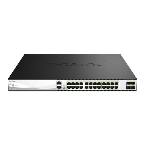
DXS-3130-28-P Layer 3 Stackable Managed Switch Hardware Installation Guide 2. Hardware Components This chapter describes the front, rear, and side panel components of the switch. DXS-3130-28P Switch Front Panel Components The front panel of DXS-3130-28P features a variety of LED indicators and ports. - Page 15 DXS-3130-28-P Layer 3 Stackable Managed Switch Hardware Installation Guide LED status indicator behavior Description Power This LED will light solid green after the Switch has been powered on successfully. This LED will be off when the Switch is no longer receiving power (i.e.
-
Page 16: Rear Panel Components
DXS-3130-28-P Layer 3 Stackable Managed Switch Hardware Installation Guide Please refer to the “LED Indicators” section in the Appendix A - Technical Specifications for more LED information. Rear Panel Components The rear panel of this switch features a GND and two hot-pluggable power supplies. -
Page 17: Side Panel Components
DXS-3130-28-P Layer 3 Stackable Managed Switch Hardware Installation Guide Components on the rear panel of this switch Component Description Switch GND Use an electrical grounding wire and connect one end of the wire to the Switch GND and the other end of the wire to an electrical grounding point most found on the Switch mounting rack itself. -
Page 18: Installation
DXS-3130-28-P Layer 3 Stackable Managed Switch Hardware Installation Guide 3. Installation This chapter covers the installation guidelines and steps and procedures of D-Link DXS-3130-28P switches. Installation Guidelines Installing the Switch without a Rack Installing the Switch in a Standard 19" Rack... -
Page 19: Installing The Switch In A Standard 19" Rack
DXS-3130-28-P Layer 3 Stackable Managed Switch Hardware Installation Guide Installing the Switch in a Standard 19" Rack This section is intended to guide the user through installing the Switch into a switch rack. The Switch can be mounted in a standard 19"(1U) rack using the provided mounting brackets. -
Page 20: Installing Psu Modules Into The Psu Module Slots
Port Functions in Appendix A - Technical Specifications at the end of this document. Installing PSU Modules into the PSU Module Slots Located on the rear panel of the switch, D-Link DXS-3130-28P PSU module slots support the following two PSU modules. AC Power Supply Module: ˙... -
Page 21: Installing Dc Psu Modules
Installing DC PSU Modules D-Link DXS-3130-28P switches support hot-swappable DC PSU modules that you can remove and insert a PSU module when your switch is powered on and in operation. This feature is designed to further ensure and enhance the reliability of your switch. - Page 22 DXS-3130-28-P Layer 3 Stackable Managed Switch Hardware Installation Guide Figure 3-7 Installing a DC Power Supply Module 1. Remove the DC power cord and then press the release clip inwards to remove an existing DC PSU module. 2. Gently pull the DC PSU module out of the PSU module slot.
-
Page 23: Power On (Ac Power)
DXS-3130-28-P Layer 3 Stackable Managed Switch Hardware Installation Guide Power On (AC Power) Plug one end of the AC power cord into the power socket of the Switch and the other end into the local power source outlet. After the system is powered on, the power LED will light up green to indicate that the system has been powered Power Failure (AC Power) In the event of a power failure, just as a precaution, unplug the power cord from the Switch. -
Page 24: Switch Connections
DXS-3130-28-P Layer 3 Stackable Managed Switch Hardware Installation Guide Switch Connections This chapter covers how D-Link DXS-3130-28P switches can switch to different devices such as an end node, another switch, a server, etc. Switch to an End Node Switch to Another Switch... -
Page 25: Switch Stacking
DXS-3130-28-P Layer 3 Stackable Managed Switch Hardware Installation Guide Figure 0-2 Connecting the Switch to another switch/hub Switch Stacking The DXS-3130-28P supports stacking up to 9 switches together while being managed through one console connection on the master switch, or by an IP address through the MGMT port, or by multiple IP addresses through any one of the ports using Telnet, the Web UI, and SNMP. - Page 26 DXS-3130-28-P Layer 3 Stackable Managed Switch Hardware Installation Guide Figure 0-3 Duplex Chain stacking topology (SFP28 ports)
- Page 27 DXS-3130-28-P Layer 3 Stackable Managed Switch Hardware Installation Guide The figures below illustrate how switches can be stacked in a Duplex Ring formation with the last 4 ports of the Switches using optical fiber cables connected to SFP28 transceivers or DAC with SFP28 connectors.
-
Page 28: Switch To A Server
DXS-3130-28-P Layer 3 Stackable Managed Switch Hardware Installation Guide Switch to a Server The Switch is ideal for connecting to a network backbone, server, or server farm. The RJ45 ports operate at a speed of 100/1000 Mbps up to 2.5, 5, or 10 Gbps depending on the model. The SFP28/SFP+ ports operate at a speed of 10 or 25 Gbps. -
Page 29: Switch Management
DXS-3130-28-P Layer 3 Stackable Managed Switch Hardware Installation Guide 4. Switch Management This chapter covers D-Link DXS-3130-28P switches management platform options and how to connect to the different ports respectively. Management Options Connecting to the RJ45 Console Connecting to the Console Port... -
Page 30: Connecting To The Switch For The First Time
DXS-3130-28-P Layer 3 Stackable Managed Switch Hardware Installation Guide To configure the terminal emulation software with the following settings: Select the appropriate serial port (COM1 or COM2). Set the data rate to 115200 baud. Set the data format to 8 data bits, 1 stop bit, and no parity. -
Page 31: Creating A User Account
DXS-3130-28-P Layer 3 Stackable Managed Switch Hardware Installation Guide NOTE: It is highly recommended that you create a user account containing a username and a password for the Switch to prevent unauthorized access to the management interface. Creating a User Account One of the first and most important tasks is to create a user account. -
Page 32: Connecting To The Mgmt Port
DXS-3130-28-P Layer 3 Stackable Managed Switch Hardware Installation Guide 3. Then we entered the VLAN Configuration Mode of the default VLAN, which is VLAN 1, by entering the command, interface vlan 1. 4. Then we changed the IP address of the Switch to 10.50.50.50 and the subnet mask to 255.0.0.0 by entering the command ip address 10.50.50.50 and 255.0.0.0. -
Page 33: Traps
DXS-3130-28-P Layer 3 Stackable Managed Switch Hardware Installation Guide features for proper operation, monitor performance, and detect potential problems in the Switch, switch group, or network. Managed devices that support SNMP include software (referred to as an agent) that runs locally on the device. A defined set of variables (managed objects) is maintained by the SNMP agent and is used to manage the device. -
Page 34: Web-Based Switch Configuration
DXS-3130-28-P Layer 3 Stackable Managed Switch Hardware Installation Guide 5. Web-based Switch Configuration Introduction Logging into the Web UI Web User Interface (Web UI) Introduction Most software functions of the Switch can be managed, configured, and monitored via the embedded HTML Web UI. -
Page 35: Web User Interface (Web Ui)
Switch for the Switch’s ports and expansion modules. It also shows port activity based on a specific mode. Some management functions, including port monitoring, are accessible from here. Click the D-Link logo to go to the D-Link website. AREA 2 This area displays a file explorer-type menu tree with all configurable options. - Page 36 DXS-3130-28-P Layer 3 Stackable Managed Switch Hardware Installation Guide Folder Name Description System Features regarding the Switch’s configuration can be viewed and configured in this folder. Management Features regarding the Switch’s management can be viewed and configured in this folder.
-
Page 37: Appendix A - Technical Specifications
DXS-3130-28-P Layer 3 Stackable Managed Switch Hardware Installation Guide Appendix A - Technical Specifications General Feature Description Data Transfer Rates Standards Full-duplex Ethernet 20 Mbps Fast Ethernet 200 Mbps Gigabit Ethernet 2 Gbps 2.5 Gigabit Ethernet 5 Gbps 5 Gigabit Ethernet... -
Page 38: Performance
DXS-3130-28-P Layer 3 Stackable Managed Switch Hardware Installation Guide Feature Description USB Slot Supports a USB 2.0 Type-A flash drive with a maximum current of 1 A. This slot only supports FAT16 and FAT32 file system architectures. Max: Power Consumption •... - Page 39 DXS-3130-28-P Layer 3 Stackable Managed Switch Hardware Installation Guide Location Color Status Description Light off Operating normally Green Light on (Solid) RPS in use Light off RPS off Green Light on (Solid) USB plugged in Light blinking Busy reading/writing Light off...
-
Page 40: Port Functions
DXS-3130-28-P Layer 3 Stackable Managed Switch Hardware Installation Guide Port Functions Feature Description RJ45 Ports Compliant with the following standards: • IEEE 802.3 compliance • IEEE 802.3u compliance • IEEE 802.3ab compliance • IEEE 802.3an compliance • IEEE 802.3az compliance (Energy Efficient Ethernet) •... -
Page 41: Appendix B - Cables And Connectors
DXS-3130-28-P Layer 3 Stackable Managed Switch Hardware Installation Guide Appendix B - Cables and Connectors Ethernet Cable When connecting the Switch to another switch, a bridge or hub, a straight-through Cat5/5e/6a/7 cable is required. Please refer to these products for matching cable pin assignment. -
Page 42: Console Cable (Rj45 To Rs-232)
DXS-3130-28-P Layer 3 Stackable Managed Switch Hardware Installation Guide Console Cable (RJ45 to RS-232) A console cable is used to connect to the RJ45 console port of the Switch to access the command line interface. The following diagram and table show the standard RJ45 to RS-232 cable and pin assignments. -
Page 43: Ce Red Compliance Statement
DXS-3130-28-P Layer 3 Stackable Managed Switch Hardware Installation Guide CE RED Compliance Statement Additional Notice This equipment should be installed and operated with minimum distance 20 cm between the radiator & your body. -
Page 44: Appendix C - Warranty & Technical Support
If a material defect is incapable of correction, or if D-Link determines that it is not practical to repair or replace the defective Hardware, the actual price paid by the original purchaser for the defective Hardware will be refunded by D-Link upon return to D-Link of the defective Hardware. All Hardware or part thereof that is replaced by D-Link, or for which the purchase price is refunded, shall become the property of D-Link upon replacement or refund. - Page 45 UPS Ground or any common carrier selected by D-Link. Return shipping charges shall be prepaid by D-Link if you use an address in the United States, otherwise we will ship the product to you freight collect. Expedited shipping is available upon request and provided shipping charges are prepaid by the customer.
- Page 46 Copyright Statement: No part of this publication or documentation accompanying this product may be reproduced in any form or by any means or used to make any derivative such as translation, transformation, or adaptation without permission from D-Link Corporation/D-Link Systems, Inc., as stipulated by the United States Copyright Act of 1976 and any amendments thereto.
Need help?
Do you have a question about the DXS-3130-28-P and is the answer not in the manual?
Questions and answers