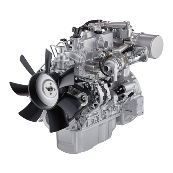
Isuzu 4LE2 Workshop Manual
Diesel engine
Hide thumbs
Also See for 4LE2:
- Owner's manual (107 pages) ,
- Instruction manual (48 pages) ,
- Workshop manual (121 pages)
Table of Contents
Advertisement
Quick Links
Advertisement
Chapters
Table of Contents

Related Manuals for Isuzu 4LE2


Summary of Contents for Isuzu 4LE2
- Page 1 4LE2 TIER 4/STAGE Ⅲ B EXHAUST EMISSION STANDARDS WORKSHOP MANUAL ENGINE...
- Page 2 FOREWORD This manual describes the service procedures for the 4LE2 diesel engine (Tier 4/Stage Ⅲ B compatible). The contents of this manual are current at the date of issue, but may differ slightly from your engine due to specification changes or other modifications made thereafter. This manual consists of the following sub-sections. Publication No. Publication Name Sub-sections IDE-2650 ENGINE Introduction Service Information Guide Maintenance Information Functional Inspection Sympton DTC Information Engine Control Mechanical Fuel System Cooling Lubrication Induction Exhaust Aux. Emission Control Devices Electrical – Wiring Diagram...
- Page 4 Introduction (All models) 0-1 Introduction Introduction (All models) Table of Contents Introduction................0-2 safety information............0-2...
- Page 5 0-2 Introduction (All models) Introduction safety information ・ Prepare the tools, instruments, and special tools in advance. Repair work safety information ・ Prepare the parts that require replacement and Warning: parts that cannot be reused in advance. ・ Workshop manuals are created for qualified ・...
- Page 6 Introduction (All models) 0-3 ・ Make sure the ground connection for the ・ When disconnecting the waterproof connector, welding machine is as close to the welding remove dust or moisture adhering to the area as possible. connector by blowing it with air, etc. If dust or moisture enters the connector, Replacement parts and parts number safety remove it before connecting the connector.
- Page 7 0-4 Introduction (All models) Warning: Caution: ・ If the fuse blows out, identify the cause and ・ When installing electronic parts, take care to replace with a known good fuse of the same ensure the harnesses do not get pinched and capacity.
- Page 8 Introduction (All models) 0-5 1. Clip 1. Existing harness (With protective material) 2. Protective tube 2. Additional harness 3. Band clip for securing harness Caution: 4. Prohibited area for securing band clip ・ For wiring between the engine and chassis, Commercial electronic products safety information give the wiring sufficient free length to prevent wear and damage caused by vibration.
-
Page 10: Table Of Contents
Service Information Guide (All models) 14A-1 Description General Information Service Information Guide (All models) Table of Contents Contents included in service information.....14A-2 Plastic gauge..............14A-4 Recommended liquid gasket.........14A-6 Thread locking adhesive agent........14A-8 Term................14A-9 Abbreviations .............14A-10 Standard bolts..............14A-14... -
Page 11: Contents Included In Service Information
14A-2 Service Information Guide (All models) Contents included in service information Contents included in service information Includes the maintenance precautions specific to each item. Removal Includes the removal procedure for repairing parts, Disconnection devices, etc. Includes the disconnection procedures for wiring, piping, etc. - Page 12 Service Information Guide (All models) 14A-3 1. Vehicle front 9. Gas or warm air 2. Upward 10. Mixing of outside air and gas or mixing of cold 3. Operating section or operating direction air and warm air 4. Detail of a particular part 11.
-
Page 13: Plastic Gauge
14A-4 Service Information Guide (All models) Plastic gauge Using the plasti-gauge Type Measurable range : 0.025 to 0.076 mm { 0.00098 PG-1 (Green) to 0.00299 in } : 0.051 to 0.152 mm { 0.00201 PR-1 (Red) to 0.00598 in } :... - Page 14 Service Information Guide (All models) 14A-5...
-
Page 15: Recommended Liquid Gasket
14A-6 Service Information Guide (All models) Recommended liquid gasket Using the thread liquid gasket Manufacturer Type Product name Area used (reference) name ThreeBond 1207B ThreeBond Engine oil seal retainer Silicon type ThreeBond 1207C ThreeBond Engine oil pan (Room temperature ThreeBond 1215 ThreeBond Timing gear case vulcanization process) - Page 16 Service Information Guide (All models) 14A-7 Caution: ・ If the workshop manual specifies an application method, follow that method.
-
Page 17: Thread Locking Adhesive Agent
14A-8 Service Information Guide (All models) Thread locking adhesive agent Using the thread locking adhesive agent Type Color Loctite 242 Blue Loctite 262 Loctite 271 Caution: ・ Thoroughly remove grime, moisture, oil, and grease from the bolts, bolt holes, and screw thread portion of the nuts to which thread locking adhesive agent will be applied. -
Page 18: Term
Service Information Guide (All models) 14A-9 Term Term Specified value Refers to specified values for inspection, adjustment, assembly, and installation. Limit Refers to a maximum or minimum value that should not be exceeded during maintenance work. If this value is exceeded, the relevant part must be replaced or repaired. -
Page 19: Abbreviations
14A-10 Service Information Guide (All models) Abbreviations Abbreviations... - Page 20 Service Information Guide (All models) 14A-11 Abbreviation Description Analog/Digital ABDC After bottom dead center Alternating current Accessory Alternating current generator Actuator American Petroleum Industry Assembly ATDC After top dead center Automatic transmission fluid Battery + terminal Battery BBDC Before bottom dead center Bracket Bearing BTDC...
- Page 21 HO2S Superheat O2 sensor Idle air control Intake air temperature Integrated circuit ID Plate Name plate (ID Plate) IDSS ISUZU Diagnostic Service System Intake manifold temperature Intake Injection International Organization for Standardization Intake shutter position Intake throttle position Joint connector...
- Page 22 Service Information Guide (All models) 14A-13 Right side Relay Random access memory Reference Read-only memory Rail pressure Rear Rear Rear Society of Automotive Engineers Slow blow fuse FRP regulator Signal Shield Starter/Start Standards Switch Top dead center TEMP Temperature Throttle position Battery voltage VGS Turbo Variable geometry system turbo...
-
Page 23: Standard Bolts
14A-14 Service Information Guide (All models) Standard bolts List of standard bolt and nut tightening torques Note: ・ The tightening torque values in the following table apply to locations where no tightening torque is specified. - Page 24 Service Information Guide (All models) 14A-15 Strength category Bolt head Hex bolt Flange bolt Hex bolt Flange bolt shape : 3.9 to 7.8 N・m { 0.4 to : 4.6 to 8.5 N・m { 0.5 to : 4.9 to 9.8 N・m { 0.5 to :...
- Page 25 14A-16 Service Information Guide (All models) : 358.9 to 539.4 N・m : 430.5 to 711.0 N・m M24 x 2 { 36.6 to 55.0 kgf・m / ― { 43.9 to 72.5 kgf・m / ― 265 to 398 lb・ft } 318 to 524 lb・ft } :...
- Page 26 Service Information Guide (All models) 14A-17 Strength category Bolt head Hex bolt Flange bolt Hex bolt Flange bolt shape : 5.6 to 11.2 N・m { 0.6 : 6.6 to 12.2 N・m { 0.7 M6 x 1 to 1.1 kgf・m / 50 to 99 to 1.2 kgf・m / 58 to 108 ―...
- Page 27 14A-18 Service Information Guide (All models) : 490.8 to 810.5 N・m : 554.1 to 830.6 N・m M24 x 2 { 50.0 to 82.6 kgf・m / ― { 56.5 to 84.7 kgf・m / ― 362 to 598 lb・ft } 409 to 613 lb・ft } :...
- Page 28 Service Information Guide (All models) 14A-19 Flare nut width across Tightening torque for middle- and large-sized flats Pipe diameter vehicles : 12.8 to 18.6 N・m { 1.3 to 1.9 kgf・m / 9 to : 14 mm : 14 mm : 4.6 mm { 0.181 in } 14 lb・ft } { 0.55 in } { 0.55 in }...
- Page 30 Maintenance Information (4LE2) 15B-1 Description Engine Maintenance Information (4LE2) Table of Contents Maintenance precautions..........15B-2 Primary specifications...........15B-5 Function, Structure, Operation........15B-8 Introduction to the trouble diagnosis......15B-48...
-
Page 31: Maintenance Precautions
15B-2 Maintenance Information (4LE2) Maintenance precautions Maintenance precautions Important precautions for handling the engine The holes and gaps in the fuel system, including inside Precautions on maintenance the injector where the fuel passes through, are To prevent the engine from being damaged and to ensure manufactured with high precision. - Page 32 Maintenance Information (4LE2) 15B-3 Aftermarket electronic equipment refers to commercially ・ To prevent damage due to electrostatic available electronic equipment attached to the machine discharge, do not open the packaging of a after it has been shipped from the factory. Be careful, as...
- Page 33 15B-4 Maintenance Information (4LE2) Items to check before programming When performing programming, check the ECM part No. as necessary. When performing programming, check the engine type as necessary. When performing programming, check the engine No. as necessary. When performing programming, check the injector ID code as necessary.
-
Page 34: Primary Specifications
Maintenance Information (4LE2) 15B-5 Primary specifications Primary specifications Engine main specifications... - Page 35 15B-6 Maintenance Information (4LE2) Item Engine model 4LE2 Type Diesel/4-cycle/water-cooled, inline 4 cylinder overhead valve Shape of combustion chamber Direct injection type Cylinder liner type No liner Cylinder bore x stroke 85 mm {3.35 in} × 96 mm {3.78 in} Displacement 2.179 L {133 cu in}...
- Page 36 Maintenance Information (4LE2) 15B-7 Primary specifications of cooling system Item Specifications Water pump Centrifugal impeller method Thermostat Wax pellet type : 82 ℃ { 180 °F } With jiggle valve Open valve temperature : 95 ℃ { 203 °F } With jiggle valve...
-
Page 37: Function, Structure, Operation
15B-8 Maintenance Information (4LE2) Function, Structure, Operation Engine number 1. Engine type stamping 2. Engine number stamping Function, Structure, Operation Crankshaft Do not reuse the crankshaft by grinding, as it has a Description of functions and operations tufftriding surface treatment applied. If a problem is Engine electronic control found, replace with a new one. - Page 38 Maintenance Information (4LE2) 15B-9 pressure fuel, and the fuel injector that injects the fuel in water, and notifies the operator through the indicator the form of a fine mist. Each of these is controlled by the when it becomes full of water.
- Page 39 15B-10 Maintenance Information (4LE2) 1. FRP sensor 2. Pressure limiter Fuel supply pump...
- Page 40 Maintenance Information (4LE2) 15B-11 1. Fuel temperature sensor 4. Camshaft key 2. Suction control valve 3. High pressure pipe Caution: ・ There is a gauze filter assembled inside the union of the fuel supply pump, but the union should not be removed so as to prevent any...
- Page 41 15B-12 Maintenance Information (4LE2) 1. ID plate 2. 2D barcode 3. Injector 4. Fuel inlet Fuel filter 1. Union 2. Gauze filter 3. Supply pump 4. Strainer 5. Joint bolt Injector 1. Priming pump 2. Plug 3. Case 4. Drain plug...
- Page 42 Maintenance Information (4LE2) 15B-13 1. Thermostat 6. Water pump 2. Oil cooler 7. Radiator 3. EGR cooler 8. Bypass pathway 4. Cylinder head 5. Cylinder block Water pump The water pump is a centrifugal impeller type pump and is driven by the engine fan belt.
- Page 43 15B-14 Maintenance Information (4LE2) 1. Fan center 4. Bearing unit 2. Impeller 3. Seal unit Thermostat of 82°C {180°F}, and it is assembled inside the The thermostat is a wax pellet type. The unit is the thermostat housing unit. bottom bypass type with an initial open valve temperature...
- Page 44 Maintenance Information (4LE2) 15B-15 1. Valve 3. Jiggle valve 2. Piston Lubrication type A full-flow bypass integrated filter element, water cooling oil cooler, and piston coolant oil jet are adopted for the lubrication system.
- Page 45 15B-16 Maintenance Information (4LE2) Exhaust system...
- Page 46 Maintenance Information (4LE2) 15B-17 1. Integrated oxidation catalyst silencer Emission control device The EGR operates when the engine speed, engine coolant temperature, intake temperature, and barometric pressure satisfy certain criteria. Then, the valve opening angle is The EGR system recirculates a part of the exhaust gas to...
- Page 47 15B-18 Maintenance Information (4LE2) 1. EGR cooler 5. ECM 2. Coolant outlet 6. Boost pressure sensor/boost temperature sensor 3. Coolant inlet 4. EGR valve Electrical system In addition, 3 small diodes that are referred to as trio- diode are used to supply the field current.
- Page 48 Maintenance Information (4LE2) 15B-19 Generator (12 V - 35 A) regulator, the bearing, and the pulley. The moving parts The regulator is an integrated solid state type. It is are the roller and the pulley. installed together with the brush holder assembly to the The IC regulator cannot be disassembled, so it should be rear end cover and is embedded in the generator.
- Page 49 15B-20 Maintenance Information (4LE2) Starter system than the pinion, the pinion is caused to turn in reverse, The starter is 24 V/3.2 kW or 12 V/2.0 kW and is a but the pinion just idles due to the one-way clutch reduction type.
- Page 50 Maintenance Information (4LE2) 15B-21 Fuel injection correction The ECM calculates the basic injection quantity based on the signals from the accelerator position sensor, boost sensor, CKP sensor, CMP sensor, etc. At this time, the open or close timing of the SCV and the energizing time...
- Page 51 15B-22 Maintenance Information (4LE2) The ECM calculates the current altitude using signals If the ECM is equipped with an emergency stop function from the barometric pressure sensor. by a high engine coolant temperature, it stops the engine According to conditions such as the current altitude, the when the temperature reaches a set temperature.
- Page 52 Maintenance Information (4LE2) 15B-23 Decrease in engine oil pressure Overrun When the engine oil pressure drops below the specified When the engine speed reaches a specified value, an value, an alarm for the engine oil pressure decrease is alarm for overrun is issued and the engine is stopped.
- Page 53 15B-24 Maintenance Information (4LE2) Injection pressure control second injection is performed when ignition is made. The injection pressure is controlled by regulating the fuel This control for injection timing and injection amount is pressure inside the common rail (fuel rail). The proper performed by regulating the injector.
- Page 54 Maintenance Information (4LE2) 15B-25 1. Electromagnetic pump 9. Various sensors (Accelerator, boost, water 2. Fuel filter temperature) 3. Supply pump 10. CKP sensor 4. FRP sensor 11. CMP sensor 5. Common rail (fuel rail) 12. Fuel tank 6. Pressure limiter 13.
- Page 55 15B-26 Maintenance Information (4LE2) 1. Electromagnetic pump 6. Fuel tank 2. Fuel filter 7. Fuel return pipe 3. Supply pump 8. Pre-fuel filter 4. Common rail (fuel rail) 5. Fuel injector Fuel filter clog warning function and engine speed maintaining the restricted engine speed at that time.
- Page 56 Maintenance Information (4LE2) 15B-27 1. Supply pump 6. Pre-fuel filter 2. Warning light 7. Electromagnetic pump 3. Monitor 8. Fuel filter pressure sensor 4. Monitor (CAN communication) 9. Main filter 5. Fuel tank 1. First stage 2. Second stage Removing air from the fuel system Wait for approx.
- Page 57 15B-28 Maintenance Information (4LE2) 1. Pre-fuel filter 5. Supply pump 2. Electromagnetic pump 6. Fuel tank 3. Electromagnetic pump equipment machine 4. Fuel filter Darker portions in the diagram represent large valve lift The EGR system recirculates a part of the exhaust gas to...
- Page 58 Maintenance Information (4LE2) 15B-29 1. EGR cooler 5. ECM 2. Coolant outlet 6. Boost pressure sensor/boost temperature sensor 3. Coolant inlet 4. EGR valve Engine operation control There are the following 4 types of operation control instructions, and the selection varies depending on each specification.
- Page 59 15B-30 Maintenance Information (4LE2) Mode map switch control Outer switch Operation mode Control MAP0 MAP1 MAP2 OFF Basic control OFF Fixed rotation control 1 OFF Fixed rotation control 2 Fixed rotation control 3 OFF ON OFF Maximum engine speed restriction control 1...
- Page 60 For verification and questions regarding the The engine speed upper limit varies depending specifications, contact an Isuzu service-related person. on the engine type, the machine specifications, Idle manual control and the engine warm-up condition.
- Page 61 15B-32 Maintenance Information (4LE2) If a CAN controller exists on the machine side Engine speed output to tachometer The ECM outputs the engine speed pulse to the tachometer as a tachometer output. The tachometer displays the engine speed based on the engine speed pulse sent from the ECM.
- Page 62 Maintenance Information (4LE2) 15B-33 The ECM is designed to maintain regulation levels of About ECM functions exhaust gases while obtaining excellent performance and The ECM constantly monitors the information sent from fuel efficiency. The ECM monitors various engine various sensors, and controls the various systems of the functions via sensors such as the CKP sensor.
- Page 63 15B-34 Maintenance Information (4LE2) circuit tests, make sure to use digital multimeter 5-8840-2691-0. Note: ・ Use the ECM with the part No. corresponding to the machine. When performing welding work on the machine, start the work after disconnecting the negative terminal of the battery.
- Page 64 Maintenance Information (4LE2) 15B-35 1. EGR valve 8. Engine speed sensor 2. Boost pressure sensor/boost temperature sensor 9. CKP sensor 3. Engine coolant temperature sensor 10. FRP sensor 4. CMP sensor 11. Glow plug 5. Suction control valve 12. IMT sensor 6.
- Page 65 15B-36 Maintenance Information (4LE2) supply pump, etc. The voltage becomes lower when the resistance is lower, and it becomes higher when the resistance is higher. Note: ・ Do not replace the fuel temperature sensor. When a malfunction is found, replace the supply pump assembly.
- Page 66 Maintenance Information (4LE2) 15B-37 The pressure limiter is activated when the pressure in the to apply it to the injector, and uses it for fuel injection common rail (fuel rail) becomes unusually high so as to quantity control and injection timing control by release the pressure inside the common rail (fuel rail).
- Page 67 15B-38 Maintenance Information (4LE2) are 56 notches spaced 6° apart and a 30° section without notches. Top dead center of cylinder No. 1 can be detected through this section without notches, and a pulse signal is generated. By detecting the section without...
- Page 68 Maintenance Information (4LE2) 15B-39 Note: ・ For the installation position of the accelerator position sensor, refer to the manual of the machine. Barometric pressure sensor The barometric pressure sensor is installed on the machine side, and it replaces the barometric pressure with a voltage signal.
- Page 69 15B-40 Maintenance Information (4LE2) signal. The ECM calculates the vacuum in the fuel filter based on the voltage signal to determine clogging in the fuel filter. Diagnosis light By turning ON the diagnostic switch, the DTC is indicated by flashing.
- Page 70 Maintenance Information (4LE2) 15B-41 Note: The operation can be performed at the engine speed specified for each mode by switching the mode change ・ For the installation position and shape of the switch. diagnostic switch, refer to the manual of the machine.
- Page 71 15B-42 Maintenance Information (4LE2)
- Page 72 Maintenance Information (4LE2) 15B-43 ECM pin assignment...
- Page 73 15B-44 Maintenance Information (4LE2) 81 pin connector...
- Page 74 Maintenance Information (4LE2) 15B-45 Pin No. Pin name Connection PG-POWER ECM power source GND PS-+B Battery power source PG-POWER ECM power source GND PG-POWER ECM power source GND PS-+B Battery power source OS-DIAGL Diagnosis light OS-BOOSTL Boost temperature sensor pilot light...
- Page 75 15B-46 Maintenance Information (4LE2) IS-LOAD Load advance switch signal IS-START Ignition switch start signal IS-MDMAP0 Mode map switch 0 signal IS-MDMAP1 Mode map switch 1 signal IS-MDMAP2 Mode map switch 2 signal IS-DIAG Diagnostic switch signal IS-MEMCL Memory clear switch...
- Page 76 Maintenance Information (4LE2) 15B-47 Pin No. Pin name Connection IA-PFUEL FRP sensor signal IA-THL Fuel temperature sensor signal IA-THW Engine coolant temperature sensor signal SP-5V5 CMP sensor, fuel pressure sensor, EGR position sensor power source OS-OVRL Engine overrun light IA-SCVLO...
-
Page 77: Introduction To The Trouble Diagnosis
15B-48 Maintenance Information (4LE2) Introduction to the trouble diagnosis Introduction to the trouble diagnosis cannot be reproduced. However, the ECM may have recorded the failure. About trouble diagnosis Past malfunctions, past failures The following trouble diagnosis procedure is extremely important to resolve problems of all Middle stage of failure electric/electronic systems. - Page 78 Maintenance Information (4LE2) 15B-49 ・The check sheet assists in onboard diagnosis, repair, 1. Failure symptoms and repair verification at the vehicle servicing station. 2. Failure frequency/failure conditions...
- Page 79 15B-50 Maintenance Information (4LE2) Preliminary inspection When implementing the diagnostic procedures, Visual inspection of engine room carefully make a visual inspection of the engine...
- Page 80 Maintenance Information (4LE2) 15B-51 room. This inspection can often lead to solving a About the diagnostic test performed on the machine problem without taking extra steps. Past failures ・The diagnostic tests of the previous ignition cycle have ・Visually inspect all air hoses for punched holes, cuts, been completed.
- Page 81 15B-52 Maintenance Information (4LE2) Input components ・Turn the ignition switch ON, but the engine OFF. Check the input components to inspect whether there is ・Connect the diagnostic switch. For a machine with an open circuit in the circuit and whether the values are no diagnostic switch, short No.
- Page 82 Maintenance Information (4LE2) 15B-53 procedure. It is also possible to perform the inspection by Check by testing under the conditions given by the referring to the functional diagnosis. customer. When a DTC is diagnosed, verify that the malfunction When the appropriate symptom is not found has been repaired by reproducing the condition that Investigate the complaint in detail.
- Page 83 15B-54 Maintenance Information (4LE2) Item Item Objective Method Clear the previous DTCs. Keep the engine idling Verification of the DTC display to sufficiently warm it up, then perform a racing DTC check after the repair operation with the engine speed raised up to No Load Max., and secure the test conditions.
- Page 84 Maintenance Information (4LE2) 15B-55 Caution: Factory shipment settings Based on the engine serial number, data such as the ECM ・ When conditions such as the running state of injector QR code can be downloaded to the ECM. the machine or the engine, water temperature,...
- Page 85 15B-56 Maintenance Information (4LE2) Data Display Items Unit Reference values Battery Voltage Target Engine Speed Engine Speed Accelerator Pedal Position Sensor 1 (APP1) Accelerator Pedal Position Sensor 2(APP2) Accelerator Pedal Position (APP) % Fuel Rail Pressure Sensor Fuel Rail Pressure Feedback Engine Coolant Temperature Sensor ℃...
- Page 86 Maintenance Information (4LE2) 15B-57 Fuel Filter Pressure Sensor kPa {psi} Turbochager Drive Duty % Target Fuel Injection Quantity mm3/st Start Of Pilot Injection °CA Target Fuel Rail Pressure mPa {psi} Target Turbocharger Position % Target EGR Valve Position % Target Manifold Absolute Pressure...
- Page 88 Functional Inspection (4LE2) 15C-1 Description Engine Functional Inspection (4LE2) Table of Contents Engine compression pressure inspection.......15C-2 Fuel system check............15C-4 Air intake system check..........15C-5 Exhaust system check............15C-6 EGR control system check..........15C-7 Starting system check............15C-8 Glow control system check...........15C-9 OBD system check............15C-11 Inspection of the diagnostic light warning light illumination circuit system...............15C-12...
-
Page 89: Engine Compression Pressure Inspection
15C-2 Functional Inspection (4LE2) Engine compression pressure inspection Engine compression pressure inspection inspection Start the engine. Note: ・ Warm up the engine. Turn OFF the ignition switch. Disconnect the battery ground cable from the battery. Remove the harness connector from the injector. - Page 90 Functional Inspection (4LE2) 15C-3 13. Connect the harness connector to the injector. 14. Connect the battery ground cable to the battery.
-
Page 91: Fuel System Check
15C-4 Functional Inspection (4LE2) Fuel system check Fuel system check description of function The fuel system consists of the fuel tank, fuel filter, supply pump, common rail (fuel rail), and injectors, with each component being connected by the fuel pipe. -
Page 92: Air Intake System Check
Functional Inspection (4LE2) 15C-5 Air intake system check Air intake system check description of function Caution: ・ If the air intake system parts were installed by the machine manufacturer, refer to the machine manual. The air intake system consists of the air cleaner, air intake pipe, turbocharger, and other components. -
Page 93: Exhaust System Check
15C-6 Functional Inspection (4LE2) Exhaust system check Exhaust system check description of function The exhaust system consists of the exhaust pipe, tail pipe, etc. Exhaust system check inspection Inspection when there may be a malfunction in the exhaust system Inspect the exhaust pipe and the tail pipe. -
Page 94: Egr Control System Check
Functional Inspection (4LE2) 15C-7 EGR control system check EGR control system check description of function Refer to "1.Engine 1H.Aux. Emission Control Devices(4LE2) EGR valve installation". The ECM controls the EGR valve based on the engine speed, engine coolant temperature, intake air temperature, fuel injection quantity, and barometric pressure. -
Page 95: Starting System Check
No air should be mixed into the fuel when performing assembly. this diagnostic. The air cleaner element should be clean when performing Refer to "1.Engine 1C.Fuel System(4LE2) Common this diagnostic. rail assembly removal". The fuel filter should be clean when performing this Refer to "1.Engine 1C.Fuel System(4LE2) Common... -
Page 96: Glow Control System Check
Functional Inspection (4LE2) 15C-9 Glow control system check Glow control system check description of function values: 6 Ω At room temperature Caution: Note: ・ For both the starter ECM control specification ・ If the reading is not the specified value, inspect and the safety relay specification, the QOS the applicable glow plug. - Page 97 15C-10 Functional Inspection (4LE2) 21. After replacing the ECM, set the injector ID code.
-
Page 98: Obd System Check
Functional Inspection (4LE2) 15C-11 OBD system check OBD system check description of function ・ If the diagnostic light does not flash, inspect the diagnostic light flashing circuit system. The OBD system check is a systematic method for checking problems caused by a malfunction in the engine... -
Page 99: Inspection Of The Diagnostic Light Warning Light Illumination Circuit System
15C-12 Functional Inspection (4LE2) Inspection of the diagnostic light warning light illumination circuit system Inspection of the diagnostic light warning light illumination circuit system description of function Power supply voltage is provided to the diagnostic light via the ignition switch, and the light illuminates based on the signal from the ECM. -
Page 100: Inspection Of The Diagnostic Light Warning Light Blinking Circuit System
Functional Inspection (4LE2) 15C-13 Inspection of the diagnostic light warning light blinking circuit system Inspection of the diagnostic light warning light 13. Replace the ECM. blinking circuit system description of function Refer to "1.Engine 1J.Electrical(4LE2) Power supply voltage is provided to the diagnostic light ECM removal". -
Page 101: Inspection Of The Starter Circuit System
START position. When the starter 14. Inspect the starter. relay is turned ON, the starter is activated to start the Refer to "1.Engine 1J.Electrical(4LE2) Starter engine. motor inspection". Inspection of the starter circuit system inspection 15. - Page 102 Symptom (4LE2) 15D-1 Description Engine Symptom (4LE2) Table of Contents Engine start failure............15D-2 Engine stalling...............15D-4 Engine hunching, rough idling........15D-6 Excessive white smoke in the exhaust gas....15D-7 Excessive black smoke in the exhaust gas....15D-8 Abnormal noise.............15D-9 Large fuel consumption..........15D-10 Large oil consumption..........15D-12...
-
Page 103: Engine Start Failure
Charges for supply pump replacement due to use of oil blends of fuel after long storage periods and biofuel Isuzu genuine pre-filters have no air removal plug, so containing organic substances will be incurred. check whether the layout may cause air to accumulate. - Page 104 Symptom (4LE2) 15D-3 r/min or less, and the absolute pressure is 15 MPa {153 Decrease in system performance due to a failure kgf/cm2 / 2175 psi} or less, for 3 seconds or more. Malfunctions in the engine body such as seizure,...
-
Page 105: Engine Stalling
Whether structures in the layout of the fuel filter, pre- filter, and electromagnetic pump may cause air to accumulate. Isuzu genuine pre-filters have no air removal plug, so check whether the layout may cause air to accumulate. Also, check whether the layout of the electromagnetic pump inlet and outlet is appropriate. - Page 106 Symptom (4LE2) 15D-5 Malfunctions of the common rail (fuel rail) such as activation of the pressure limiter or internal sealing deterioration Malfunctions in the injector, failure to inject fuel Decrease in system performance due to a failure Malfunctions in the engine body such as seizure,...
-
Page 107: Engine Hunching, Rough Idling
Check for poor connections at the connector and for Isuzu genuine pre-filters have no air removal plug, so malfunctions such as abrasion or bends at the harness. check whether the layout may cause air to accumulate. -
Page 108: Excessive White Smoke In The Exhaust Gas
Symptom (4LE2) 15D-7 Excessive white smoke in the exhaust gas Excessive white smoke in the exhaust gas description Engine body failure such as insufficient compression of symptom pressure, piston related failure, turbocharger failure, or a decrease or increase in oil Heavy white smoke is produced during operation. -
Page 109: Excessive Black Smoke In The Exhaust Gas
15D-8 Symptom (4LE2) Excessive black smoke in the exhaust gas Excessive black smoke in the exhaust gas description of symptom Heavy black smoke is produced during operation. Excessive black smoke in the exhaust gas diagnostics ・Preliminary inspection Before using this section, perform functional inspections or OBD system checks to check the following. -
Page 110: Abnormal Noise
Symptom (4LE2) 15D-9 Abnormal noise Abnormal noise description of symptom and control, etc., of each part. Repair if a malfunction is detected. The engine combustion sound is abnormal. Abnormal noise diagnostics ・Preliminary inspection Before using this section, perform functional inspections or OBD system checks to check the following. -
Page 111: Large Fuel Consumption
15D-10 Symptom (4LE2) Large fuel consumption Large fuel consumption description of symptom Whether the ECM ground is clean and securely installed to the correct position. Fuel consumption is significantly greater than described Cracks and twists in the pipes and hoses related to fuel, in the manual for the machine. - Page 112 Symptom (4LE2) 15D-11 1. Integrated oxidation catalyst silencer 5. From air cleaner 2. Exhaust pipe 6. EGR valve 3. From intercooler 7. EGR cooler 4. To intercooler...
-
Page 113: Large Oil Consumption
15D-12 Symptom (4LE2) Large oil consumption Large oil consumption description of symptom Perform functional diagnostic inspections, and check the operation, control, etc., of each part. Repair if a Oil consumption is significantly greater than described in malfunction is detected. the manual for the machine. -
Page 114: Insufficient Engine Output
Symptom (4LE2) 15D-13 Insufficient engine output Insufficient engine output description of symptom Malfunctions in the fuel system such as no fuel, fuel freezing, air in the fuel pipe, filter malfunctions, pipe The engine output is below the predicted output, the... - Page 116 DTC Information (4LE2 (12V)) 15E-1 Description Engine DTC Information (4LE2 (12V)) Table of Contents DTC P0016 (Flash Code 16) Crankshaft Position - Camshaft DTC P0219 (Flash Code 543) Engine Overspeed Condition Position Correlation............15E-3 ..................15E-24 DTC P0087 (Flash Code 225) Fuel Rail/System Pressure - DTC P0237 (Flash Code 32) Turbocharger Boost Sensor Too Low................15E-4...
- Page 117 15E-2 DTC Information (4LE2 (12V)) DTC P0687 (Flash Code 416) ECM/PCM Power Relay Control Circuit High............15E-46 DTC P0697 (Flash Code 57) Sensor Reference Voltage 3 Circuit................15E-47 DTC P06AF (Flash Code 277) EDU Injector Custom IC,Check Sum,Communication Line......15E-48 DTC P1093 (Flash Code 227) Fuel Rail Pressure (FRP) Too Low................15E-49...
-
Page 118: Position Correlation
DTC Information (4LE2 (12V)) 15E-3 DTC P0016 (Flash Code 16) Crankshaft Position - Camshaft Position Correlation DTC P0016 description of DTC The CKP sensor is installed on the right rear of the cylinder block. The sensor rotor is fixed on the crankshaft. -
Page 119: Dtc P0087 (Flash Code 225) Fuel Rail/System Pressure - Too Low
15E-4 DTC Information (4LE2 (12V)) DTC P0087 (Flash Code 225) Fuel Rail/System Pressure - Too Low DTC P0087 description of DTC A typical common rail (fuel rail) system is composed of the following 2 fuel pressure sections. A suction side between the fuel tank and the supply pump, and a high pressure side between the supply pump and the injectors. -
Page 120: Dtc P0089 (Flash Code 151) Fuel Pressure Regulator Performance
DTC Information (4LE2 (12V)) 15E-5 DTC P0089 (Flash Code 151) Fuel Pressure Regulator Performance DTC P0089 description of DTC A typical common rail (fuel rail) system is composed of the following 2 fuel pressure sections. A suction side between the fuel tank and the supply pump, and a high pressure side between the supply pump and the injectors. -
Page 121: Dtc P0091 (Flash Code 247) Fuel Pressure Regulator Control Circuit Low
15E-6 DTC Information (4LE2 (12V)) DTC P0091 (Flash Code 247) Fuel Pressure Regulator Control Circuit Low DTC P0091 description of DTC The suction control valve is installed on the supply pump and controls the fuel amount sucked into the common rail (fuel rail). -
Page 122: Dtc P0092 (Flash Code 247) Fuel Pressure Regulator Control Circuit High
DTC Information (4LE2 (12V)) 15E-7 DTC P0092 (Flash Code 247) Fuel Pressure Regulator Control Circuit High DTC P0092 description of DTC The suction control valve is installed on the supply pump and controls the fuel amount sucked into the common rail (fuel rail). -
Page 123: Dtc P0093 (Flash Code 227) Fuel System Leak Detected
15E-8 DTC Information (4LE2 (12V)) DTC P0093 (Flash Code 227) Fuel System Leak Detected DTC P0093 description of DTC A typical common rail (fuel rail) system is composed of the following 2 fuel pressure sections. A suction side between the fuel tank and the supply pump, and a high pressure side between the supply pump and the injectors. -
Page 124: Sensor Circuit Low
DTC Information (4LE2 (12V)) 15E-9 DTC P0097 (Flash Code 214) Intake Manifold Temperature Sensor Circuit Low DTC P0097 description of DTC The IMT sensor is installed to the intake chamber. The IMT sensor is a thermistor type sensor and it measures the temperature of the intake air mixed with EGR gas. -
Page 125: Sensor Circuit High
15E-10 DTC Information (4LE2 (12V)) DTC P0098 (Flash Code 214) Intake Manifold Temperature Sensor Circuit High DTC P0098 description of DTC The IMT sensor is installed to the intake chamber. The IMT sensor is a thermistor type sensor and it measures the temperature of the intake air mixed with EGR gas. -
Page 126: Dtc P0112 (Flash Code 22) Intake Air Temperature Sensor Circuit Low
DTC Information (4LE2 (12V)) 15E-11 DTC P0112 (Flash Code 22) Intake Air Temperature Sensor Circuit Low DTC P0112 description of DTC The boost temperature sensor is a thermistor type sensor and it measures the temperature of the air flowing into the engine. -
Page 127: Dtc P0113 (Flash Code 22) Intake Air Temperature Sensor Circuit High
15E-12 DTC Information (4LE2 (12V)) DTC P0113 (Flash Code 22) Intake Air Temperature Sensor Circuit High DTC P0113 description of DTC The boost temperature sensor is a thermistor type sensor and it measures the temperature of the air flowing into the engine. -
Page 128: Sensor Circuit Low
DTC Information (4LE2 (12V)) 15E-13 DTC P0117 (Flash Code 23) Engine Coolant Temperature Sensor Circuit Low DTC P0117 description of DTC The engine coolant temperature sensor is installed in the thermostat housing. The engine coolant temperature sensor is a thermistor type sensor and measures the temperature of the engine coolant. -
Page 129: Sensor Circuit High
15E-14 DTC Information (4LE2 (12V)) DTC P0118 (Flash Code 23) Engine Coolant Temperature Sensor Circuit High DTC P0118 description of DTC The engine coolant temperature sensor is installed in the thermostat housing. The engine coolant temperature sensor is a thermistor type sensor and measures the temperature of the engine coolant. -
Page 130: Dtc P0182 (Flash Code 211) Fuel Temperature Sensor Circuit Low
DTC Information (4LE2 (12V)) 15E-15 DTC P0182 (Flash Code 211) Fuel Temperature Sensor Circuit Low DTC P0182 description of DTC The fuel temperature sensor is installed on the supply pump. The fuel temperature sensor is a thermistor type sensor and measures the temperature of the fuel entering the supply pump. -
Page 131: Dtc P0183 (Flash Code 211) Fuel Temperature Sensor Circuit High
15E-16 DTC Information (4LE2 (12V)) DTC P0183 (Flash Code 211) Fuel Temperature Sensor Circuit High DTC P0183 description of DTC The fuel temperature sensor is installed on the supply pump. The fuel temperature sensor is a thermistor type sensor and measures the temperature of the fuel entering the supply pump. -
Page 132: Dtc P0192 (Flash Code 245) Fuel Rail Pressure Sensor Circuit Low
DTC Information (4LE2 (12V)) 15E-17 DTC P0192 (Flash Code 245) Fuel Rail Pressure Sensor Circuit Low DTC P0192 description of DTC The barometric pressure sensor changes the signal voltage according to changes in the barometric pressure. The sensor has the following circuits. -
Page 133: Dtc P0193 (Flash Code 245) Fuel Rail Pressure Sensor Circuit High
15E-18 DTC Information (4LE2 (12V)) DTC P0193 (Flash Code 245) Fuel Rail Pressure Sensor Circuit High DTC P0193 description of DTC The common rail (fuel rail) pressure sensor is installed to the common rail (fuel rail) and detects the fuel pressure in the common rail (fuel rail) and converts the pressure into a voltage signal. -
Page 134: Dtc P0201 (Flash Code 271) Injector Circuit - Cylinder 1
DTC Information (4LE2 (12V)) 15E-19 DTC P0201 (Flash Code 271) Injector Circuit - Cylinder 1 DTC P0201 description of DTC The ECM calculates the optimum fuel injection ON time based on the data sent from sensors. The injector power supply circuit supplies high voltage, while the ECM grounds the injector solenoid control circuit and drives the injectors of each cylinder. -
Page 135: Dtc P0202 (Flash Code 272) Injector Circuit - Cylinder 2
15E-20 DTC Information (4LE2 (12V)) DTC P0202 (Flash Code 272) Injector Circuit - Cylinder 2 DTC P0202 description of DTC The ECM calculates the optimum fuel injection ON time based on the data sent from sensors. The injector power supply circuit supplies high voltage, while the ECM grounds the injector solenoid control circuit and drives the injectors of each cylinder. -
Page 136: Dtc P0203 (Flash Code 273) Injector Circuit - Cylinder 3
DTC Information (4LE2 (12V)) 15E-21 DTC P0203 (Flash Code 273) Injector Circuit - Cylinder 3 DTC P0203 description of DTC The ECM calculates the optimum fuel injection ON time based on the data sent from sensors. The injector power supply circuit supplies high voltage, while the ECM grounds the injector solenoid control circuit and drives the injectors of each cylinder. -
Page 137: Dtc P0204 (Flash Code 274) Injector Circuit - Cylinder 4
15E-22 DTC Information (4LE2 (12V)) DTC P0204 (Flash Code 274) Injector Circuit - Cylinder 4 DTC P0204 description of DTC The ECM calculates the optimum fuel injection ON time based on the data sent from sensors. The injector power supply circuit supplies high voltage, while the ECM grounds the injector solenoid control circuit and drives the injectors of each cylinder. -
Page 138: Dtc P0217 (Flash Code 542) Engine Coolant Over Temperature Condition
DTC Information (4LE2 (12V)) 15E-23 DTC P0217 (Flash Code 542) Engine Coolant Over Temperature Condition DTC P0217 description of DTC The engine coolant temperature sensor is installed on the thermostat housing. The engine coolant temperature sensor is a thermistor type and measures the temperature of the engine coolant. -
Page 139: Dtc P0219 (Flash Code 543) Engine Overspeed Condition
15E-24 DTC Information (4LE2 (12V)) DTC P0219 (Flash Code 543) Engine Overspeed Condition DTC P0219 description of DTC The CKP sensor is installed on the right rear of the cylinder block. The ECM calculates the engine speed and accurate crankshaft position based on the signal pulse from the CKP sensor. -
Page 140: Dtc P0237 (Flash Code 32) Turbocharger Boost Sensor Circuit Low
DTC Information (4LE2 (12V)) 15E-25 DTC P0237 (Flash Code 32) Turbocharger Boost Sensor Circuit Low DTC P0237 description of DTC The boost pressure sensor is located in the air intake pipe. This sensor changes the signal voltage in accordance with changes in air pressure in the air intake pipe. -
Page 141: Dtc P0238 (Flash Code 32) Turbocharger Boost Sensor Circuit High
15E-26 DTC Information (4LE2 (12V)) DTC P0238 (Flash Code 32) Turbocharger Boost Sensor Circuit High DTC P0238 description of DTC The boost pressure sensor is located in the air intake pipe. This sensor changes the signal voltage in accordance with changes in air pressure in the air intake pipe. -
Page 142: Dtc P0335 (Flash Code 15) Crankshaft Position Sensor Circuit
DTC Information (4LE2 (12V)) 15E-27 DTC P0335 (Flash Code 15) Crankshaft Position Sensor Circuit DTC P0335 description of DTC The CKP sensor is installed on the right rear of the cylinder block. The sensor rotor is fixed on the crankshaft. There are 56 notches spaced 6° apart and a 30°... -
Page 143: Circuit Range/Performance
15E-28 DTC Information (4LE2 (12V)) DTC P0336 (Flash Code 15) Crankshaft Position Sensor Circuit Range/Performance DTC P0336 description of DTC The CKP sensor is installed on the right rear of the cylinder block. The sensor rotor is fixed on the crankshaft. -
Page 144: Dtc P0340 (Flash Code 14) Camshaft Position Sensor Circuit
DTC Information (4LE2 (12V)) 15E-29 DTC P0340 (Flash Code 14) Camshaft Position Sensor Circuit DTC P0340 description of DTC The CMP sensor is installed on the gear case cover. The CMP sensor detects 5 protrusions in total per 1 engine rotation. -
Page 145: Dtc P0380 (Flash Code 66) Glow Plug Circuit
15E-30 DTC Information (4LE2 (12V)) DTC P0380 (Flash Code 66) Glow Plug Circuit DTC P0380 description of DTC The glow relay stops providing power supply voltage to the glow plug, and ON is displayed if the signal from the ECM is entered. The ECM recognizes the ignition switch ON signal, and outputs the ON signal to the glow relay. -
Page 146: Control Circuit Range/Performance
DTC Information (4LE2 (12V)) 15E-31 DTC P0404 (Flash Code 45) Exhaust Gas Recirculation 1 Control Circuit Range/Performance DTC P0404 description of DTC The ECM controls the opening and closing of the EGR valve based on the driving condition of the engine by controlling the EGR solenoid. -
Page 147: Dtc P0409 (Flash Code 44) Exhaust Gas Recirculation 1 Sensor Circuit
15E-32 DTC Information (4LE2 (12V)) DTC P0409 (Flash Code 44) Exhaust Gas Recirculation 1 Sensor Circuit DTC P0409 description of DTC The EGR position sensor is on the EGR valve together with the control solenoid. This sensor is made up of 3 individual sensors within 1 housing. -
Page 148: Dtc P0521 (Flash Code 294) Engine Oil Pressure Sensor Performance
DTC Information (4LE2 (12V)) 15E-33 DTC P0521 (Flash Code 294) Engine Oil Pressure Sensor Performance DTC P0521 description of DTC The oil pressure sensor detects the engine oil pressure. The oil pressure sensor is installed near the oil cooler of the cylinder block. -
Page 149: Dtc P0522 (Flash Code 294) Oil Pressure Sensor Circuit Low Input
15E-34 DTC Information (4LE2 (12V)) DTC P0522 (Flash Code 294) Oil Pressure Sensor Circuit Low Input DTC P0522 description of DTC The oil pressure sensor detects the engine oil pressure. The oil pressure sensor is installed near the oil cooler of the cylinder block. -
Page 150: Dtc P0523 (Flash Code 294) Oil Pressure Sensor Circuit High Input
DTC Information (4LE2 (12V)) 15E-35 DTC P0523 (Flash Code 294) Oil Pressure Sensor Circuit High Input DTC P0523 description of DTC The oil pressure sensor detects the engine oil pressure. The oil pressure sensor is installed near the oil cooler of the cylinder block. -
Page 151: Dtc P0563 (Flash Code 35) System Voltage High
15E-36 DTC Information (4LE2 (12V)) DTC P0563 (Flash Code 35) System Voltage High DTC P0563 description of DTC The ECM monitors the ignition voltage on the ignition feed terminal to verify that the voltage stays within the proper range. If the ECM detects that the voltage of the ignition power source is abnormally high, the DTC is set. -
Page 152: Memory Check Sum Error
DTC Information (4LE2 (12V)) 15E-37 DTC P0601 (Flash Code 53) Internal Control Module Memory Check Sum Error DTC P0601 description of DTC This diagnosis applies to the microprocessor inside the ECM. DTC P0601 condition for setting the DTC The ECM detects that the calculated checksum does not agree with the ROM internal registered checksum. -
Page 153: Dtc P0602 (Flash Code 154) Control Module Programming Error
15E-38 DTC Information (4LE2 (12V)) DTC P0602 (Flash Code 154) Control Module Programming Error DTC P0602 description of DTC The injector ID code and the fuel delivery rate data is stored in the EEPROM within the ECM. If no injector ID... -
Page 154: Random Access Memory (Ram)
DTC Information (4LE2 (12V)) 15E-39 DTC P0604 (Flash Code 153) Internal Control Module Random Access Memory (RAM) DTC P0604 description of DTC This diagnosis applies to the microprocessor inside the ECM. DTC P0604 condition for setting the DTC The battery voltage is 8 V or more. -
Page 155: Dtc P0606 (Flash Code 51) Ecm/Pcm Processor
15E-40 DTC Information (4LE2 (12V)) DTC P0606 (Flash Code 51) ECM/PCM Processor DTC P0606 description of DTC This diagnosis applies to the microprocessor inside the ECM. DTC P0606 condition for setting the DTC The battery voltage is 8 V or more. -
Page 156: Processing Performance
DTC Information (4LE2 (12V)) 15E-41 DTC P060B (Flash Code 36) Internal Control Module A/D Processing Performance DTC P060B description of DTC This diagnosis applies to the microprocessor inside the ECM. DTC P060B condition for setting the DTC The ECM detects a malfunction of the internal A/D converter. -
Page 157: Dtc P0615 (Flash Code 19) Starter Relay Circuit
15E-42 DTC Information (4LE2 (12V)) DTC P0615 (Flash Code 19) Starter Relay Circuit DTC P0615 description of DTC The starter cut switch is provided to prevent the starter from operating when the engine is running. The starter cut relay is a normal closed relay and is positioned between the main relay and starter relay. -
Page 158: Dtc P0641 (Flash Code 55) Sensor Reference Voltage 1 Circuit
DTC Information (4LE2 (12V)) 15E-43 DTC P0641 (Flash Code 55) Sensor Reference Voltage 1 Circuit DTC P0641 description of DTC The ECM supplies 5 V power to the following sensors through power supply circuit 1. Accelerator position sensor Fuel filter pressure sensor... -
Page 159: Dtc P0651 (Flash Code 56) Sensor Reference Voltage 2 Circuit
15E-44 DTC Information (4LE2 (12V)) DTC P0651 (Flash Code 56) Sensor Reference Voltage 2 Circuit DTC P0651 description of DTC The ECM supplies 5 V power to the following sensor through 5 V power supply circuit 2. Barometric pressure sensor The ECM also supplies 5 V power to the following sensors through 5 V power supply circuit 5. -
Page 160: Control Circuit/Open
DTC Information (4LE2 (12V)) 15E-45 DTC P0685 (Flash Code 416) ECM/PCM Power Relay Control Circuit/Open DTC P0685 description of DTC The ECM main relay is applied to supply the battery power to the ECM through the relay switch side when the ECM receives an ignition switch ON signal. -
Page 161: Dtc P0687 (Flash Code 416) Ecm/Pcm Power Relay Control Circuit High
15E-46 DTC Information (4LE2 (12V)) DTC P0687 (Flash Code 416) ECM/PCM Power Relay Control Circuit High DTC P0687 description of DTC The ECM main relay is applied to supply the battery power to the ECM through the relay switch side when the ECM receives an ignition switch ON signal. -
Page 162: Dtc P0697 (Flash Code 57) Sensor Reference Voltage 3 Circuit
DTC Information (4LE2 (12V)) 15E-47 DTC P0697 (Flash Code 57) Sensor Reference Voltage 3 Circuit DTC P0697 description of DTC The ECM supplies 5 V power to the following sensors through power supply circuit 3. Oil pressure sensor The ECM monitors the voltage of 5 V power supply circuit 3, and if it detects that the voltage is abnormally low or high, the DTC is set. -
Page 163: Ic,Check Sum,Communication Line
15E-48 DTC Information (4LE2 (12V)) DTC P06AF (Flash Code 277) EDU Injector Custom IC,Check Sum,Communication Line DTC P06AF description of DTC This diagnosis applies to the injector IC inside the ECM. DTC P06AF condition for setting the DTC Note: ・ Injector IC malfunction The engine is running. -
Page 164: Dtc P1093 (Flash Code 227) Fuel Rail Pressure (Frp) Too Low
DTC Information (4LE2 (12V)) 15E-49 DTC P1093 (Flash Code 227) Fuel Rail Pressure (FRP) Too Low DTC P1093 description of DTC A typical common rail (fuel rail) system is composed of the following 2 fuel pressure sections. A suction side... -
Page 165: Dtc P1097 (Flash Code 213) Boost Temperature Sensor Circuit Low
15E-50 DTC Information (4LE2 (12V)) DTC P1097 (Flash Code 213) Boost Temperature Sensor Circuit Low DTC P1097 description of DTC The boost temperature sensor is installed in the intake chamber. The boost temperature sensor changes its resistance according to the temperature in the intake chamber. -
Page 166: Dtc P1098 (Flash Code 213) Boost Temperature Sensor Circuit High
DTC Information (4LE2 (12V)) 15E-51 DTC P1098 (Flash Code 213) Boost Temperature Sensor Circuit High DTC P1098 description of DTC The boost temperature sensor is installed in the intake chamber. The resistance changes according to the temperature in the intake chamber. The resistance becomes lower when the intake air temperature is high, and higher when the intake air temperature is low. -
Page 167: Dtc P1261 (Flash Code 34) Fuel Injector Group 1 Supply Voltage Circuit
15E-52 DTC Information (4LE2 (12V)) DTC P1261 (Flash Code 34) Fuel Injector Group 1 Supply Voltage Circuit DTC P1261 description of DTC The charge voltage circuit inside the ECM increases the voltage applied to the injector. The charge voltage circuit is divided into two banks: common power supply 1 and common power supply 2. -
Page 168: Dtc P1262 (Flash Code 34) Fuel Injector Group 2 Supply Voltage Circuit
DTC Information (4LE2 (12V)) 15E-53 DTC P1262 (Flash Code 34) Fuel Injector Group 2 Supply Voltage Circuit DTC P1262 description of DTC The charge voltage circuit inside the ECM increases the voltage applied to the injector. The charge voltage circuit is divided into two banks: common power supply 1 and common power supply 2. -
Page 169: Closed Position Performance
15E-54 DTC Information (4LE2 (12V)) DTC P1404 (Flash Code 45) Exhaust Gas Recirculation 1 Closed Position Performance DTC P1404 description of DTC The ECM controls the opening and closing of the EGR valve based on the driving condition of the engine by controlling the EGR solenoid. -
Page 170: Dtc P1606 (Flash Code 51) Sw-Ic 1 Internal
DTC Information (4LE2 (12V)) 15E-55 DTC P1606 (Flash Code 51) SW-IC 1 Internal failure,Communication line failure DTC P1606 description of DTC This diagnosis applies to the SW-IC1 inside the ECM. DTC P1606 condition for setting the DTC Note: ・ SW-IC internal malfunction A malfunction in the SW-IC circuit was detected. -
Page 171: Dtc P160B (Flash Code 36) Ad-Ic Failure
15E-56 DTC Information (4LE2 (12V)) DTC P160B (Flash Code 36) AD-IC failure DTC P160B description of DTC This diagnosis applies to the AD-IC inside the ECM. DTC P160B condition for setting the DTC The battery voltage is between 8 - 16 V. -
Page 172: Memory Performance
DTC Information (4LE2 (12V)) 15E-57 DTC P1621 (Flash Code 54) Control Module Long Term Memory Performance DTC P1621 description of DTC This diagnosis applies to the microprocessor inside the ECM. DTC P1621 condition for setting the DTC The ignition switch is ON. -
Page 173: Dtc P1655 (Flash Code 59) Sensor Reference Voltage 4 Circuit
15E-58 DTC Information (4LE2 (12V)) DTC P1655 (Flash Code 59) Sensor Reference Voltage 4 Circuit DTC P1655 description of DTC The ECM supplies 5 V power to the following sensors through power supply circuit 4. CKP sensor The ECM monitors the voltage of 5 V power supply circuit 4, and if it detects that the voltage is abnormally low or high, the DTC is set. -
Page 174: Dtc P2146 (Flash Code 158) Fuel Injector Group 1 Supply Voltage Circuit
DTC Information (4LE2 (12V)) 15E-59 DTC P2146 (Flash Code 158) Fuel Injector Group 1 Supply Voltage Circuit DTC P2146 description of DTC The ECM calculates the optimum fuel injection ON time based on the data sent from various sensors. The injector... -
Page 175: Dtc P2149 (Flash Code 159) Fuel Injector Group 2 Supply Voltage Circuit
15E-60 DTC Information (4LE2 (12V)) DTC P2149 (Flash Code 159) Fuel Injector Group 2 Supply Voltage Circuit DTC P2149 description of DTC The ECM calculates the optimum fuel injection ON time based on the data sent from sensors. The injector charge... -
Page 176: Dtc P2228 (Flash Code 71) Barometric Pressure Circuit Low
DTC Information (4LE2 (12V)) 15E-61 DTC P2228 (Flash Code 71) Barometric Pressure Circuit Low DTC P2228 description of DTC The barometric pressure sensor changes the signal voltage according to changes in the barometric pressure. The sensor has the following circuits. -
Page 177: Dtc P2229 (Flash Code 71) Barometric Pressure Circuit High
15E-62 DTC Information (4LE2 (12V)) DTC P2229 (Flash Code 71) Barometric Pressure Circuit High DTC P2229 description of DTC The barometric pressure sensor changes the signal voltage according to changes in the barometric pressure. The sensor has the following circuits. -
Page 178: Circuit Or Up/Down Switch Error
DTC Information (4LE2 (12V)) 15E-63 DTC P256A (Flash Code 31) Idle Up Volume Sensor Circuit Or Up/Down Switch Error DTC P256A description of DTC The idling control switch is a switch for adjusting the idling rpm speed during warm-up and can be used when the idling control selector switch is set to "manual". -
Page 179: Dtc U0073 (Flash Code 84) Can-Bus Malfunction (J1939)
15E-64 DTC Information (4LE2 (12V)) DTC U0073 (Flash Code 84) CAN-Bus Malfunction (J1939) DTC U0073 description of DTC The ECM communicates with the control unit of the machine via the CAN communication circuit. The ECM outputs data via the CAN-High circuit and inputs data from other ECUs via the CAN-Low circuit. -
Page 180: Dtc Mapping Table
DTC Information (4LE2 (12V)) 15E-65 DTC mapping table DTC mapping table... - Page 181 15E-66 DTC Information (4LE2 (12V)) SPN-FMI P code 636-7 P0016 Crankshaft position - camshaft position correlation error 633-7 P0087 Fuel rail system pressure low pressure malfunction 157-15 P0089 Fuel rail pressure regulator control characteristic malfunction 1347-4 P0091 Fuel rail pressure regulator system low input...
- Page 182 DTC Information (4LE2 (12V)) 15E-67 1485-6 P0687 ECM main relay control system high input 10009-2 P0697 Sensor voltage system malfunction (Reference 3) 10050-2 Injector IC malfunction 10052-2 P06AF Injector IC checksum malfunction 10051-2 Injector IC communication malfunction 1239-17 P1093 Fuel rail pressure low pressure malfunction...
- Page 184 DTC Information (4LE2 (24V)) 15E-1 Description Engine DTC Information (4LE2 (24V)) Table of Contents DTC P0016 (Flash Code 16) Crankshaft Position - Camshaft DTC P0238 (Flash Code 32) Turbocharger Boost Sensor Position Correlation............15E-3 Circuit High..............15E-24 DTC P0087 (Flash Code 225) Fuel Rail/System Pressure - DTC P0335 (Flash Code 15) Crankshaft Position Sensor Too Low................15E-4...
- Page 185 15E-2 DTC Information (4LE2 (24V)) DTC P0687 (Flash Code 416) ECM/PCM Power Relay Control Circuit High............15E-46 DTC P0697 (Flash Code 57) Sensor Reference Voltage 3 Circuit................15E-47 DTC P06AF (Flash Code 277) EDU Injector Custom IC,Check Sum,Communication Line......15E-48 DTC P1093 (Flash Code 227) Fuel Rail Pressure (FRP) Too Low................15E-49...
-
Page 186: Position Correlation
DTC Information (4LE2 (24V)) 15E-3 DTC P0016 (Flash Code 16) Crankshaft Position - Camshaft Position Correlation DTC P0016 description of DTC The CKP sensor is installed on the right rear of the cylinder block. The sensor rotor is fixed on the crankshaft. -
Page 187: Dtc P0087 (Flash Code 225) Fuel Rail/System Pressure - Too Low
15E-4 DTC Information (4LE2 (24V)) DTC P0087 (Flash Code 225) Fuel Rail/System Pressure - Too Low DTC P0087 description of DTC A typical common rail (fuel rail) system is composed of the following 2 fuel pressure sections. A suction side between the fuel tank and the supply pump, and a high pressure side between the supply pump and the injectors. -
Page 188: Dtc P0089 (Flash Code 151) Fuel Pressure Regulator Performance
DTC Information (4LE2 (24V)) 15E-5 DTC P0089 (Flash Code 151) Fuel Pressure Regulator Performance DTC P0089 description of DTC A typical common rail (fuel rail) system is composed of the following 2 fuel pressure sections. A suction side between the fuel tank and the supply pump, and a high pressure side between the supply pump and the injectors. -
Page 189: Dtc P0091 (Flash Code 247) Fuel Pressure Regulator Control Circuit Low
15E-6 DTC Information (4LE2 (24V)) DTC P0091 (Flash Code 247) Fuel Pressure Regulator Control Circuit Low DTC P0091 description of DTC The suction control valve is installed on the supply pump and controls the fuel amount sucked into the common rail (fuel rail). -
Page 190: Dtc P0092 (Flash Code 247) Fuel Pressure Regulator Control Circuit High
DTC Information (4LE2 (24V)) 15E-7 DTC P0092 (Flash Code 247) Fuel Pressure Regulator Control Circuit High DTC P0092 description of DTC The suction control valve is installed on the supply pump and controls the fuel amount sucked into the common rail (fuel rail). -
Page 191: Dtc P0093 (Flash Code 227) Fuel System Leak Detected
15E-8 DTC Information (4LE2 (24V)) DTC P0093 (Flash Code 227) Fuel System Leak Detected DTC P0093 description of DTC A typical common rail (fuel rail) system is composed of the following 2 fuel pressure sections. A suction side between the fuel tank and the supply pump, and a high pressure side between the supply pump and the injectors. -
Page 192: Dtc P0112 (Flash Code 22) Intake Air Temperature Sensor Circuit Low
DTC Information (4LE2 (24V)) 15E-9 DTC P0112 (Flash Code 22) Intake Air Temperature Sensor Circuit Low DTC P0112 description of DTC The boost temperature sensor is a thermistor type sensor and it measures the temperature of the air flowing into the engine. -
Page 193: Dtc P0113 (Flash Code 22) Intake Air Temperature Sensor Circuit High
15E-10 DTC Information (4LE2 (24V)) DTC P0113 (Flash Code 22) Intake Air Temperature Sensor Circuit High DTC P0113 description of DTC The boost temperature sensor is a thermistor type sensor and it measures the temperature of the air flowing into the engine. -
Page 194: Sensor Circuit Low
DTC Information (4LE2 (24V)) 15E-11 DTC P0117 (Flash Code 23) Engine Coolant Temperature Sensor Circuit Low DTC P0117 description of DTC The engine coolant temperature sensor is installed in the thermostat housing. The engine coolant temperature sensor is a thermistor type sensor and measures the temperature of the engine coolant. -
Page 195: Sensor Circuit High
15E-12 DTC Information (4LE2 (24V)) DTC P0118 (Flash Code 23) Engine Coolant Temperature Sensor Circuit High DTC P0118 description of DTC The engine coolant temperature sensor is installed in the thermostat housing. The engine coolant temperature sensor is a thermistor type sensor and measures the temperature of the engine coolant. -
Page 196: Dtc P0182 (Flash Code 211) Fuel Temperature Sensor Circuit Low
DTC Information (4LE2 (24V)) 15E-13 DTC P0182 (Flash Code 211) Fuel Temperature Sensor Circuit Low DTC P0182 description of DTC The fuel temperature sensor is installed on the supply pump. The fuel temperature sensor is a thermistor type sensor and measures the temperature of the fuel entering the supply pump. -
Page 197: Dtc P0183 (Flash Code 211) Fuel Temperature Sensor Circuit High
15E-14 DTC Information (4LE2 (24V)) DTC P0183 (Flash Code 211) Fuel Temperature Sensor Circuit High DTC P0183 description of DTC The fuel temperature sensor is installed on the supply pump. The fuel temperature sensor is a thermistor type sensor and measures the temperature of the fuel entering the supply pump. -
Page 198: Dtc P0192 (Flash Code 245) Fuel Rail Pressure Sensor Circuit Low
DTC Information (4LE2 (24V)) 15E-15 DTC P0192 (Flash Code 245) Fuel Rail Pressure Sensor Circuit Low DTC P0192 description of DTC The barometric pressure sensor changes the signal voltage according to changes in the barometric pressure. The sensor has the following circuits. -
Page 199: Dtc P0193 (Flash Code 245) Fuel Rail Pressure Sensor Circuit High
15E-16 DTC Information (4LE2 (24V)) DTC P0193 (Flash Code 245) Fuel Rail Pressure Sensor Circuit High DTC P0193 description of DTC The common rail (fuel rail) pressure sensor is installed to the common rail (fuel rail) and detects the fuel pressure in the common rail (fuel rail) and converts the pressure into a voltage signal. -
Page 200: Dtc P0201 (Flash Code 271) Injector Circuit - Cylinder
DTC Information (4LE2 (24V)) 15E-17 DTC P0201 (Flash Code 271) Injector Circuit - Cylinder 1 DTC P0201 description of DTC The ECM calculates the optimum fuel injection ON time based on the data sent from sensors. The injector power supply circuit supplies high voltage, while the ECM grounds the injector solenoid control circuit and drives the injectors of each cylinder. -
Page 201: Dtc P0202 (Flash Code 272) Injector Circuit - Cylinder
15E-18 DTC Information (4LE2 (24V)) DTC P0202 (Flash Code 272) Injector Circuit - Cylinder 2 DTC P0202 description of DTC The ECM calculates the optimum fuel injection ON time based on the data sent from sensors. The injector power supply circuit supplies high voltage, while the ECM grounds the injector solenoid control circuit and drives the injectors of each cylinder. -
Page 202: Dtc P0203 (Flash Code 273) Injector Circuit - Cylinder
DTC Information (4LE2 (24V)) 15E-19 DTC P0203 (Flash Code 273) Injector Circuit - Cylinder 3 DTC P0203 description of DTC The ECM calculates the optimum fuel injection ON time based on the data sent from sensors. The injector power supply circuit supplies high voltage, while the ECM grounds the injector solenoid control circuit and drives the injectors of each cylinder. -
Page 203: Dtc P0204 (Flash Code 274) Injector Circuit - Cylinder
15E-20 DTC Information (4LE2 (24V)) DTC P0204 (Flash Code 274) Injector Circuit - Cylinder 4 DTC P0204 description of DTC The ECM calculates the optimum fuel injection ON time based on the data sent from sensors. The injector power supply circuit supplies high voltage, while the ECM grounds the injector solenoid control circuit and drives the injectors of each cylinder. -
Page 204: Dtc P0217 (Flash Code 542) Engine Coolant Over Temperature Condition
DTC Information (4LE2 (24V)) 15E-21 DTC P0217 (Flash Code 542) Engine Coolant Over Temperature Condition DTC P0217 description of DTC The engine coolant temperature sensor is installed on the thermostat housing. The engine coolant temperature sensor is a thermistor type and measures the temperature of the engine coolant. -
Page 205: Dtc P0219 (Flash Code 543) Engine Overspeed Condition
15E-22 DTC Information (4LE2 (24V)) DTC P0219 (Flash Code 543) Engine Overspeed Condition DTC P0219 description of DTC The CKP sensor is installed on the right rear of the cylinder block. The ECM calculates the engine speed and accurate crankshaft position based on the signal pulse from the CKP sensor. -
Page 206: Dtc P0237 (Flash Code 32) Turbocharger Boost Sensor Circuit Low
DTC Information (4LE2 (24V)) 15E-23 DTC P0237 (Flash Code 32) Turbocharger Boost Sensor Circuit Low DTC P0237 description of DTC The boost pressure sensor is located in the air intake pipe. This sensor changes the signal voltage in accordance with changes in air pressure in the air intake pipe. -
Page 207: Dtc P0238 (Flash Code 32) Turbocharger Boost Sensor Circuit High
15E-24 DTC Information (4LE2 (24V)) DTC P0238 (Flash Code 32) Turbocharger Boost Sensor Circuit High DTC P0238 description of DTC The boost pressure sensor is located in the air intake pipe. This sensor changes the signal voltage in accordance with changes in air pressure in the air intake pipe. -
Page 208: Dtc P0335 (Flash Code 15) Crankshaft Position Sensor Circuit
DTC Information (4LE2 (24V)) 15E-25 DTC P0335 (Flash Code 15) Crankshaft Position Sensor Circuit DTC P0335 description of DTC The CKP sensor is installed on the right rear of the cylinder block. The sensor rotor is fixed on the crankshaft. There are 56 notches spaced 6° apart and a 30°... -
Page 209: Circuit Range/Performance
15E-26 DTC Information (4LE2 (24V)) DTC P0336 (Flash Code 15) Crankshaft Position Sensor Circuit Range/Performance DTC P0336 description of DTC The CKP sensor is installed on the right rear of the cylinder block. The sensor rotor is fixed on the crankshaft. -
Page 210: Dtc P0340 (Flash Code 14) Camshaft Position Sensor Circuit
DTC Information (4LE2 (24V)) 15E-27 DTC P0340 (Flash Code 14) Camshaft Position Sensor Circuit DTC P0340 description of DTC The CMP sensor is installed on the gear case cover. The CMP sensor detects 5 protrusions in total per 1 engine rotation. -
Page 211: Dtc P0380 (Flash Code 66) Glow Plug Circuit
15E-28 DTC Information (4LE2 (24V)) DTC P0380 (Flash Code 66) Glow Plug Circuit DTC P0380 description of DTC The glow relay stops providing power supply voltage (24 V) to the glow plug, and ON is displayed if the signal from the ECM is input. The ECM recognizes the ignition switch ON signal, and outputs the ON signal to the glow relay. -
Page 212: Control Circuit Range/Performance
DTC Information (4LE2 (24V)) 15E-29 DTC P0404 (Flash Code 45) Exhaust Gas Recirculation 1 Control Circuit Range/Performance DTC P0404 description of DTC The ECM controls the opening and closing of the EGR valve based on the driving condition of the engine by controlling the EGR solenoid. -
Page 213: Dtc P0409 (Flash Code 44) Exhaust Gas Recirculation 1 Sensor Circuit
15E-30 DTC Information (4LE2 (24V)) DTC P0409 (Flash Code 44) Exhaust Gas Recirculation 1 Sensor Circuit DTC P0409 description of DTC The EGR position sensor is on the EGR valve together with the control solenoid. This sensor is made up of 3 individual sensors within 1 housing. -
Page 214: Sensor Circuit High
DTC Information (4LE2 (24V)) 15E-31 DTC P041C (Flash Code 52) Intake Manifold Temperature Sensor Circuit High DTC P041C description of DTC The IMT sensor is installed to the intake chamber. The IMT sensor is a thermistor type sensor and it measures the temperature of the intake air mixed with EGR gas. -
Page 215: Sensor Circuit Low
15E-32 DTC Information (4LE2 (24V)) DTC P041D (Flash Code 52) Intake Manifold Temperature Sensor Circuit Low DTC P041D description of DTC The IMT sensor is installed to the intake chamber. The IMT sensor is a thermistor type sensor and it measures the temperature of the intake air mixed with EGR gas. -
Page 216: Dtc P0521 (Flash Code 294) Engine Oil Pressure Sensor Performance
DTC Information (4LE2 (24V)) 15E-33 DTC P0521 (Flash Code 294) Engine Oil Pressure Sensor Performance DTC P0521 description of DTC The oil pressure sensor detects the engine oil pressure. The oil pressure sensor is installed near the oil cooler of the cylinder block. -
Page 217: Dtc P0522 (Flash Code 294) Oil Pressure Sensor Circuit Low Input
15E-34 DTC Information (4LE2 (24V)) DTC P0522 (Flash Code 294) Oil Pressure Sensor Circuit Low Input DTC P0522 description of DTC The oil pressure sensor detects the engine oil pressure. The oil pressure sensor is installed near the oil cooler of the cylinder block. -
Page 218: Dtc P0523 (Flash Code 294) Oil Pressure Sensor Circuit High Input
DTC Information (4LE2 (24V)) 15E-35 DTC P0523 (Flash Code 294) Oil Pressure Sensor Circuit High Input DTC P0523 description of DTC The oil pressure sensor detects the engine oil pressure. The oil pressure sensor is installed near the oil cooler of the cylinder block. -
Page 219: Dtc P0563 (Flash Code 35) System Voltage High
15E-36 DTC Information (4LE2 (24V)) DTC P0563 (Flash Code 35) System Voltage High DTC P0563 description of DTC The ECM monitors the ignition voltage on the ignition feed terminal to verify that the voltage stays within the proper range. If the ECM detects that the voltage of the ignition power source is abnormally high, the DTC is set. -
Page 220: Memory Check Sum Error
DTC Information (4LE2 (24V)) 15E-37 DTC P0601 (Flash Code 53) Internal Control Module Memory Check Sum Error DTC P0601 description of DTC This diagnosis applies to the microprocessor inside the ECM. DTC P0601 condition for setting the DTC The ECM detects that the calculated checksum does not agree with the ROM internal registered checksum. -
Page 221: Dtc P0602 (Flash Code 154) Control Module Programming Error
15E-38 DTC Information (4LE2 (24V)) DTC P0602 (Flash Code 154) Control Module Programming Error DTC P0602 description of DTC The injector ID code and the fuel delivery rate data is stored in the EEPROM within the ECM. If no injector ID... -
Page 222: Random Access Memory (Ram)
DTC Information (4LE2 (24V)) 15E-39 DTC P0604 (Flash Code 153) Internal Control Module Random Access Memory (RAM) DTC P0604 description of DTC This diagnosis applies to the microprocessor inside the ECM. DTC P0604 condition for setting the DTC The battery voltage is 16 V or more. -
Page 223: Dtc P0606 (Flash Code 51) Ecm/Pcm Processor
15E-40 DTC Information (4LE2 (24V)) DTC P0606 (Flash Code 51) ECM/PCM Processor DTC P0606 description of DTC This diagnosis applies to the microprocessor inside the ECM. DTC P0606 condition for setting the DTC The battery voltage is 18V or more. -
Page 224: Processing Performance
DTC Information (4LE2 (24V)) 15E-41 DTC P060B (Flash Code 36) Internal Control Module A/D Processing Performance DTC P060B description of DTC This diagnosis applies to the microprocessor inside the ECM. DTC P060B condition for setting the DTC The ECM detects a malfunction of the internal A/D converter. -
Page 225: Dtc P0615 (Flash Code 19) Starter Relay Circuit
15E-42 DTC Information (4LE2 (24V)) DTC P0615 (Flash Code 19) Starter Relay Circuit DTC P0615 description of DTC The starter cut switch is provided to prevent the starter from operating when the engine is running. The starter cut relay is a normal closed relay and is positioned between the main relay and starter relay. -
Page 226: Dtc P0641 (Flash Code 55) Sensor Reference Voltage 1 Circuit
DTC Information (4LE2 (24V)) 15E-43 DTC P0641 (Flash Code 55) Sensor Reference Voltage 1 Circuit DTC P0641 description of DTC The ECM supplies 5 V power to the following sensors through power supply circuit 1. Accelerator position sensor Fuel filter pressure sensor... -
Page 227: Dtc P0651 (Flash Code 56) Sensor Reference Voltage 2 Circuit
15E-44 DTC Information (4LE2 (24V)) DTC P0651 (Flash Code 56) Sensor Reference Voltage 2 Circuit DTC P0651 description of DTC The ECM supplies 5 V power to the following sensor through 5 V power supply circuit 2. Barometric pressure sensor The ECM also supplies 5 V power to the following sensors through 5 V power supply circuit 5. -
Page 228: Control Circuit/Open
DTC Information (4LE2 (24V)) 15E-45 DTC P0685 (Flash Code 416) ECM/PCM Power Relay Control Circuit/Open DTC P0685 description of DTC The ECM main relay is applied to supply the battery power to the ECM through the relay switch side when the ECM receives an ignition switch ON signal. -
Page 229: Dtc P0687 (Flash Code 416) Ecm/Pcm Power Relay Control Circuit High
15E-46 DTC Information (4LE2 (24V)) DTC P0687 (Flash Code 416) ECM/PCM Power Relay Control Circuit High DTC P0687 description of DTC The ECM main relay is applied to supply the battery power to the ECM through the relay switch side when the ECM receives an ignition switch ON signal. -
Page 230: Dtc P0697 (Flash Code 57) Sensor Reference Voltage 3 Circuit
DTC Information (4LE2 (24V)) 15E-47 DTC P0697 (Flash Code 57) Sensor Reference Voltage 3 Circuit DTC P0697 description of DTC The ECM supplies 5 V power to the following sensors through power supply circuit 3. Oil pressure sensor The ECM monitors the voltage of 5 V power supply circuit 3, and if it detects that the voltage is abnormally low or high, the DTC is set. -
Page 231: Ic,Check Sum,Communication Line
15E-48 DTC Information (4LE2 (24V)) DTC P06AF (Flash Code 277) EDU Injector Custom IC,Check Sum,Communication Line DTC P06AF description of DTC This diagnosis applies to the injector IC inside the ECM. DTC P06AF condition for setting the DTC Note: ・ Injector IC malfunction The engine is running. -
Page 232: Dtc P1093 (Flash Code 227) Fuel Rail Pressure (Frp) Too Low
DTC Information (4LE2 (24V)) 15E-49 DTC P1093 (Flash Code 227) Fuel Rail Pressure (FRP) Too Low DTC P1093 description of DTC A typical common rail (fuel rail) system is composed of the following 2 fuel pressure sections. A suction side... -
Page 233: Dtc P1112 (Flash Code 295) Boost Temperature Sensor Circuit Low Input
15E-50 DTC Information (4LE2 (24V)) DTC P1112 (Flash Code 295) Boost Temperature Sensor Circuit Low Input DTC P1112 description of DTC The boost temperature sensor is installed in the intake chamber. The boost temperature sensor changes its resistance according to the temperature in the intake chamber. -
Page 234: Dtc P1113 (Flash Code 295) Boost Temperature Sensor Circuit High Input
DTC Information (4LE2 (24V)) 15E-51 DTC P1113 (Flash Code 295) Boost Temperature Sensor Circuit High Input DTC P1113 description of DTC The boost temperature sensor is installed in the intake chamber. The resistance changes according to the temperature in the intake chamber. The resistance becomes lower when the intake air temperature is high, and higher when the intake air temperature is low. -
Page 235: Dtc P1261 (Flash Code 34) Fuel Injector Group 1 Supply Voltage Circuit
15E-52 DTC Information (4LE2 (24V)) DTC P1261 (Flash Code 34) Fuel Injector Group 1 Supply Voltage Circuit DTC P1261 description of DTC The charge voltage circuit inside the ECM increases the voltage applied to the injector. The charge voltage circuit is divided into two banks: common power supply 1 and common power supply 2. -
Page 236: Dtc P1262 (Flash Code 34) Fuel Injector Group 2 Supply Voltage Circuit
DTC Information (4LE2 (24V)) 15E-53 DTC P1262 (Flash Code 34) Fuel Injector Group 2 Supply Voltage Circuit DTC P1262 description of DTC The charge voltage circuit inside the ECM increases the voltage applied to the injector. The charge voltage circuit is divided into two banks: common power supply 1 and common power supply 2. -
Page 237: Dtc P1293 (Flash Code 221) Fuel Filter Pressure Sensor Circuit Low
15E-54 DTC Information (4LE2 (24V)) DTC P1293 (Flash Code 221) Fuel Filter Pressure Sensor Circuit Low DTC P1293 description of DTC The fuel filter pressure sensor detects the vacuum in the fuel filter. The fuel filter pressure sensor is installed on the fuel filter. -
Page 238: Dtc P1294 (Flash Code 221) Fuel Filter Pressure Sensor Circuit High
DTC Information (4LE2 (24V)) 15E-55 DTC P1294 (Flash Code 221) Fuel Filter Pressure Sensor Circuit High DTC P1294 description of DTC The fuel filter pressure sensor detects the vacuum in the fuel filter. The fuel filter pressure sensor is installed on the fuel filter. -
Page 239: Closed Position Performance
15E-56 DTC Information (4LE2 (24V)) DTC P1404 (Flash Code 45) Exhaust Gas Recirculation 1 Closed Position Performance DTC P1404 description of DTC The ECM controls the opening and closing of the EGR valve based on the driving condition of the engine by controlling the EGR solenoid. - Page 240 DTC Information (4LE2 (24V)) 15E-57 DTC P1606 (Flash Code 51) SW-IC 1 Internal failure,Communication line failure DTC P1606 description of DTC This diagnosis applies to the SW-IC1 inside the ECM. DTC P1606 condition for setting the DTC Note: ・ SW-IC internal malfunction A malfunction in the SW-IC circuit was detected.
-
Page 241: Dtc P160B (Flash Code 36) Ad-Ic Failure
15E-58 DTC Information (4LE2 (24V)) DTC P160B (Flash Code 36) AD-IC failure DTC P160B description of DTC This diagnosis applies to the AD-IC inside the ECM. DTC P160B condition for setting the DTC The battery voltage is between 16 - 32 V. -
Page 242: Memory Performance
DTC Information (4LE2 (24V)) 15E-59 DTC P1621 (Flash Code 54) Control Module Long Term Memory Performance DTC P1621 description of DTC This diagnosis applies to the microprocessor inside the ECM. DTC P1621 condition for setting the DTC The ignition switch is ON. -
Page 243: Dtc P1655 (Flash Code 59) Sensor Reference Voltage 4 Circuit
15E-60 DTC Information (4LE2 (24V)) DTC P1655 (Flash Code 59) Sensor Reference Voltage 4 Circuit DTC P1655 description of DTC The ECM supplies 5 V power to the following sensors through power supply circuit 4. CKP sensor The ECM monitors the voltage of 5 V power supply circuit 4, and if it detects that the voltage is abnormally low or high, the DTC is set. -
Page 244: Dtc P20De (Flash Code 221) Fuel Filter Pressure Too Low
DTC Information (4LE2 (24V)) 15E-61 DTC P20DE (Flash Code 221) Fuel Filter Pressure Too Low 1 DTC P20DE description of DTC The fuel filter clogging sensor detects the vacuum in the fuel filter. The fuel filter clogging sensor is installed on the fuel filter. -
Page 245: Dtc P2146 (Flash Code 158) Fuel Injector Group 1 Supply Voltage Circuit
15E-62 DTC Information (4LE2 (24V)) DTC P2146 (Flash Code 158) Fuel Injector Group 1 Supply Voltage Circuit DTC P2146 description of DTC The ECM calculates the optimum fuel injection ON time based on the data sent from various sensors. The injector... -
Page 246: Dtc P2149 (Flash Code 159) Fuel Injector Group 2 Supply Voltage Circuit
DTC Information (4LE2 (24V)) 15E-63 DTC P2149 (Flash Code 159) Fuel Injector Group 2 Supply Voltage Circuit DTC P2149 description of DTC The ECM calculates the optimum fuel injection ON time based on the data sent from sensors. The injector charge... -
Page 247: Dtc P2228 (Flash Code 71) Barometric Pressure Circuit Low
15E-64 DTC Information (4LE2 (24V)) DTC P2228 (Flash Code 71) Barometric Pressure Circuit Low DTC P2228 description of DTC The barometric pressure sensor changes the signal voltage according to changes in the barometric pressure. The sensor has the following circuits. -
Page 248: Dtc P2229 (Flash Code 71) Barometric Pressure Circuit High
DTC Information (4LE2 (24V)) 15E-65 DTC P2229 (Flash Code 71) Barometric Pressure Circuit High DTC P2229 description of DTC The barometric pressure sensor changes the signal voltage according to changes in the barometric pressure. The sensor has the following circuits. -
Page 249: Dtc P2540 (Flash Code 221) Fuel Filter Pressure Too Low
15E-66 DTC Information (4LE2 (24V)) DTC P2540 (Flash Code 221) Fuel Filter Pressure Too Low 2 DTC P2540 description of DTC The fuel filter clogging sensor detects the vacuum in the fuel filter. The fuel filter clogging sensor is installed on the fuel filter. -
Page 250: Dtc U0073 (Flash Code 84) Can-Bus Malfunction (J1939)
DTC Information (4LE2 (24V)) 15E-67 DTC U0073 (Flash Code 84) CAN-Bus Malfunction (J1939) DTC U0073 description of DTC The ECM communicates with the control unit of the machine via the CAN communication circuit. The ECM outputs data via the CAN-High circuit and inputs data from other ECUs via the CAN-Low circuit. -
Page 251: Transmission Control Module
15E-68 DTC Information (4LE2 (24V)) DTC U0101 (Flash Code 85) Lost Communication with Transmission Control Module DTC U0101 description of DTC The ECM communicates with the control unit of the machine via the CAN communication circuit. The ECM outputs data via the CAN-High circuit and inputs data from other ECUs via the CAN-Low circuit. -
Page 252: Dtc Mapping Table
DTC Information (4LE2 (24V)) 15E-69 DTC mapping table DTC mapping table... - Page 253 15E-70 DTC Information (4LE2 (24V)) SPN-FMI P code 636-7 P0016 Crankshaft position - camshaft position correlation error 633-7 P0087 Fuel rail system pressure low pressure malfunction 157-15 P0089 Fuel rail pressure regulator control characteristic malfunction 1347-4 P0091 Fuel rail pressure regulator system low input...
- Page 254 DTC Information (4LE2 (24V)) 15E-71 1485-6 P0687 ECM main relay control system high input 10009-2 P0697 Sensor voltage system malfunction (Reference 3) 10050-2 Injector IC malfunction 10052-2 P06AF Injector IC checksum malfunction 10051-2 Injector IC communication malfunction 1239-17 P1093 Fuel rail pressure low pressure malfunction...
- Page 256 Engine Control (4LE2 (12V)) 1A-1 Engine Control Engine Control (4LE2 (12V)) Table of Contents DTC P0016 (Flash Code 16) Crankshaft Position - Camshaft DTC P0219 (Flash Code 543) Engine Overspeed Condition Position Correlation............1A-3 ..................1A-28 DTC P0087 (Flash Code 225) Fuel Rail/System Pressure - DTC P0237 (Flash Code 32) Turbocharger Boost Sensor Too Low................1A-4...
- Page 257 1A-2 Engine Control (4LE2 (12V)) DTC P0687 (Flash Code 416) ECM/PCM Power Relay Control Circuit High.............1A-55 DTC P0697 (Flash Code 57) Sensor Reference Voltage 3 Circuit................1A-56 DTC P06AF (Flash Code 277) EDU Injector Custom IC,Check Sum,Communication Line......1A-57 DTC P1093 (Flash Code 227) Fuel Rail Pressure (FRP) Too Low................1A-58...
-
Page 258: Position Correlation
Engine Control (4LE2 (12V)) 1A-3 DTC P0016 (Flash Code 16) Crankshaft Position - Camshaft Position Correlation DTC P0016 priority DTC Note: ・ If the engine does not start, crank the engine DTC P0335 for 10 seconds. DTC P0336 Perform a test-run. -
Page 259: Dtc P0087 (Flash Code 225) Fuel Rail/System Pressure - Too Low
14. If a problem is found, repair the circuit. DTC P0092 15. If the harness connector and each circuit are normal, replace the FRP sensor. DTC P0192 Refer to "1.Engine 1C.Fuel System(4LE2) Common DTC P0193 rail assembly removal". DTC P0201 Refer to "1.Engine 1C.Fuel System(4LE2) Common DTC P0202 rail assembly installation". - Page 260 Engine Control (4LE2 (12V)) 1A-5 Refer to "1.Engine 1C.Fuel System(4LE2) Fuel supply system, fluctuation in the common rail (fuel pump installation". rail) pressure occurs, and DTC P0087 may be set. Refer to "1.Engine 1C.Fuel System(4LE2) Fuel filter removal". 25. Check that an appropriate clamp is used between the fuel tank and the fuel supply pump.
-
Page 261: Dtc P0089 (Flash Code 151) Fuel Pressure Regulator Performance
Inspect for poor connections at the ECM harness the fuel supply pump and the fuel filter. connector. Refer to "1.Engine 1C.Fuel System(4LE2) Fuel supply If a problem is found, repair the harness connector. pump removal". Inspect each circuit for high resistance. - Page 262 Engine Control (4LE2 (12V)) 1A-7 Perform a test-run. Observe the DTC information with a trouble diagnosis scan tool.
-
Page 263: Control Circuit Low
21. If the harness connector is normal, replace the Note: suction control valve. ・ When the Low side circuit is shorted to GND, Refer to "1.Engine 1C.Fuel System(4LE2) Suction DTC P0091 may not be set. control valve removal". ・ When the Low side circuit is shorted to GND, Refer to "1.Engine 1C.Fuel System(4LE2) Suction... -
Page 264: Control Circuit High
21. If the harness connector is normal, replace the Note: suction control valve. ・ When the Low side circuit is shorted to GND, Refer to "1.Engine 1C.Fuel System(4LE2) Suction DTC P0092 may not be set. control valve removal". ・ When the Low side circuit is shorted to GND, Refer to "1.Engine 1C.Fuel System(4LE2) Suction... -
Page 265: Dtc P0093 (Flash Code 227) Fuel System Leak Detected
FRP sensor. ・ Inspect for a fuel leakage into the engine oil. Refer to "1.Engine 1C.Fuel System(4LE2) Common ・ Remove and inspect the high pressure pipe rail assembly removal". joints connected to the injectors to verify that Refer to "1.Engine 1C.Fuel System(4LE2) Common... - Page 266 ・ If the fuel hose is not connected securely, air supply pump and the fuel filter. may enter. Refer to "1.Engine 1C.Fuel System(4LE2) Fuel supply ・ If the engine speed or the engine load pump removal". increases when air has entered the fuel system, fluctuation in the common rail (fuel Refer to "1.Engine 1C.Fuel System(4LE2) Fuel supply...
- Page 267 1A-12 Engine Control (4LE2 (12V)) Start the engine. Perform a test-run. Observe the DTC information with a trouble diagnosis scan tool.
-
Page 268: Sensor Circuit Low
4.5 V If the reading is more than or equal to the specified value, replace the IMT sensor. Refer to "1.Engine 1F.Induction(4LE2) IMT sensor removal". Refer to "1.Engine 1F.Induction(4LE2) IMT sensor installation". Inspect the signal circuit between the ECM and IMT sensor for a short to the GND. -
Page 269: Sensor Circuit High
12. If a problem is found, repair the harness connector. diagnosis scan tool. 13. If the harness connector is normal, replace the IMT sensor. Refer to "1.Engine 1F.Induction(4LE2) IMT sensor removal". Refer to "1.Engine 1F.Induction(4LE2) IMT sensor installation". 14. Connect a fused jumper wire between the IMT sensor signal circuit and a known good GND. -
Page 270: Dtc P0112 (Flash Code 22) Intake Air Temperature Sensor Circuit Low
Engine Control (4LE2 (12V)) 1A-15 DTC P0112 (Flash Code 22) Intake Air Temperature Sensor Circuit Low DTC P0112 priority DTC DTC P0641 DTC P0112 diagnostics Turn OFF the ignition switch. Disconnect the harness connector from the IAT sensor. Observe the Intake Air Temperature Sensor display on the trouble diagnosis scan tool. -
Page 271: Circuit High
1A-16 Engine Control (4LE2 (12V)) DTC P0113 (Flash Code 22) Intake Air Temperature Sensor Circuit High DTC P0113 priority DTC Note: ・ The IAT sensor shares the GND circuit with DTC P0641 other sensors. DTC P0113 diagnostics ・ DTCs on sensors that share this circuit may be Turn OFF the ignition switch. -
Page 272: Sensor Circuit Low
4.5 V If the reading is more than or equal to the specified value, replace the engine coolant temperature sensor. Refer to "1.Engine 1D.Cooling(4LE2) Engine coolant temperature sensor removal". Refer to "1.Engine 1D.Cooling(4LE2) Engine coolant temperature sensor installation". - Page 273 12. If a problem is found, repair the harness connector. 13. If the harness connector is normal, replace the engine coolant temperature sensor. Refer to "1.Engine 1D.Cooling(4LE2) Engine coolant temperature sensor removal". Refer to "1.Engine 1D.Cooling(4LE2) Engine coolant temperature sensor installation".
-
Page 274: Dtc P0182 (Flash Code 211) Fuel Temperature Sensor Circuit Low
4.5 V If the reading is more than or equal to the specified value, replace the fuel temperature sensor. Refer to "1.Engine 1C.Fuel System(4LE2) Fuel supply pump removal". Refer to "1.Engine 1C.Fuel System(4LE2) Fuel supply pump installation". -
Page 275: Dtc P0183 (Flash Code 211) Fuel Temperature Sensor Circuit High
Turn OFF the ignition switch for 30 seconds or more. 13. If the harness connector is normal, replace the fuel temperature sensor. Start the engine. Refer to "1.Engine 1C.Fuel System(4LE2) Fuel supply Perform a test-run. pump removal". Note: Refer to "1.Engine 1C.Fuel System(4LE2) Fuel supply ・... -
Page 276: Dtc P0192 (Flash Code 245) Fuel Rail Pressure Sensor Circuit Low
If a problem is found, repair the harness connector. If the harness connector is normal, replace the FRP sensor. Refer to "1.Engine 1C.Fuel System(4LE2) Common rail assembly removal". Refer to "1.Engine 1C.Fuel System(4LE2) Common rail assembly installation". Note:... -
Page 277: Dtc P0193 (Flash Code 245) Fuel Rail Pressure Sensor Circuit High
13. If a problem is found, repair the harness connector. 14. If the harness connector is normal, replace the FRP sensor. Refer to "1.Engine 1C.Fuel System(4LE2) Common rail assembly removal". Refer to "1.Engine 1C.Fuel System(4LE2) Common rail assembly installation". -
Page 278: Dtc P0201 (Flash Code 271) Injector Circuit - Cylinder
Engine Control (4LE2 (12V)) 1A-23 DTC P0201 (Flash Code 271) Injector Circuit - Cylinder 1 DTC P0201 diagnostics 13. If the reading is more than or equal to the specified value, inspect for poor connections at the No. 1 Turn OFF the ignition switch. -
Page 279: Dtc P0202 (Flash Code 272) Injector Circuit - Cylinder
1A-24 Engine Control (4LE2 (12V)) DTC P0202 (Flash Code 272) Injector Circuit - Cylinder 2 DTC P0202 diagnostics 13. If the reading is more than or equal to the specified value, inspect for poor connections at the No. 2 Turn OFF the ignition switch. -
Page 280: Dtc P0203 (Flash Code 273) Injector Circuit - Cylinder
Engine Control (4LE2 (12V)) 1A-25 DTC P0203 (Flash Code 273) Injector Circuit - Cylinder 3 DTC P0203 diagnostics 13. If the reading is more than or equal to the specified value, inspect for poor connections at the No. 3 Turn OFF the ignition switch. -
Page 281: Dtc P0204 (Flash Code 274) Injector Circuit - Cylinder
1A-26 Engine Control (4LE2 (12V)) DTC P0204 (Flash Code 274) Injector Circuit - Cylinder 4 DTC P0204 diagnostics 13. If the reading is more than or equal to the specified value, inspect for poor connections at the No. 4 Turn OFF the ignition switch. -
Page 282: Temperature Condition
Refer to "1.Engine 1D.Cooling(4LE2) values: 100 ℃ { 212 °F } Coolant inspection". Refer to "1.Engine 1D.Cooling(4LE2) Cooling fan Observe the DTC information with a trouble belt inspection". diagnosis scan tool. Refer to "1.Engine 1D.Cooling(4LE2) Thermostat inspection". -
Page 283: Dtc P0219 (Flash Code 543) Engine Overspeed Condition
1A-28 Engine Control (4LE2 (12V)) DTC P0219 (Flash Code 543) Engine Overspeed Condition DTC P0219 priority DTC DTC P0335 DTC P0336 DTC P0219 diagnostics Turn OFF the ignition switch for 30 seconds. Start the engine. Observe the Engine Speed display on the trouble diagnosis scan tool. -
Page 284: Dtc P0237 (Flash Code 32) Turbocharger Boost Sensor Circuit Low
Engine Control (4LE2 (12V)) 1A-29 DTC P0237 (Flash Code 32) Turbocharger Boost Sensor Circuit Low DTC P0237 priority DTC ・ There should be no short to GND. DTC P1655 13. If a problem is found, repair the signal circuit. DTC P0237 diagnostics 14. - Page 285 1A-30 Engine Control (4LE2 (12V)) DTC P0238 (Flash Code 32) Turbocharger Boost Sensor Circuit High DTC P0238 priority DTC Refer to "1.Engine 1J.Electrical(4LE2) ECM installation". DTC P1655 14. Set the injector ID code on the ECM. DTC P0238 diagnostics DTC P0238 confirm resolution Turn OFF the ignition switch.
-
Page 286: Dtc P0335 (Flash Code 15) Crankshaft Position Sensor Circuit
Engine Control (4LE2 (12V)) 1A-31 DTC P0335 (Flash Code 15) Crankshaft Position Sensor Circuit DTC P0335 priority DTC 14. Measure the voltage between the probe of the test lamp and a known good GND. DTC P0340 voltage: 4.5 V DTC P0641 15. - Page 287 1A-32 Engine Control (4LE2 (12V)) DTC P0335 confirm resolution Clear the DTC with a trouble diagnosis scan tool. Turn OFF the ignition switch for 30 seconds or more. Start the engine. Perform a test-run. Observe the DTC information with a trouble...
-
Page 288: Circuit Range/Performance
Engine Control (4LE2 (12V)) 1A-33 DTC P0336 (Flash Code 15) Crankshaft Position Sensor Circuit Range/Performance DTC P0336 priority DTC DTC P0335 DTC P0340 DTC P0641 DTC P0336 diagnostics Inspect the CKP sensor circuit. Note: ・ It should not be too close to the wiring or components of the fuel injection device. -
Page 289: Dtc P0340 (Flash Code 14) Camshaft Position Sensor Circuit
1A-34 Engine Control (4LE2 (12V)) DTC P0340 (Flash Code 14) Camshaft Position Sensor Circuit DTC P0340 priority DTC 12. If a problem is found, repair the signal circuit. DTC P0601 13. Connect a test lamp between the signal circuit of the... - Page 290 Engine Control (4LE2 (12V)) 1A-35 25. If a problem is found, repair the GND circuit. 26. Inspect for poor connections at the ECM harness connector. 27. If a problem is found, repair the harness connector. 28. If the harness connector is normal, replace the ECM.
- Page 291 1A-36 Engine Control (4LE2 (12V)) DTC P0380 (Flash Code 66) Glow Plug Circuit DTC P0380 diagnostics Turn OFF the ignition switch for 30 seconds or more. Turn OFF the ignition switch. Perform the glow relay test with a trouble diagnosis Replace the glow relay with a starter relay or a scan tool, and command ON and OFF.
-
Page 292: Control Circuit Range/Performance
Engine Control (4LE2 (12V)) 1A-37 DTC P0404 (Flash Code 45) Exhaust Gas Recirculation 1 Control Circuit Range/Performance DTC P0404 priority DTC Refer to "1.Engine 1H.Aux. Emission Control Devices(4LE2) EGR valve removal". DTC P0409 Refer to "1.Engine 1H.Aux. Emission Control DTC P0404 diagnostics Devices(4LE2) EGR valve installation". - Page 293 1A-38 Engine Control (4LE2 (12V)) DTC P0409 (Flash Code 44) Exhaust Gas Recirculation 1 Sensor Circuit DTC P0409 priority DTC Note: ・ The EGR position sensor shares the GND DTC P1655 circuit with other sensors. DTC P0409 diagnostics ・ DTCs on sensors that share this circuit may be Turn OFF the ignition switch.
- Page 294 Engine Control (4LE2 (12V)) 1A-39 Refer to "1.Engine 1H.Aux. Emission Control Devices(4LE2) EGR valve removal". Refer to "1.Engine 1H.Aux. Emission Control Devices(4LE2) EGR valve installation". 24. Inspect for poor connections at the ECM harness connector. 25. If a problem is found, repair the harness connector.
-
Page 295: Dtc P0521 (Flash Code 294) Engine Oil Pressure Sensor Performance
10. Inspect the each circuit between the ECM and the oil pressure sensor for high resistance. 11. If a problem is found, repair the applicable circuit. 12. Replace the oil pressure sensor. Refer to "1.Engine 1E.Lubrication(4LE2) Oil pressure sensor removal". Refer to "1.Engine 1E.Lubrication(4LE2) Oil pressure sensor installation". -
Page 296: Dtc P0522 (Flash Code 294) Oil Pressure Sensor Circuit Low Input
10. If a problem is found, repair the harness connector. 11. If the harness connector is normal, replace the oil pressure sensor. Refer to "1.Engine 1E.Lubrication(4LE2) Oil pressure sensor removal". Refer to "1.Engine 1E.Lubrication(4LE2) Oil pressure sensor installation". -
Page 297: High Input
If a problem is found, repair the harness connector. 10. If the harness connector is normal, replace the oil pressure sensor. Refer to "1.Engine 1E.Lubrication(4LE2) Oil pressure sensor removal". Refer to "1.Engine 1E.Lubrication(4LE2) Oil pressure sensor installation". -
Page 298: Dtc P0563 (Flash Code 35) System Voltage High
Engine Control (4LE2 (12V)) 1A-43 DTC P0563 (Flash Code 35) System Voltage High DTC P0563 diagnostics Check if the battery charger has been connected to the battery recently. Start and idle the engine. Observe the Ignition Voltage display on the trouble diagnosis scan tool. -
Page 299: Memory Check Sum Error
1A-44 Engine Control (4LE2 (12V)) DTC P0601 (Flash Code 53) Internal Control Module Memory Check Sum Error DTC P0601 diagnostics Replace the ECM. Refer to "1.Engine 1J.Electrical(4LE2) ECM removal". Refer to "1.Engine 1J.Electrical(4LE2) ECM installation". Set the injector ID code on the ECM. -
Page 300: Dtc P0602 (Flash Code 154) Control Module Programming Error
Engine Control (4LE2 (12V)) 1A-45 DTC P0602 (Flash Code 154) Control Module Programming Error DTC P0602 diagnostics Verify that the connecting sections of all tools are securely connected. Verify that the programming device operates properly. Use a trouble diagnosis scan tool to verify that the correct injector ID code and fuel delivery rate data are input into the ECM. -
Page 301: Random Access Memory (Ram)
1A-46 Engine Control (4LE2 (12V)) DTC P0604 (Flash Code 153) Internal Control Module Random Access Memory (RAM) DTC P0604 diagnostics Replace the ECM. Refer to "1.Engine 1J.Electrical(4LE2) ECM removal". Refer to "1.Engine 1J.Electrical(4LE2) ECM installation". Set the injector ID code on the ECM. -
Page 302: Dtc P0606 (Flash Code 51) Ecm/Pcm Processor
Engine Control (4LE2 (12V)) 1A-47 DTC P0606 (Flash Code 51) ECM/PCM Processor DTC P0606 diagnostics Replace the ECM. Refer to "1.Engine 1J.Electrical(4LE2) ECM removal". Refer to "1.Engine 1J.Electrical(4LE2) ECM installation". Set the injector ID code on the ECM. DTC P0606 confirm resolution Clear the DTC with a trouble diagnosis scan tool. -
Page 303: Processing Performance
1A-48 Engine Control (4LE2 (12V)) DTC P060B (Flash Code 36) Internal Control Module A/D Processing Performance DTC P060B diagnostics Replace the ECM. Refer to "1.Engine 1J.Electrical(4LE2) ECM removal". Refer to "1.Engine 1J.Electrical(4LE2) ECM installation". Set the injector ID code on the ECM. -
Page 304: Dtc P0615 (Flash Code 19) Starter Relay Circuit
Engine Control (4LE2 (12V)) 1A-49 DTC P0615 (Flash Code 19) Starter Relay Circuit DTC P0615 diagnostics Start the engine. Connect a trouble diagnosis scan tool. Perform a test-run. Turn OFF the ignition switch for 30 seconds or Observe the DTC information with a trouble more. -
Page 305: Dtc P0641 (Flash Code 55) Sensor Reference Voltage 1 Circuit
1A-50 Engine Control (4LE2 (12V)) DTC P0641 (Flash Code 55) Sensor Reference Voltage 1 Circuit DTC P0641 diagnostics voltage: 4.5 V Turn OFF the ignition switch. 17. If the reading is more than or equal to the specified value, replace the fuel filter pressure sensor. - Page 306 Engine Control (4LE2 (12V)) 1A-51 Turn OFF the ignition switch for 30 seconds or more. Start the engine. Perform a test-run. Observe the DTC information with a trouble diagnosis scan tool.
-
Page 307: Dtc P0651 (Flash Code 56) Sensor Reference Voltage 2 Circuit
ECM and the FRP sensor for a short to the battery or a short to the ignition power supply. Refer to "1.Engine 1C.Fuel System(4LE2) Common rail assembly removal". 10. If a problem is found, repair the FRP sensor 5 V power supply circuit. - Page 308 Engine Control (4LE2 (12V)) 1A-53 Refer to "1.Engine 1H.Aux. Emission Control Devices(4LE2) EGR valve removal". Refer to "1.Engine 1H.Aux. Emission Control Devices(4LE2) EGR valve installation". 30. If the reading is less than or equal to the specified value, inspect the FRP sensor 5 V power supply circuit between the ECM and the barometric pressure sensor for a short to GND.
-
Page 309: Control Circuit/Open
1A-54 Engine Control (4LE2 (12V)) DTC P0685 (Flash Code 416) ECM/PCM Power Relay Control Circuit/Open DTC P0685 diagnostics Turn OFF the ignition switch for 30 seconds or more. Replace the main relay with a glow relay or a known good relay. -
Page 310: Dtc P0687 (Flash Code 416) Ecm/Pcm Power Relay Control Circuit High
Engine Control (4LE2 (12V)) 1A-55 DTC P0687 (Flash Code 416) ECM/PCM Power Relay Control Circuit High DTC P0687 diagnostics Turn OFF the ignition switch. Remove the main relay. Turn ON the ignition switch. Observe the DTC information for DTC P0685 with a trouble diagnosis scan tool. -
Page 311: Dtc P0697 (Flash Code 57) Sensor Reference Voltage 3 Circuit
GND. voltage: 4.5 V If the reading is more than or equal to the specified value, replace the oil pressure sensor. Refer to "1.Engine 1E.Lubrication(4LE2) Oil pressure sensor removal". Refer to "1.Engine 1E.Lubrication(4LE2) Oil pressure sensor installation". -
Page 312: Ic,Check Sum,Communication Line
Engine Control (4LE2 (12V)) 1A-57 DTC P06AF (Flash Code 277) EDU Injector Custom IC,Check Sum,Communication Line DTC P06AF diagnostics Replace the ECM. Refer to "1.Engine 1J.Electrical(4LE2) ECM removal". Refer to "1.Engine 1J.Electrical(4LE2) ECM installation". Set the injector ID code on the ECM. -
Page 313: Dtc P1093 (Flash Code 227) Fuel Rail Pressure (Frp) Too Low
・ Fuel may leak under the cylinder head cover replace the FRP sensor. from the inlet of the high pressure hose. Refer to "1.Engine 1C.Fuel System(4LE2) Common ・ If the fuel leaks under the cylinder head cover, rail assembly removal". - Page 314 Perform a test-run. supply pump and the fuel filter. Observe the DTC information with a trouble Refer to "1.Engine 1C.Fuel System(4LE2) Fuel supply diagnosis scan tool. pump removal". Refer to "1.Engine 1C.Fuel System(4LE2) Fuel supply pump installation".
-
Page 315: Dtc P1097 (Flash Code 213) Boost Temperature Sensor Circuit Low
1A-60 Engine Control (4LE2 (12V)) DTC P1097 (Flash Code 213) Boost Temperature Sensor Circuit Low DTC P1097 priority DTC DTC P0651 DTC P1097 diagnostics Turn OFF the ignition switch. Disconnect the harness connector from the boost temperature sensor. Observe the boost temperature sensor display on a trouble diagnosis scan tool. -
Page 316: Dtc P1098 (Flash Code 213) Boost Temperature Sensor Circuit High
Engine Control (4LE2 (12V)) 1A-61 DTC P1098 (Flash Code 213) Boost Temperature Sensor Circuit High DTC P1098 priority DTC 16. If it is at or below the standard value, inspect to see if there is an open circuit or high resistance with the... -
Page 317: Voltage Circuit
1A-62 Engine Control (4LE2 (12V)) DTC P1261 (Flash Code 34) Fuel Injector Group 1 Supply Voltage Circuit DTC P1261 diagnostics Replace the ECM. Refer to "1.Engine 1J.Electrical(4LE2) ECM removal". Refer to "1.Engine 1J.Electrical(4LE2) ECM installation". Set the injector ID code on the ECM. -
Page 318: Dtc P1262 (Flash Code 34) Fuel Injector Group 2 Supply
Engine Control (4LE2 (12V)) 1A-63 DTC P1262 (Flash Code 34) Fuel Injector Group 2 Supply Voltage Circuit DTC P1262 diagnostics Replace the ECM. Refer to "1.Engine 1J.Electrical(4LE2) ECM removal". Refer to "1.Engine 1J.Electrical(4LE2) ECM installation". Set the injector ID code on the ECM. -
Page 319: Closed Position Performance
1A-64 Engine Control (4LE2 (12V)) DTC P1404 (Flash Code 45) Exhaust Gas Recirculation 1 Closed Position Performance DTC P1404 priority DTC ・ There should be no short to the EGR position sensor circuit. DTC P0404 14. If a problem is found, repair the solenoid circuit. - Page 320 Engine Control (4LE2 (12V)) 1A-65 DTC P1606 (Flash Code 51) SW-IC 1 Internal failure,Communication line failure DTC P1606 diagnostics Replace the ECM. Refer to "1.Engine 1J.Electrical(4LE2) ECM removal". Refer to "1.Engine 1J.Electrical(4LE2) ECM installation". Set the injector ID code on the ECM.
-
Page 321: Dtc P160B (Flash Code 36) Ad-Ic Failure
1A-66 Engine Control (4LE2 (12V)) DTC P160B (Flash Code 36) AD-IC failure DTC P160B diagnostics Replace the ECM. Refer to "1.Engine 1J.Electrical(4LE2) ECM removal". Refer to "1.Engine 1J.Electrical(4LE2) ECM installation". Set the injector ID code on the ECM. DTC P160B confirm resolution Clear the DTC with a trouble diagnosis scan tool. - Page 322 Engine Control (4LE2 (12V)) 1A-67 DTC P1621 (Flash Code 54) Control Module Long Term Memory Performance DTC P1621 diagnostics Verify that the connecting sections of all tools are securely connected. Verify that the programming device operates properly. Turn OFF the ignition switch, and wait for 30 seconds.
-
Page 323: Dtc P1655 (Flash Code 59) Sensor Reference Voltage 4 Circuit
1A-68 Engine Control (4LE2 (12V)) DTC P1655 (Flash Code 59) Sensor Reference Voltage 4 Circuit DTC P1655 diagnostics Start the engine. Turn OFF the ignition switch. Perform a test-run. Remove the harness connector from the CKP sensor. Observe the DTC information with a trouble diagnosis scan tool. - Page 324 Engine Control (4LE2 (12V)) 1A-69 DTC P2146 (Flash Code 158) Fuel Injector Group 1 Supply Voltage Circuit DTC P2146 diagnostics 16. Inspect the charge voltage circuit between the ECM and the injector harness connector for an open circuit Turn OFF the ignition switch.
- Page 325 1A-70 Engine Control (4LE2 (12V)) DTC P2149 (Flash Code 159) Fuel Injector Group 2 Supply Voltage Circuit DTC P2149 diagnostics 16. Inspect the charge voltage circuit between the ECM and the injector harness intermediate connector for Turn OFF the ignition switch.
-
Page 326: Dtc P2228 (Flash Code 71) Barometric Pressure Circuit Low
Engine Control (4LE2 (12V)) 1A-71 DTC P2228 (Flash Code 71) Barometric Pressure Circuit Low DTC P2228 priority DTC Refer to "1.Engine 1J.Electrical(4LE2) ECM installation". DTC P0651 17. Set the injector ID code on the ECM. DTC P2228 diagnostics DTC P2228 confirm resolution Turn OFF the ignition switch. -
Page 327: Dtc P2229 (Flash Code 71) Barometric Pressure Circuit High
1A-72 Engine Control (4LE2 (12V)) DTC P2229 (Flash Code 71) Barometric Pressure Circuit High DTC P2229 priority DTC Turn OFF the ignition switch for 30 seconds or more. DTC P0651 Start the engine. DTC P2229 diagnostics Perform a test-run. Turn OFF the ignition switch. -
Page 328: Circuit Or Up/Down Switch Error
Engine Control (4LE2 (12V)) 1A-73 DTC P256A (Flash Code 31) Idle Up Volume Sensor Circuit Or Up/Down Switch Error DTC P256A diagnostics Turn OFF the ignition switch. Disconnect the harness connector from the idling control switch. Turn ON the ignition switch. -
Page 329: Dtc U0073 (Flash Code 84) Can-Bus Malfunction (J1939)
1A-74 Engine Control (4LE2 (12V)) DTC U0073 (Flash Code 84) CAN-Bus Malfunction (J1939) DTC U0073 diagnostics Refer to "1.Engine 1J.Electrical(4LE2) ECM installation". Turn OFF the ignition switch. 13. Set the injector ID code on the ECM. Measure the resistance between the terminals of the termination resistor harness connector. - Page 330 Engine Control (4LE2(24V)) 1A-1 Engine Control Engine Control (4LE2(24V)) Table of Contents DTC P0016 (Flash Code 16) Crankshaft Position - Camshaft DTC P0238 (Flash Code 32) Turbocharger Boost Sensor Position Correlation............1A-3 Circuit High..............1A-29 DTC P0087 (Flash Code 225) Fuel Rail/System Pressure - DTC P0335 (Flash Code 15) Crankshaft Position Sensor Too Low................1A-4...
- Page 331 1A-2 Engine Control (4LE2(24V)) DTC P0687 (Flash Code 416) ECM/PCM Power Relay Control Circuit High.............1A-56 DTC P0697 (Flash Code 57) Sensor Reference Voltage 3 Circuit................1A-57 DTC P06AF (Flash Code 277) EDU Injector Custom IC,Check Sum,Communication Line......1A-58 DTC P1093 (Flash Code 227) Fuel Rail Pressure (FRP) Too Low................1A-59...
- Page 332 Observe the DTC information with a trouble DTC P0016 diagnostics diagnosis scan tool. Inspect the CKP sensor. Refer to "1.Engine 1B.Mechanical(4LE2) CKP sensor inspection". If a problem is found, replace the CKP sensor. Refer to "1.Engine 1B.Mechanical(4LE2) CKP sensor removal".
-
Page 333: Dtc P0087 (Flash Code 225) Fuel Rail/System Pressure - Too Low
14. If a problem is found, repair the circuit. DTC P0092 15. If the harness connector and each circuit are normal, replace the FRP sensor. DTC P0192 Refer to "1.Engine 1C.Fuel System(4LE2) Common DTC P0193 rail assembly removal". DTC P0201 Refer to "1.Engine 1C.Fuel System(4LE2) Common DTC P0202 rail assembly installation". - Page 334 30. If a fuel leakage is found, repair. 44. Replace the fuel filter. 31. Turn OFF the ignition switch. Refer to "1.Engine 1C.Fuel System(4LE2) Fuel 32. Remove the fuel hose on the fuel supply pump side filter removal". from the fuel filter.
- Page 335 ECM harness connector are normal and there is no high resistance in each circuit, replace the fuel supply pump and the fuel filter. Refer to "1.Engine 1C.Fuel System(4LE2) Fuel supply pump removal". Refer to "1.Engine 1C.Fuel System(4LE2) Fuel supply pump installation".
-
Page 336: Dtc P0089 (Flash Code 151) Fuel Pressure Regulator Performance
Inspect for poor connections at the ECM harness the fuel supply pump and the fuel filter. connector. Refer to "1.Engine 1C.Fuel System(4LE2) Fuel supply If a problem is found, repair the harness connector. pump removal". Inspect each circuit for high resistance. - Page 337 1A-8 Engine Control (4LE2(24V)) Perform a test-run. Observe the DTC information with a trouble diagnosis scan tool.
-
Page 338: Control Circuit Low
21. If the harness connector is normal, replace the Note: suction control valve. ・ When the Low side circuit is shorted to GND, Refer to "1.Engine 1C.Fuel System(4LE2) Suction DTC P0091 may not be set. control valve removal". ・ When the Low side circuit is shorted to GND, Refer to "1.Engine 1C.Fuel System(4LE2) Suction... -
Page 339: Control Circuit High
21. If the harness connector is normal, replace the Note: suction control valve. ・ When the Low side circuit is shorted to GND, Refer to "1.Engine 1C.Fuel System(4LE2) Suction DTC P0092 may not be set. control valve removal". ・ When the Low side circuit is shorted to GND, Refer to "1.Engine 1C.Fuel System(4LE2) Suction... -
Page 340: Dtc P0093 (Flash Code 227) Fuel System Leak Detected
FRP sensor. ・ Inspect for a fuel leakage into the engine oil. Refer to "1.Engine 1C.Fuel System(4LE2) Common ・ Remove and inspect the high pressure pipe rail assembly removal". joints connected to the injectors to verify that Refer to "1.Engine 1C.Fuel System(4LE2) Common... - Page 341 OFF, replace the 35. Remove the fuel hose on the fuel supply pump side applicable injector. from the fuel filter. Refer to "1.Engine 1C.Fuel System(4LE2) Note: Injector removal". ・ Use a pan to catch the fuel from the removed Refer to "1.Engine 1C.Fuel System(4LE2)
- Page 342 44. If a problem is found, repair the vent hose. supply pump and the fuel filter. 45. Check for foreign material in the fuel tank or for Refer to "1.Engine 1C.Fuel System(4LE2) Fuel supply foreign material that can cause fuel clogging. pump removal".
-
Page 343: Dtc P0112 (Flash Code 22) Intake Air Temperature Sensor Circuit Low
1A-14 Engine Control (4LE2(24V)) DTC P0112 (Flash Code 22) Intake Air Temperature Sensor Circuit Low DTC P0112 priority DTC DTC P0641 DTC P0112 diagnostics Turn OFF the ignition switch. Disconnect the harness connector from the IAT sensor. Observe the Intake Air Temperature Sensor display on the trouble diagnosis scan tool. - Page 344 Engine Control (4LE2(24V)) 1A-15 DTC P0113 (Flash Code 22) Intake Air Temperature Sensor Circuit High DTC P0113 priority DTC Note: ・ The IAT sensor shares the GND circuit with DTC P0641 other sensors. DTC P0113 diagnostics ・ DTCs on sensors that share this circuit may be Turn OFF the ignition switch.
-
Page 345: Sensor Circuit Low
4.5 V If the reading is more than or equal to the specified value, replace the engine coolant temperature sensor. Refer to "1.Engine 1D.Cooling(4LE2) Engine coolant temperature sensor removal". Refer to "1.Engine 1D.Cooling(4LE2) Engine coolant temperature sensor installation". - Page 346 12. If a problem is found, repair the harness connector. 13. If the harness connector is normal, replace the engine coolant temperature sensor. Refer to "1.Engine 1D.Cooling(4LE2) Engine coolant temperature sensor removal". Refer to "1.Engine 1D.Cooling(4LE2) Engine coolant temperature sensor installation".
-
Page 347: Dtc P0182 (Flash Code 211) Fuel Temperature Sensor Circuit Low
4.5 V If the reading is more than or equal to the specified value, replace the fuel temperature sensor. Refer to "1.Engine 1C.Fuel System(4LE2) Fuel supply pump removal". Refer to "1.Engine 1C.Fuel System(4LE2) Fuel supply pump installation". -
Page 348: Dtc P0183 (Flash Code 211) Fuel Temperature Sensor Circuit High
Turn OFF the ignition switch for 30 seconds or more. 13. If the harness connector is normal, replace the fuel temperature sensor. Start the engine. Refer to "1.Engine 1C.Fuel System(4LE2) Fuel supply Perform a test-run. pump removal". Note: Refer to "1.Engine 1C.Fuel System(4LE2) Fuel supply ・... -
Page 349: Dtc P0192 (Flash Code 245) Fuel Rail Pressure Sensor Circuit Low
If a problem is found, repair the harness connector. If the harness connector is normal, replace the FRP sensor. Refer to "1.Engine 1C.Fuel System(4LE2) Common rail assembly removal". Refer to "1.Engine 1C.Fuel System(4LE2) Common rail assembly installation". Note:... -
Page 350: Dtc P0193 (Flash Code 245) Fuel Rail Pressure Sensor Circuit High
13. If a problem is found, repair the harness connector. 14. If the harness connector is normal, replace the FRP sensor. Refer to "1.Engine 1C.Fuel System(4LE2) Common rail assembly removal". Refer to "1.Engine 1C.Fuel System(4LE2) Common rail assembly installation". -
Page 351: Dtc P0201 (Flash Code 271) Injector Circuit - Cylinder
Measure the resistance in the charge voltage circuit cylinder injector. between the ECM and the cylinder No. 1 injector. Refer to "1.Engine 1C.Fuel System(4LE2) values: 1.0 Ω Injector removal". If the reading is more than or equal to the specified Refer to "1.Engine 1C.Fuel System(4LE2) -
Page 352: Dtc P0202 (Flash Code 272) Injector Circuit - Cylinder
Measure the resistance in the charge voltage circuit cylinder injector. between the ECM and the cylinder No. 2 injector. Refer to "1.Engine 1C.Fuel System(4LE2) values: 1.0 Ω Injector removal". If the reading is more than or equal to the specified Refer to "1.Engine 1C.Fuel System(4LE2) -
Page 353: Dtc P0203 (Flash Code 273) Injector Circuit - Cylinder
Measure the resistance in the charge voltage circuit cylinder injector. between the ECM and the cylinder No. 3 injector. Refer to "1.Engine 1C.Fuel System(4LE2) values: 1.0 Ω Injector removal". If the reading is more than or equal to the specified Refer to "1.Engine 1C.Fuel System(4LE2) -
Page 354: Dtc P0204 (Flash Code 274) Injector Circuit - Cylinder
Measure the resistance in the charge voltage circuit cylinder injector. between the ECM and the cylinder No. 4 injector. Refer to "1.Engine 1C.Fuel System(4LE2) values: 1.0 Ω Injector removal". If the reading is more than or equal to the specified Refer to "1.Engine 1C.Fuel System(4LE2) - Page 355 Refer to "1.Engine 1D.Cooling(4LE2) values: 100 ℃ { 212 °F } Coolant inspection". Refer to "1.Engine 1D.Cooling(4LE2) Cooling fan Observe the DTC information with a trouble belt inspection". diagnosis scan tool. Refer to "1.Engine 1D.Cooling(4LE2) Thermostat inspection".
-
Page 356: Dtc P0219 (Flash Code 543) Engine Overspeed Condition
If engine overrun has occurred in the past, make sure to inspect the engine. Inspect the CKP sensor. Refer to "1.Engine 1B.Mechanical(4LE2) CKP sensor inspection". If an error is found in the inspection results, replace the CKP sensor. -
Page 357: Dtc P0237 (Flash Code 32) Turbocharger Boost Sensor Circuit Low
10. If a problem is found, repair the harness connector. 11. If the harness connector is normal, replace the boost pressure sensor. Refer to "1.Engine 1F.Induction(4LE2) Pressure sensor/boost temperature sensor removal". Refer to "1.Engine 1F.Induction(4LE2) Pressure sensor/boost temperature sensor installation". - Page 358 If a problem is found, repair the harness connector. 10. If the harness connector is normal, replace the boost pressure sensor. Refer to "1.Engine 1F.Induction(4LE2) Pressure sensor/boost temperature sensor removal". Refer to "1.Engine 1F.Induction(4LE2) Pressure sensor/boost temperature sensor installation".
-
Page 359: Dtc P0335 (Flash Code 15) Crankshaft Position Sensor Circuit
20. If the harness connector is normal, inspect the CKP If a problem is found, repair the 5 V power supply sensor. circuit. Refer to "1.Engine 1B.Mechanical(4LE2) CKP Measure the voltage between the signal circuit of the sensor inspection". CKP sensor harness connector and a known good 21. - Page 360 Engine Control (4LE2(24V)) 1A-31 DTC P0335 confirm resolution Clear the DTC with a trouble diagnosis scan tool. Turn OFF the ignition switch for 30 seconds or more. Start the engine. Perform a test-run. Observe the DTC information with a trouble...
-
Page 361: Circuit Range/Performance
Inspect for poor connections at the CKP sensor harness connector. If a problem is found, repair the harness connector. 10. Inspect the CKP sensor. Refer to "1.Engine 1B.Mechanical(4LE2) CKP sensor inspection". 11. If a problem is found, replace the CKP sensor. Refer to "1.Engine 1B.Mechanical(4LE2) CKP sensor removal". -
Page 362: Dtc P0340 (Flash Code 14) Camshaft Position Sensor Circuit
20. If the harness connector is normal, inspect the CMP set. sensor. If a problem is found, repair the 5 V power supply Refer to "1.Engine 1B.Mechanical(4LE2) CMP circuit. sensor inspection". Measure the voltage between the signal circuit of the 21. - Page 363 1A-34 Engine Control (4LE2(24V)) 25. If a problem is found, repair the GND circuit. 26. Inspect for poor connections at the ECM harness connector. 27. If a problem is found, repair the harness connector. 28. If the harness connector is normal, replace the ECM.
- Page 364 Engine Control (4LE2(24V)) 1A-35 DTC P0380 (Flash Code 66) Glow Plug Circuit DTC P0380 diagnostics Turn OFF the ignition switch for 30 seconds or more. Turn OFF the ignition switch. Perform the glow relay test with a trouble diagnosis Replace the glow relay with a starter relay or a scan tool, and command ON and OFF.
-
Page 365: Control Circuit Range/Performance
1A-36 Engine Control (4LE2(24V)) DTC P0404 (Flash Code 45) Exhaust Gas Recirculation 1 Control Circuit Range/Performance DTC P0404 priority DTC Refer to "1.Engine 1H.Aux. Emission Control Devices(4LE2) EGR valve removal". DTC P0409 Refer to "1.Engine 1H.Aux. Emission Control DTC P0404 diagnostics Devices(4LE2) EGR valve installation". - Page 366 Engine Control (4LE2(24V)) 1A-37 DTC P0409 (Flash Code 44) Exhaust Gas Recirculation 1 Sensor Circuit DTC P0409 priority DTC Note: ・ The EGR position sensor shares the GND DTC P1655 circuit with other sensors. DTC P0409 diagnostics ・ DTCs on sensors that share this circuit may be Turn OFF the ignition switch.
- Page 367 1A-38 Engine Control (4LE2(24V)) Refer to "1.Engine 1H.Aux. Emission Control Devices(4LE2) EGR valve removal". Refer to "1.Engine 1H.Aux. Emission Control Devices(4LE2) EGR valve installation". 24. Inspect for poor connections at the ECM harness connector. 25. If a problem is found, repair the harness connector.
-
Page 368: Sensor Circuit High
12. If a problem is found, repair the harness connector. diagnosis scan tool. 13. If the harness connector is normal, replace the IMT sensor. Refer to "1.Engine 1F.Induction(4LE2) IMT sensor removal". Refer to "1.Engine 1F.Induction(4LE2) IMT sensor installation". 14. Connect a fused jumper wire between the IMT sensor signal circuit and a known good GND. -
Page 369: Sensor Circuit Low
4.5 V If the reading is more than or equal to the specified value, replace the IMT sensor. Refer to "1.Engine 1F.Induction(4LE2) IMT sensor removal". Refer to "1.Engine 1F.Induction(4LE2) IMT sensor installation". -
Page 370: Dtc P0521 (Flash Code 294) Engine Oil Pressure Sensor Performance
10. Inspect the each circuit between the ECM and the oil pressure sensor for high resistance. 11. If a problem is found, repair the applicable circuit. 12. Replace the oil pressure sensor. Refer to "1.Engine 1E.Lubrication(4LE2) Oil pressure sensor removal". Refer to "1.Engine 1E.Lubrication(4LE2) Oil pressure sensor installation". -
Page 371: Dtc P0522 (Flash Code 294) Oil Pressure Sensor Circuit Low Input
10. If a problem is found, repair the harness connector. 11. If the harness connector is normal, replace the oil pressure sensor. Refer to "1.Engine 1E.Lubrication(4LE2) Oil pressure sensor removal". Refer to "1.Engine 1E.Lubrication(4LE2) Oil pressure sensor installation". - Page 372 If a problem is found, repair the harness connector. 10. If the harness connector is normal, replace the oil pressure sensor. Refer to "1.Engine 1E.Lubrication(4LE2) Oil pressure sensor removal". Refer to "1.Engine 1E.Lubrication(4LE2) Oil pressure sensor installation".
-
Page 373: Dtc P0563 (Flash Code 35) System Voltage High
1A-44 Engine Control (4LE2(24V)) DTC P0563 (Flash Code 35) System Voltage High DTC P0563 diagnostics Check if the battery charger has been connected to the battery recently. Start and idle the engine. Observe the Ignition Voltage display on the trouble diagnosis scan tool. -
Page 374: Memory Check Sum Error
Engine Control (4LE2(24V)) 1A-45 DTC P0601 (Flash Code 53) Internal Control Module Memory Check Sum Error DTC P0601 diagnostics Replace the ECM. Refer to "1.Engine 1J.Electrical(4LE2) ECM removal". Refer to "1.Engine 1J.Electrical(4LE2) ECM installation". Set the injector ID code on the ECM. -
Page 375: Dtc P0602 (Flash Code 154) Control Module Programming Error
1A-46 Engine Control (4LE2(24V)) DTC P0602 (Flash Code 154) Control Module Programming Error DTC P0602 diagnostics Verify that the connecting sections of all tools are securely connected. Verify that the programming device operates properly. Use a trouble diagnosis scan tool to verify that the correct injector ID code and fuel delivery rate data are input into the ECM. -
Page 376: Random Access Memory (Ram)
Engine Control (4LE2(24V)) 1A-47 DTC P0604 (Flash Code 153) Internal Control Module Random Access Memory (RAM) DTC P0604 diagnostics Replace the ECM. Refer to "1.Engine 1J.Electrical(4LE2) ECM removal". Refer to "1.Engine 1J.Electrical(4LE2) ECM installation". Set the injector ID code on the ECM. -
Page 377: Dtc P0606 (Flash Code 51) Ecm/Pcm Processor
1A-48 Engine Control (4LE2(24V)) DTC P0606 (Flash Code 51) ECM/PCM Processor DTC P0606 diagnostics Replace the ECM. Refer to "1.Engine 1J.Electrical(4LE2) ECM removal". Refer to "1.Engine 1J.Electrical(4LE2) ECM installation". Set the injector ID code on the ECM. DTC P0606 confirm resolution Clear the DTC with a trouble diagnosis scan tool. - Page 378 Engine Control (4LE2(24V)) 1A-49 DTC P060B (Flash Code 36) Internal Control Module A/D Processing Performance DTC P060B diagnostics Replace the ECM. Refer to "1.Engine 1J.Electrical(4LE2) ECM removal". Refer to "1.Engine 1J.Electrical(4LE2) ECM installation". Set the injector ID code on the ECM.
-
Page 379: Dtc P0615 (Flash Code 19) Starter Relay Circuit
1A-50 Engine Control (4LE2(24V)) DTC P0615 (Flash Code 19) Starter Relay Circuit DTC P0615 diagnostics Start the engine. Connect a trouble diagnosis scan tool. Perform a test-run. Turn OFF the ignition switch for 30 seconds or Observe the DTC information with a trouble more. -
Page 380: Dtc P0641 (Flash Code 55) Sensor Reference Voltage 1 Circuit
If a problem is found, repair the accelerator position Refer to "1.Engine 1F.Induction(4LE2) Pressure sensor 5 V power supply circuit. sensor/boost temperature sensor removal". Inspect the fuel filter pressure sensor 5 V power Refer to "1.Engine 1F.Induction(4LE2) Pressure... - Page 381 1A-52 Engine Control (4LE2(24V)) Turn OFF the ignition switch for 30 seconds or more. Start the engine. Perform a test-run. Observe the DTC information with a trouble diagnosis scan tool.
-
Page 382: Dtc P0651 (Flash Code 56) Sensor Reference Voltage 2 Circuit
ECM and the FRP sensor for a short to the battery or a short to the ignition power supply. Refer to "1.Engine 1C.Fuel System(4LE2) Common rail assembly removal". 10. If a problem is found, repair the FRP sensor 5 V power supply circuit. - Page 383 1A-54 Engine Control (4LE2(24V)) Refer to "1.Engine 1H.Aux. Emission Control Devices(4LE2) EGR valve removal". Refer to "1.Engine 1H.Aux. Emission Control Devices(4LE2) EGR valve installation". 30. If the reading is less than or equal to the specified value, inspect the FRP sensor 5 V power supply circuit between the ECM and the barometric pressure sensor for a short to GND.
-
Page 384: Control Circuit/Open
Engine Control (4LE2(24V)) 1A-55 DTC P0685 (Flash Code 416) ECM/PCM Power Relay Control Circuit/Open DTC P0685 diagnostics Turn OFF the ignition switch for 30 seconds or more. Replace the main relay with a glow relay or a known good relay. - Page 385 1A-56 Engine Control (4LE2(24V)) DTC P0687 (Flash Code 416) ECM/PCM Power Relay Control Circuit High DTC P0687 diagnostics Turn OFF the ignition switch. Remove the main relay. Turn ON the ignition switch. Observe the DTC information for DTC P0685 with a trouble diagnosis scan tool.
- Page 386 GND. voltage: 4.5 V If the reading is more than or equal to the specified value, replace the oil pressure sensor. Refer to "1.Engine 1E.Lubrication(4LE2) Oil pressure sensor removal". Refer to "1.Engine 1E.Lubrication(4LE2) Oil pressure sensor installation".
-
Page 387: Ic,Check Sum,Communication Line
1A-58 Engine Control (4LE2(24V)) DTC P06AF (Flash Code 277) EDU Injector Custom IC,Check Sum,Communication Line DTC P06AF diagnostics Replace the ECM. Refer to "1.Engine 1J.Electrical(4LE2) ECM removal". Refer to "1.Engine 1J.Electrical(4LE2) ECM installation". Set the injector ID code on the ECM. -
Page 388: Dtc P1093 (Flash Code 227) Fuel Rail Pressure (Frp) Too Low
・ Fuel may leak under the cylinder head cover replace the FRP sensor. from the inlet of the high pressure hose. Refer to "1.Engine 1C.Fuel System(4LE2) Common ・ If the fuel leaks under the cylinder head cover, rail assembly removal". - Page 389 32. If a problem is found, repair the vent hose. Refer to "1.Engine 1C.Fuel System(4LE2) Fuel supply 33. Check for foreign material in the fuel tank or for pump removal".
- Page 390 Engine Control (4LE2(24V)) 1A-61 Refer to "1.Engine 1C.Fuel System(4LE2) Fuel filter removal". Refer to "1.Engine 1C.Fuel System(4LE2) Fuel filter installation". Note: ・ When replacing the fuel supply pump, the fuel filter must be replaced at the same time. 51. If the vacuum is normal, turn OFF the ignition switch.
-
Page 391: Circuit Low Input
Voltage display on the trouble diagnosis scan tool. voltage: 4.5 V If the reading is more than or equal to the specified value, replace the boost temperature sensor. Refer to "1.Engine 1F.Induction(4LE2) Pressure sensor/boost temperature sensor removal". Refer to "1.Engine 1F.Induction(4LE2) Pressure sensor/boost temperature sensor installation". -
Page 392: Circuit High Input
13. If the harness connector is normal, replace the boost Note: temperature sensor. ・ Run the engine for 3 minutes or longer. Refer to "1.Engine 1F.Induction(4LE2) Pressure Observe the DTC information with a trouble sensor/boost temperature sensor removal". diagnosis scan tool. -
Page 393: Dtc P1261 (Flash Code 34) Fuel Injector Group 1 Supply
1A-64 Engine Control (4LE2(24V)) DTC P1261 (Flash Code 34) Fuel Injector Group 1 Supply Voltage Circuit DTC P1261 diagnostics Replace the ECM. Refer to "1.Engine 1J.Electrical(4LE2) ECM removal". Refer to "1.Engine 1J.Electrical(4LE2) ECM installation". Set the injector ID code on the ECM. -
Page 394: Dtc P1262 (Flash Code 34) Fuel Injector Group 2 Supply
Engine Control (4LE2(24V)) 1A-65 DTC P1262 (Flash Code 34) Fuel Injector Group 2 Supply Voltage Circuit DTC P1262 diagnostics Replace the ECM. Refer to "1.Engine 1J.Electrical(4LE2) ECM removal". Refer to "1.Engine 1J.Electrical(4LE2) ECM installation". Set the injector ID code on the ECM. -
Page 395: Dtc P1293 (Flash Code 221) Fuel Filter Pressure Sensor Circuit Low
10. If a problem is found, repair the harness connector. 11. If the harness connector is normal, replace the fuel filter pressure sensor. Refer to "1.Engine 1C.Fuel System(4LE2) Fuel filter pressure sensor removal". Refer to "1.Engine 1C.Fuel System(4LE2) Fuel filter pressure sensor installation". - Page 396 If a problem is found, repair the harness connector. 10. If the harness connector is normal, replace the fuel filter pressure sensor. Refer to "1.Engine 1C.Fuel System(4LE2) Fuel filter pressure sensor removal". Refer to "1.Engine 1C.Fuel System(4LE2) Fuel filter pressure sensor installation".
-
Page 397: Closed Position Performance
1A-68 Engine Control (4LE2(24V)) DTC P1404 (Flash Code 45) Exhaust Gas Recirculation 1 Closed Position Performance DTC P1404 priority DTC ・ There should be no short to the EGR position sensor circuit. DTC P0404 14. If a problem is found, repair the solenoid circuit. - Page 398 Engine Control (4LE2(24V)) 1A-69 DTC P1606 (Flash Code 51) SW-IC 1 Internal failure,Communication line failure DTC P1606 diagnostics Replace the ECM. Refer to "1.Engine 1J.Electrical(4LE2) ECM removal". Refer to "1.Engine 1J.Electrical(4LE2) ECM installation". Set the injector ID code on the ECM.
-
Page 399: Dtc P160B (Flash Code 36) Ad-Ic Failure
1A-70 Engine Control (4LE2(24V)) DTC P160B (Flash Code 36) AD-IC failure DTC P160B diagnostics Replace the ECM. Refer to "1.Engine 1J.Electrical(4LE2) ECM removal". Refer to "1.Engine 1J.Electrical(4LE2) ECM installation". Set the injector ID code on the ECM. DTC P160B confirm resolution Clear the DTC with a trouble diagnosis scan tool. - Page 400 Engine Control (4LE2(24V)) 1A-71 DTC P1621 (Flash Code 54) Control Module Long Term Memory Performance DTC P1621 diagnostics Verify that the connecting sections of all tools are securely connected. Verify that the programming device operates properly. Turn OFF the ignition switch, and wait for 30 seconds.
-
Page 401: Dtc P1655 (Flash Code 59) Sensor Reference Voltage 4 Circuit
GND. voltage: 4.5 V If the reading is more than or equal to the specified value, replace the CKP sensor. Refer to "1.Engine 1B.Mechanical(4LE2) CKP sensor removal". Refer to "1.Engine 1B.Mechanical(4LE2) CKP sensor installation". If the reading is less than or equal to the specified... -
Page 402: Dtc P20De (Flash Code 221) Fuel Filter Pressure Too Low
Engine Control (4LE2(24V)) 1A-73 DTC P20DE (Flash Code 221) Fuel Filter Pressure Too Low 1 DTC P20DE priority DTC Observe the DTC information with a trouble diagnosis scan tool. DTC P1294 DTC P20DE diagnostics Note: ・ This DTC is set due to clogging of the fuel filter. - Page 403 19. If the reading is less than or equal to the specified ・ No. 4 cylinder injector solenoid control circuit value, replace the applicable injector. and GND Refer to "1.Engine 1C.Fuel System(4LE2) voltage: 12.0 V Injector removal". If the reading is less than or equal to the specified Refer to "1.Engine 1C.Fuel System(4LE2)
- Page 404 19. If the reading is less than or equal to the specified and GND value, replace the applicable injector. ・ No. 3 cylinder injector solenoid control circuit Refer to "1.Engine 1C.Fuel System(4LE2) and GND Injector removal". voltage: 12.0 V Refer to "1.Engine 1C.Fuel System(4LE2) If the reading is less than or equal to the specified Injector installation".
-
Page 405: Dtc P2228 (Flash Code 71) Barometric Pressure Circuit Low
1A-76 Engine Control (4LE2(24V)) DTC P2228 (Flash Code 71) Barometric Pressure Circuit Low DTC P2228 priority DTC Refer to "1.Engine 1J.Electrical(4LE2) ECM installation". DTC P0651 17. Set the injector ID code on the ECM. DTC P2228 diagnostics DTC P2228 confirm resolution Turn OFF the ignition switch. -
Page 406: Dtc P2229 (Flash Code 71) Barometric Pressure Circuit High
Engine Control (4LE2(24V)) 1A-77 DTC P2229 (Flash Code 71) Barometric Pressure Circuit High DTC P2229 priority DTC Turn OFF the ignition switch for 30 seconds or more. DTC P0651 Start the engine. DTC P2229 diagnostics Perform a test-run. Turn OFF the ignition switch. -
Page 407: Dtc P2540 (Flash Code 221) Fuel Filter Pressure Too Low
1A-78 Engine Control (4LE2(24V)) DTC P2540 (Flash Code 221) Fuel Filter Pressure Too Low 2 DTC P2540 priority DTC Observe the DTC information with a trouble diagnosis scan tool. DTC P1294 DTC P2540 diagnostics Note: ・ This DTC is set due to clogging of the fuel filter. -
Page 408: Dtc U0073 (Flash Code 84) Can-Bus Malfunction (J1939)
Engine Control (4LE2(24V)) 1A-79 DTC U0073 (Flash Code 84) CAN-Bus Malfunction (J1939) DTC U0073 diagnostics Refer to "1.Engine 1J.Electrical(4LE2) ECM installation". Turn OFF the ignition switch. 13. Set the injector ID code on the ECM. Measure the resistance between the terminals of the termination resistor harness connector. -
Page 409: Transmission Control Module
1A-80 Engine Control (4LE2(24V)) DTC U0101 (Flash Code 85) Lost Communication with Transmission Control Module DTC U0101 diagnostics Inspect the CAN-Low circuit and CAN-High circuit between the ECM and the control unit of the machine. Note: ・ There should be no short to the battery or the ignition power supply. - Page 410 Mechanical (4LE2) 1B-1 Engine Mechanical (4LE2) Table of Contents Cylinder head cover............1B-2 removal..............1B-182 removal...............1B-2 installation...............1B-184 installation..............1B-4 Crankshaft rear oil seal..........1B-187 Cylinder head assembly...........1B-7 removal..............1B-187 removal...............1B-7 installation...............1B-190 disassembly...............1B-14 Rocker arm shaft............1B-194 inspection..............1B-15 removal..............1B-194 reassembly..............1B-21 inspection..............1B-197 installation..............1B-24 installation...............1B-199 Idle gear.................1B-35 Valve spring..............1B-204 removal..............1B-35...
-
Page 411: Cylinder Head Cover
1B-2 Mechanical (4LE2) Cylinder head cover removal Battery ground cable disconnect Disconnect the battery ground cable from the battery. Coolant drain Drain coolant from the radiator. Caution: ・ After draining the coolant, do not forget to tighten the drain plug. - Page 412 Mechanical (4LE2) 1B-3 Remove the EGR pipe from the exhaust manifold. Cylinder head cover removal Remove the cylinder head cover from the rocker arm bracket. PCV hose removal Remove the PCV hose from the intake chamber. IMT sensor removal Disconnect the harness connector from the IMT sensor.
-
Page 413: Installation
1B-4 Mechanical (4LE2) installation Cylinder head cover installation Install the cylinder head cover to the rocker arm bracket. tightening torque: 10 N・m { 1.0 kgf・m / 89 lb・in } Connect the harness connector to the IMT sensor. PCV hose installation Install the PCV hose to the intake chamber. - Page 414 Mechanical (4LE2) 1B-5 1. Water rubber hose Connect the harness clip to the EGR pipe. tightening torque: 27 N・m { 2.8 kgf・m / 20 lb・ft } Connect the harness connector to the EGR valve. Pressure sensor/boost temperature sensor connect Connect the harness connector to the boost pressure sensor/boost temperature sensor.
- Page 415 1B-6 Mechanical (4LE2) 1. Plug 2. Gasket Battery ground cable connect Connect the battery ground cable to the battery.
-
Page 416: Cylinder Head Assembly
Mechanical (4LE2) 1B-7 Cylinder head assembly removal Battery ground cable disconnect Disconnect the battery ground cable from the battery. Coolant drain Drain coolant from the radiator. Caution: ・ After draining the coolant, do not forget to tighten the drain plug. - Page 417 1B-8 Mechanical (4LE2) Engine coolant temperature sensor disconnect Disconnect the harness connector from the engine coolant temperature sensor. Water hose disconnect Disconnect the water hose from the water pump assembly. Note: ・ Remove the hose clip. Water pump assembly removal Remove the water pump assembly from the cylinder block and the cylinder head.
- Page 418 Mechanical (4LE2) 1B-9 1. Support bracket 1. Turbocharger assembly 2. Silencer bracket 2. Oil feed pipe 3. Oil return pipe 13. Turbocharger assembly removal Remove the turbocharger assembly from the exhaust Remove the exhaust pipe adapter from the manifold. turbocharger assembly.
- Page 419 1B-10 Mechanical (4LE2) 1. Water rubber hose Remove the EGR cooler from the EGR pipe. Remove the EGR valve from the intake chamber. Remove the EGR pipe from the exhaust manifold. Remove the EGR pipe from the EGR cooler.
- Page 420 Mechanical (4LE2) 1B-11 15. PCV hose removal Remove the harness bracket from the cylinder head. Remove the PCV hose from the intake chamber. 16. IMT sensor removal Disconnect the harness connector from the IMT sensor. Remove the IMT sensor from the intake chamber.
- Page 421 1B-12 Mechanical (4LE2) 1. Clip 1. Injector clamp 2. Injector 21. Injection pipe removal 3. O-ring 4. Injector gasket Remove the injection pipe from the injector and the common rail (fuel rail) assembly. Note: Note: ・ Absolutely never touch the injector solenoid ・...
- Page 422 Mechanical (4LE2) 1B-13 1. Engine hanger Remove the cylinder head gasket from the cylinder block. 26. Rocker arm bracket removal Remove the rocker arm bracket from the cylinder head. Caution: ・ Be careful not to damage the rocker arm bracket when removing.
-
Page 423: Disassembly
1B-14 Mechanical (4LE2) disassembly Exhaust manifold removal Remove the exhaust manifold from the cylinder head. Remove the gasket from the cylinder head. Split collar removal SST: 5-8840-9035-0 - valve guide replacer Remove the split collar from the valve using a special tool. -
Page 424: Inspection
Mechanical (4LE2) 1B-15 inspection Cylinder head assembly inspection Caution: ・ Before inspecting the cylinder head assembly, clean each section of the cylinder head assembly. ・ Be careful not to damage the cylinder head when cleaning the cylinder head assembly. Inspect the cylinder head assembly. - Page 425 1B-16 Mechanical (4LE2) Note: ・ Measure the diameter of the valve stem. ・ If the diameter of the valve stem is smaller than the limit, replace the valve and the valve guide as a set. specified value: 7.0 mm { 0.276 in } limit:...
- Page 426 Mechanical (4LE2) 1B-17 limit: 2.5 mm { 0.098 in } 1. Valve 2. Position 10 mm {0.3937 in} from the top end of 1. 45° the valve guide 3. Valve guide Measure the exhaust valve using a depth gauge. Note:...
- Page 427 1B-18 Mechanical (4LE2) Note: ・ Measure the diameter of the valve stem. ・ If the diameter of the valve stem is smaller than the limit, replace the valve and the valve guide as a set. specified value: 7.0 mm { 0.276 in } limit:...
- Page 428 Mechanical (4LE2) 1B-19 limit: 2.5 mm { 0.098 in } Adjust the valve seat to the specified value using a seat cutter. Note: ・ Use a seat cutter to minimize scratches and other uneven parts, and return the contact width to the specified value.
- Page 429 1B-20 Mechanical (4LE2) Note: ・ Carefully place a dolly block with an outer diameter that is less than the valve seat insert onto the valve seat insert. Install the valve seat insert to the cylinder head using a press. Note:...
-
Page 430: Reassembly
Mechanical (4LE2) 1B-21 reassembly Valve guide installation Install the valve guide to the cylinder head using a special tool. Note: ・ Using a valve guide installer, tap in the valve guide from the upper surface side of the cylinder head. - Page 431 1B-22 Mechanical (4LE2) Install the inlet valve to the cylinder head. Caution: ・ Be careful not to allow the installed valve to fall down from the cylinder head. 1. Valve stem Valve spring installation Install the valve spring to the cylinder head.
- Page 432 Mechanical (4LE2) 1B-23 Note: ・ Using a replacer, compress the valve spring and install the split collar. SST: 5-8840-9030-0 - valve spring compressor 1. Split collar 2. Replacer Exhaust manifold installation Install the gasket to the cylinder head. Install the exhaust manifold to the cylinder head.
-
Page 433: Installation
1B-24 Mechanical (4LE2) installation Cylinder head assembly installation Install the cylinder head gasket to the cylinder block. Note: ・ Install with the marked side facing upward. tightening torque: 88 N・m { 9.0 kgf・m / 65 lb・ft } 1st time tightening torque: 88 N・m { 9.0 kgf・m / 65 lb・ft } 2nd time tightening angle:... - Page 434 Mechanical (4LE2) 1B-25 Note: ・ Securely tighten the bolts and nuts in the order shown in the diagram. tightening torque: 10 N・m { 1.0 kgf・m / 89 lb・in } Caution: ・ After applying liquid gasket, install within 5 minutes. ・ Align the tray section of the push rod and the position of the rocker arm adjust screw.
- Page 435 1B-26 Mechanical (4LE2) 1. TDC mark Cylinder No. 2. Mark groove Valve IN EX IN EX IN EX IN EX parallelism Measure the valve clearance using a feeler gauge. No. 1 Note: cylinder at ・ Insert the feeler gauge between the rocker arm compression ○...
- Page 436 Mechanical (4LE2) 1B-27 4. Injector gasket Caution: ・ If the injector has been replaced, record the injector ID code of the new injector. Glow plug connector installation Install the glow plug connector to the glow plug. tightening torque: 1.0 N・m { 0.1 kgf・m / 9 lb・in } Injector installation 1.
- Page 437 1B-28 Mechanical (4LE2) Securely tighten the injection pipe to the injector and 12. Cylinder head cover installation the common rail (fuel rail) assembly. Install the cylinder head cover to the rocker arm Note: bracket. ・ Securely tighten the injector side.
- Page 438 Mechanical (4LE2) 1B-29 Connect the harness connector to the IMT sensor. 15. PCV hose installation Install the PCV hose to the intake chamber. 16. EGR valve installation Temporarily tighten the EGR valve to the intake chamber. Temporarily tighten the EGR pipe to the exhaust manifold.
- Page 439 1B-30 Mechanical (4LE2) tightening torque: 22 N・m { 2.2 kgf・m / 16 lb・ft } Turbocharger side Install the oil return pipe to the cylinder block and the turbocharger assembly. tightening torque: 10 N・m { 1.0 kgf・m / 89 lb・in } 1.
- Page 440 Mechanical (4LE2) 1B-31 ・ Temporarily tighten the U-bolts to the integrated oxidation catalyst silencer with nut tightening torque: 5 N・m { 0.5 kgf・m / 44 lb・in } Caution: ・ Temporarily tighten so that the U-bolt protrusion amounts are even in the front and rear of the integrated oxidation catalyst silencer.
- Page 441 1B-32 Mechanical (4LE2) Install the turbocharger heat protector to the turbocharger. tightening torque: 27 N・m { 2.8 kgf・m / 20 lb・ft } tightening torque: 10 N・m { 1.0 kgf・m / 89 lb・in } 22. Water hose connect Connect the water hose to the water pump assembly.
- Page 442 Mechanical (4LE2) 1B-33 1. Adjust plate 1. Fan pulley 2. Water pump assembly 2. Amount of flex 3. Generator 3. Generator pulley 4. Bolt 4. Crank pulley 5. Fan belt 25. Fan pulley installation Adjust the cooling fan belt to the specified value Install the fan pulley to the water pump assembly.
- Page 443 1B-34 Mechanical (4LE2) 2. Gasket 30. Battery ground cable connect Connect the battery ground cable to the battery. 1. Cooling fan 2. Adapter 3. Spacer 29. Coolant filling Loosen the plug using a wrench. Replenish the radiator with coolant. Caution:...
-
Page 444: Idle Gear
Mechanical (4LE2) 1B-35 Idle gear removal Battery ground cable disconnect Disconnect the battery ground cable from the battery. Engine oil drain Drain the engine oil from the oil pan. Note: ・ After draining the oil, tighten the drain plug to the specified torque. - Page 445 1B-36 Mechanical (4LE2) Generator bracket removal Remove the generator bracket from the cylinder block. Crankshaft pulley removal Remove the crankshaft pulley from the crankshaft. Note: ・ Remove after stopping the crankshaft from turning. Caution: ・ Do not reuse the bolt and the washer.
- Page 446 Mechanical (4LE2) 1B-37 Note: ・ Remove the tightening bolts, and remove together with the bracket. Measure the idle gear using a feeler gauge. Note: ・ Measure the gap between the idle gear and 14. Idle gear A measurement the thrust collar.
- Page 447 1B-38 Mechanical (4LE2) Remove idle gear A from the idle gear shaft. Note: ・ Remove the idle gear A shaft and the thrust plate. 17. Camshaft gear removal Remove the camshaft gear from the camshaft.
-
Page 448: Inspection
Mechanical (4LE2) 1B-39 inspection Idle gear inspection Inspect the idle gear. Note: ・ Inspect the thrust surface and the bushing inner surface of the idle gear and idle gear shaft for wear and damage. Caution: ・ If there is wear or damage, replace the idle gear or the shaft. -
Page 449: Installation
1B-40 Mechanical (4LE2) installation Camshaft gear installation Install the camshaft gear to the camshaft. Idle gear A installation Note: Align the No. 1 cylinder to compression top dead ・ Install after meshing so as to align the idle center. gear alignment marks. - Page 450 Mechanical (4LE2) 1B-41 Securely tighten the fuel pipe to the common rail (fuel rail) assembly. tightening torque: 44 N・m { 4.5 kgf・m / 32 lb・ft } 1. Supply pump gear 2. Timing point 3. Idle gear A 4. Idle gear B 1.
- Page 451 1B-42 Mechanical (4LE2) Note: CMP sensor installation ・ The diagram shows the 24 V - 50 A Apply engine oil to the O-ring. specification. Install the CMP sensor to the timing gear case. tightening torque: 5 N・m { 0.5 kgf・m / 44 lb・in } Connect the harness connector to the CMP sensor.
- Page 452 Mechanical (4LE2) 1B-43 1. Fan pulley 1. Cooling fan 2. Amount of flex 2. Adapter 3. Generator pulley 3. Spacer 4. Crank pulley 16. Engine oil filling 5. Fan belt Refill the engine with engine oil. Adjust the cooling fan belt to the specified value Note:...
-
Page 453: Cylinder Block
1B-44 Mechanical (4LE2) Cylinder block removal Fan pulley removal Remove the fan pulley from the water pump Battery ground cable disconnect assembly. Disconnect the battery ground cable from the battery. Coolant drain Drain coolant from the radiator. Caution: ・ After draining the coolant, do not forget to tighten the drain plug. - Page 454 Mechanical (4LE2) 1B-45 2. Water pump assembly 3. Generator 4. Bolt Engine coolant temperature sensor disconnect Disconnect the harness connector from the engine coolant temperature sensor. Water hose disconnect Disconnect the water hose from the water pump assembly. Note: ・ Remove the hose clip.
- Page 455 1B-46 Mechanical (4LE2) 1. Support bracket 1. Turbocharger assembly 2. Silencer bracket 2. Oil feed pipe 3. Oil return pipe 14. Turbocharger assembly removal Remove the turbocharger assembly from the exhaust Remove the exhaust pipe adapter from the manifold. turbocharger assembly.
- Page 456 Mechanical (4LE2) 1B-47 1. Water rubber hose Remove the EGR cooler from the EGR pipe. Remove the EGR valve from the intake chamber. Remove the EGR pipe from the exhaust manifold. Remove the EGR pipe from the EGR cooler.
- Page 457 1B-48 Mechanical (4LE2) 16. PCV hose removal Remove the harness bracket from the cylinder head. Remove the PCV hose from the intake chamber. 17. IMT sensor removal Disconnect the harness connector from the IMT sensor. Remove the IMT sensor from the intake chamber.
- Page 458 Mechanical (4LE2) 1B-49 1. Clip 1. Injector clamp 2. Injector 22. Injection pipe removal 3. O-ring 4. Injector gasket Remove the injection pipe from the injector and the common rail (fuel rail) assembly. Note: Note: ・ Absolutely never touch the injector solenoid ・...
- Page 459 1B-50 Mechanical (4LE2) 1. Engine hanger Remove the cylinder head gasket from the cylinder block. 27. Rocker arm bracket removal 30. Tappet removal Remove the rocker arm bracket from the cylinder Remove the tappet from the cylinder block. head. 31. Crankshaft pulley removal Caution:...
- Page 460 Mechanical (4LE2) 1B-51 Remove the O-ring from the CMP sensor. 36. Fuel supply pump removal 33. Timing gear case removal Disconnect the harness connector from the fuel supply pump. Remove the idle gear cover from the timing gear case. Remove the fuel supply pump from the front oil pump plate.
- Page 461 1B-52 Mechanical (4LE2) 38. Housing cover removal Remove the housing cover from the cylinder block. Caution: ・ Be careful not to deform when removing. Measure the idle gear using a feeler gauge. Note: ・ Measure the gap between the idle gear and the thrust collar.
- Page 462 Mechanical (4LE2) 1B-53 Remove idle gear A from the idle gear shaft. Note: ・ Remove the idle gear A shaft and the thrust plate. 42. Camshaft gear removal Remove the camshaft gear from the camshaft. 43. Oil level gauge guide tube removal Remove the oil level gauge from the oil level gauge guide tube.
- Page 463 1B-54 Mechanical (4LE2) Remove the silencer bracket from the flywheel housing. 1. CKP sensor 49. Oil cooler assembly removal Remove the flywheel housing from the cylinder Remove the oil cooler cover from the oil cooler block. assembly. Note: Note: ・ Remove while lightly tapping the housing with ・...
- Page 464 Mechanical (4LE2) 1B-55 1. Oil cooler 1. Oil pipe 2. Center bolt 2. Oil strainer 3. O-ring 52. Oil seal retainer removal 50. Oil pan removal Remove the oil seal retainer from the cylinder block. Remove the oil pan from the cylinder block.
- Page 465 1B-56 Mechanical (4LE2) Remove the piston from the cylinder block. Note: ・ Pull the piston as a unit with the connecting rod out to the cylinder head side. Caution: ・ Be careful not to damage the inner wall of the cylinder.
- Page 466 Mechanical (4LE2) 1B-57 1. Measurement point Remove the bearing cap from the cylinder block. Note: ・ Gradually loosen the bolts in the numerical order shown in the diagram and remove. ・ Lightly tap with a hammer and remove together with the bearing.
-
Page 467: Inspection
1B-58 Mechanical (4LE2) inspection Cylinder block inspection Inspect the cylinder block. Note: ・ Inspect the cylinder block for wear or damage. Caution: ・ If cracks or other damage is found as a result of the inspection, replace the cylinder block. - Page 468 Mechanical (4LE2) 1B-59 Note: ・ Measure the cylinder block height. specified value: 307.94 to 308.06 mm { 12.124 to 12.128 in } 1. Cylinder bore grade mark Measure the deformation using a simple straight ruler. Note: 1. Cylinder block height ・...
-
Page 469: Installation
1B-60 Mechanical (4LE2) installation Note: ・ Assemble to the No. 2 journal section so that Crankshaft installation the oil groove faces the outside. Clean the crankshaft bearing using a shop cloth. Apply engine oil to the crankshaft bearing. Note: Note:... - Page 470 Mechanical (4LE2) 1B-61 tightening torque: 88 N・m { 9.0 kgf・m / 65 lb・ft } 1. Top ring 2. Second ring 1. Arrow 3. Oil ring 2. Engine oil application area Rotate the crankshaft gear. Caution: Note: ・ Verify that the crankshaft rotates after installing.
- Page 471 1B-62 Mechanical (4LE2) ・ Check that the crankshaft turns smoothly after installing the connecting rod. 11. Tighten the bolts using a torque wrench. tightening torque: 24 N・m { 2.4 kgf・m / 18 lb・ft } 1st time specified angle: 100 ° 2nd time Front oil pump plate installation Apply liquid gasket to the front oil pump plate.
- Page 472 Mechanical (4LE2) 1B-63 tightening torque: 10 N・m { 1.0 kgf・m / 89 lb・in } Note: ・ Apply ThreeBond 1207B to the installation surface between the cylinder block and the front oil pump plate. bead width: 3 mm { 0.12 in } Oil strainer installation Apply engine oil to the O-ring.
- Page 473 1B-64 Mechanical (4LE2) 1. Oil cooler 1. CKP sensor 2. Center bolt Flywheel housing installation 3. O-ring Apply liquid gasket to the cylinder block. Install the oil cooler cover to the oil cooler assembly. Note: tightening torque: 29.4 N・m { 3.0 kgf・m / 22 lb・ft } ・...
- Page 474 Mechanical (4LE2) 1B-65 Install the silencer bracket to the flywheel housing. 1. Engine oil application area tightening torque: 48 N・m { 4.9 kgf・m / 35 lb・ft } Install the flywheel to the crankshaft. Note: ・ Gradually tighten the mounting bolts in the order shown in the diagram.
- Page 475 1B-66 Mechanical (4LE2) Note: tightening torque: 24 N・m { 2.4 kgf・m / 18 lb・ft } ・ Return the engine speed sensor 1 rotation, Install the oil level gauge to the oil level gauge guide and secure with a nut. tube.
- Page 476 Mechanical (4LE2) 1B-67 Note: ・ Install so that the chamfered side of the thrust collar faces the outside. 15. Camshaft gear installation Install the camshaft gear to the camshaft. Note: ・ Install after meshing so as to align the idle gear alignment marks.
- Page 477 1B-68 Mechanical (4LE2) 1. Housing cover 1. Common rail (fuel rail) assembly 2. Liquid gasket application area 2. Fuel leak-off pipe 3. Approx. 4 mm {0.157 in} Install the harness connector to the common rail (fuel 4. Approx. 2 mm {0.079 in} rail) assembly.
- Page 478 Mechanical (4LE2) 1B-69 Install the CMP sensor to the timing gear case. tightening torque: 5 N・m { 0.5 kgf・m / 44 lb・in } Connect the harness connector to the CMP sensor. 24. Crankshaft pulley installation Install the crankshaft pulley to the crankshaft.
- Page 479 1B-70 Mechanical (4LE2) Note: ・ Tighten M8 head bolts 11 to 15 in the numerical order shown in the diagram. tightening torque: 29 N・m { 3.0 kgf・m / 21 lb・ft } 27. Push rod installation Install the push rod to the cylinder block.
- Page 480 Mechanical (4LE2) 1B-71 1. Liquid gasket application area 29. Rocker arm shaft adjustment 2. Oil gallery groove Note: ・ Valve clearance adjustment Note: ・ Push the rocker arm against the rocker spring. Caution: ・ Adjust the valve clearance when cool.
- Page 481 1B-72 Mechanical (4LE2) Adjust the valve clearance to the specified value. 30. Engine hanger installation Note: Install the engine hanger to the cylinder head. ・ Lightly tighten the bridge adjust screw with the tightening torque: 23 N・m { 2.3 kgf・m / 17 lb・ft } feeler gauge inserted.
- Page 482 Mechanical (4LE2) 1B-73 Install the injector gasket to the injector. Temporarily tighten the injection pipe to the injector and the common rail (fuel rail) assembly. Note: Note: ・ Do not reuse the injector gasket or the O-ring. ・ Do not reuse the injection pipe.
- Page 483 1B-74 Mechanical (4LE2) 36. Harness bracket installation 38. Intake chamber installation Install the harness bracket to the cylinder head. Install the intake chamber to the cylinder head cover. tightening torque: 24 N・m { 2.4 kgf・m / 18 lb・ft } tightening torque: 10 N・m { 1.0 kgf・m / 89 lb・in } Connect the engine harness to the harness bracket.
- Page 484 Mechanical (4LE2) 1B-75 Connect the harness connector to the IMT sensor. 40. PCV hose installation Install the PCV hose to the intake chamber. 41. EGR valve installation Temporarily tighten the EGR valve to the intake chamber. Temporarily tighten the EGR pipe to the exhaust manifold.
- Page 485 1B-76 Mechanical (4LE2) tightening torque: 22 N・m { 2.2 kgf・m / 16 lb・ft } Turbocharger side Install the oil return pipe to the cylinder block and the turbocharger assembly. tightening torque: 10 N・m { 1.0 kgf・m / 89 lb・in } 1.
- Page 486 Mechanical (4LE2) 1B-77 ・ Temporarily tighten the U-bolts to the integrated oxidation catalyst silencer with nut tightening torque: 5 N・m { 0.5 kgf・m / 44 lb・in } Caution: ・ Temporarily tighten so that the U-bolt protrusion amounts are even in the front and rear of the integrated oxidation catalyst silencer.
- Page 487 1B-78 Mechanical (4LE2) Install the turbocharger heat protector to the turbocharger. tightening torque: 27 N・m { 2.8 kgf・m / 20 lb・ft } tightening torque: 10 N・m { 1.0 kgf・m / 89 lb・in } 47. Water hose connect Connect the water hose to the water pump assembly.
- Page 488 Mechanical (4LE2) 1B-79 1. Adjust plate 1. Fan pulley 2. Water pump assembly 2. Amount of flex 3. Generator 3. Generator pulley 4. Bolt 4. Crank pulley 5. Fan belt 50. Fan pulley installation Adjust the cooling fan belt to the specified value Install the fan pulley to the water pump assembly.
- Page 489 1B-80 Mechanical (4LE2) 1. Cooling fan 1. Plug 2. Adapter 2. Gasket 3. Spacer 56. Battery ground cable connect 54. Engine oil filling Connect the battery ground cable to the battery. Refill the engine with engine oil. Note: ・ Check the tightening of the oil pan drain plug again.
-
Page 490: Exhaust Manifold
Mechanical (4LE2) 1B-81 Exhaust manifold removal Battery ground cable disconnect Disconnect the battery ground cable from the battery. Coolant drain Drain coolant from the radiator. Caution: ・ After draining the coolant, do not forget to tighten the drain plug. Turbocharger heat protector removal Remove the turbocharger heat protector from the turbocharger. - Page 491 1B-82 Mechanical (4LE2) Remove the oil feed pipe from the turbocharger EGR valve removal assembly and the cylinder block. Disconnect the harness connector from the EGR Remove the oil return pipe from the turbocharger valve. assembly and the cylinder block.
- Page 492 Mechanical (4LE2) 1B-83 Remove the EGR pipe from the exhaust manifold. Remove the EGR pipe from the EGR cooler. Exhaust manifold removal Remove the exhaust manifold from the cylinder head. Remove the gasket from the cylinder head. Remove the EGR cooler from the EGR pipe.
-
Page 493: Installation
1B-84 Mechanical (4LE2) installation Exhaust manifold installation Install the gasket to the cylinder head. Install the exhaust manifold to the cylinder head. tightening torque: 27 N・m { 2.8 kgf・m / 20 lb・ft } 1. Exhaust manifold 2. Gasket EGR valve installation Temporarily tighten the EGR valve to the intake chamber. - Page 494 Mechanical (4LE2) 1B-85 tightening torque: 22 N・m { 2.2 kgf・m / 16 lb・ft } Turbocharger side Install the oil return pipe to the cylinder block and the turbocharger assembly. tightening torque: 10 N・m { 1.0 kgf・m / 89 lb・in } 1.
- Page 495 1B-86 Mechanical (4LE2) ・ Temporarily tighten the U-bolts to the integrated oxidation catalyst silencer with nut tightening torque: 5 N・m { 0.5 kgf・m / 44 lb・in } Caution: ・ Temporarily tighten so that the U-bolt protrusion amounts are even in the front and rear of the integrated oxidation catalyst silencer.
- Page 496 Mechanical (4LE2) 1B-87 Install the turbocharger heat protector to the turbocharger. tightening torque: 27 N・m { 2.8 kgf・m / 20 lb・ft } tightening torque: 10 N・m { 1.0 kgf・m / 89 lb・in } 1. Plug 2. Gasket Battery ground cable connect Connect the battery ground cable to the battery.
-
Page 497: Crankshaft
1B-88 Mechanical (4LE2) Crankshaft removal Fan pulley removal Remove the fan pulley from the water pump Battery ground cable disconnect assembly. Disconnect the battery ground cable from the battery. Coolant drain Drain coolant from the radiator. Caution: ・ After draining the coolant, do not forget to tighten the drain plug. - Page 498 Mechanical (4LE2) 1B-89 2. Water pump assembly 3. Generator 4. Bolt Engine coolant temperature sensor disconnect Disconnect the harness connector from the engine coolant temperature sensor. Water hose disconnect Disconnect the water hose from the water pump assembly. Note: ・ Remove the hose clip.
- Page 499 1B-90 Mechanical (4LE2) 1. Support bracket 1. Turbocharger assembly 2. Silencer bracket 2. Oil feed pipe 3. Oil return pipe 14. Turbocharger assembly removal Remove the turbocharger assembly from the exhaust Remove the exhaust pipe adapter from the manifold. turbocharger assembly.
- Page 500 Mechanical (4LE2) 1B-91 1. Water rubber hose Remove the EGR cooler from the EGR pipe. Remove the EGR valve from the intake chamber. Remove the EGR pipe from the exhaust manifold. Remove the EGR pipe from the EGR cooler.
- Page 501 1B-92 Mechanical (4LE2) 16. PCV hose removal Remove the harness bracket from the cylinder head. Remove the PCV hose from the intake chamber. 17. IMT sensor removal Disconnect the harness connector from the IMT sensor. Remove the IMT sensor from the intake chamber.
- Page 502 Mechanical (4LE2) 1B-93 1. Clip 1. Injector clamp 2. Injector 22. Injection pipe removal 3. O-ring 4. Injector gasket Remove the injection pipe from the injector and the common rail (fuel rail) assembly. Note: Note: ・ Absolutely never touch the injector solenoid ・...
- Page 503 1B-94 Mechanical (4LE2) 1. Engine hanger Remove the cylinder head gasket from the cylinder block. 27. Rocker arm bracket removal 30. Tappet removal Remove the rocker arm bracket from the cylinder Remove the tappet from the cylinder block. head. 31. Crankshaft pulley removal Caution:...
- Page 504 Mechanical (4LE2) 1B-95 Remove the O-ring from the CMP sensor. 36. Fuel supply pump removal 33. Timing gear case removal Disconnect the harness connector from the fuel supply pump. Remove the idle gear cover from the timing gear case. Remove the fuel supply pump from the front oil pump plate.
- Page 505 1B-96 Mechanical (4LE2) Caution: ・ Do not hold the high pressure pipe of the pump when removing the fuel supply pump. Remove the O-ring from the fuel supply pump. Measure the idle gear using a feeler gauge. Note: ・ Measure the gap between the idle gear and the thrust collar.
- Page 506 Mechanical (4LE2) 1B-97 Remove idle gear A from the idle gear shaft. Note: ・ Remove the idle gear A shaft and the thrust plate. 40. Camshaft gear removal Remove the camshaft gear from the camshaft. 41. Oil level gauge guide tube removal Remove the oil level gauge from the oil level gauge guide tube.
- Page 507 1B-98 Mechanical (4LE2) Remove the silencer bracket from the flywheel housing. 1. CKP sensor 47. Oil pan removal Remove the flywheel housing from the cylinder Remove the oil pan from the cylinder block. block. Note: ・ Remove while lightly tapping the housing with a plastic hammer.
- Page 508 Mechanical (4LE2) 1B-99 1. Oil pipe 1. Front oil pump plate 2. Oil strainer 51. Piston removal 49. Oil seal retainer removal Clean the cylinder block using a scraper. Remove the oil seal retainer from the cylinder block. Note: Caution:...
- Page 509 1B-100 Mechanical (4LE2) Remove the piston from the cylinder block. Note: ・ Pull the piston as a unit with the connecting rod out to the cylinder head side. Caution: ・ Be careful not to damage the inner wall of the cylinder.
-
Page 510: Disassembly
Mechanical (4LE2) 1B-101 disassembly Crankshaft gear removal Remove the crankshaft gear from the crankshaft. 1. Crankshaft gear 2. Crankshaft... -
Page 511: Inspection
1B-102 Mechanical (4LE2) inspection Crankshaft measurement Measure the outer diameter using a micrometer. Note: ・ Measure the outer diameter of the journal section to measure the amount of wear. specified value: 60 mm { 2.362 in } Nominal dimension limit: 0.14 mm { 0.0055 in } Amount of wear Note:... - Page 512 Mechanical (4LE2) 1B-103 specified value: 0.029 to 0.072 mm { 0.0011 to 0.0028 in } limit: 0.11 mm { 0.0043 in } Caution: ・ If the measured value exceeds the limit, replace the bearing. Inspect the crankshaft bearing. Note: ・ Inspect the tension of the crankshaft bearing.
-
Page 513: Reassembly
1B-104 Mechanical (4LE2) reassembly Crankshaft gear installation Install the crankshaft gear to the crankshaft using a brass rod. Note: ・ Press the crankshaft gear using a brass rod and a hammer. -
Page 514: Installation
Mechanical (4LE2) 1B-105 installation Note: ・ Assemble to the No. 2 journal section so that Crankshaft installation the oil groove faces the outside. Clean the crankshaft bearing using a shop cloth. Apply engine oil to the crankshaft bearing. Note: Note:... - Page 515 1B-106 Mechanical (4LE2) tightening torque: 88 N・m { 9.0 kgf・m / 65 lb・ft } 1. Top ring 2. Second ring 1. Arrow 3. Oil ring 2. Engine oil application area Rotate the crankshaft gear. Caution: Note: ・ Verify that the crankshaft rotates after installing.
- Page 516 Mechanical (4LE2) 1B-107 ・ Check that the crankshaft turns smoothly after installing the connecting rod. 11. Tighten the bolts using a torque wrench. tightening torque: 24 N・m { 2.4 kgf・m / 18 lb・ft } 1st time specified angle: 100 ° 2nd time Front oil pump plate installation Apply liquid gasket to the front oil pump plate.
- Page 517 1B-108 Mechanical (4LE2) tightening torque: 10 N・m { 1.0 kgf・m / 89 lb・in } Note: ・ Apply ThreeBond 1207B to the installation surface between the cylinder block and the front oil pump plate. bead width: 3 mm { 0.12 in } Oil strainer installation Apply engine oil to the O-ring.
- Page 518 Mechanical (4LE2) 1B-109 Note: ・ Apply ThreeBond 1207B to the 5 places indicated in the diagram. Flywheel installation Apply engine oil to the bolt. Note: 1. Liquid gasket application area ・ Apply to the seat surface and the threaded portion of the flywheel mounting bolts.
- Page 519 1B-110 Mechanical (4LE2) tightening torque: 103 N・m { 10.5 kgf・m / 76 lb・ ft } Install the ground cable to the starter motor. tightening torque: 24 N・m { 2.4 kgf・m / 18 lb・ft } Note: ・ The diagram shows the 24 V - 3.2 kW specification.
- Page 520 Mechanical (4LE2) 1B-111 1. Camshaft gear Connect the harness connector to the fuel supply 2. Timing point pump. 3. Crank gear 16. Idle gear B installation 4. Idle gear A Install the idle gear shaft to the cylinder block. Apply engine oil to the idle gear.
- Page 521 1B-112 Mechanical (4LE2) 19. Timing gear case installation Apply engine oil to the idle gear. Apply liquid gasket to the front oil pump plate. Note: Note: ・ Apply engine oil to the thrust collar, the bolt, ・ Apply ThreeBond 1207B.
- Page 522 Mechanical (4LE2) 1B-113 Install the cylinder head assembly to the cylinder block. Tighten the head bolts using a torque wrench. Note: ・ Tighten M12 head bolts 1 to 10 in the numerical order shown in the diagram. 22. Tappet installation Apply engine oil to the tappet.
- Page 523 1B-114 Mechanical (4LE2) Note: ・ Securely tighten the bolts and nuts in the order shown in the diagram. tightening torque: 10 N・m { 1.0 kgf・m / 89 lb・in } Caution: ・ After applying liquid gasket, install within 5 minutes. ・ Align the tray section of the push rod and the position of the rocker arm adjust screw.
- Page 524 Mechanical (4LE2) 1B-115 1. TDC mark Cylinder No. 2. Mark groove Valve IN EX IN EX IN EX IN EX parallelism Measure the valve clearance using a feeler gauge. No. 1 Note: cylinder at ・ Insert the feeler gauge between the rocker arm compression ○...
- Page 525 1B-116 Mechanical (4LE2) 4. Injector gasket Caution: ・ If the injector has been replaced, record the injector ID code of the new injector. 29. Glow plug connector installation Install the glow plug connector to the glow plug. tightening torque: 1.0 N・m { 0.1 kgf・m / 9 lb・in } 30.
- Page 526 Mechanical (4LE2) 1B-117 Securely tighten the injection pipe to the injector and 34. Cylinder head cover installation the common rail (fuel rail) assembly. Install the cylinder head cover to the rocker arm Note: bracket. ・ Securely tighten the injector side.
- Page 527 1B-118 Mechanical (4LE2) Connect the harness connector to the IMT sensor. 37. PCV hose installation Install the PCV hose to the intake chamber. 38. EGR valve installation Temporarily tighten the EGR valve to the intake chamber. Temporarily tighten the EGR pipe to the exhaust manifold.
- Page 528 Mechanical (4LE2) 1B-119 tightening torque: 22 N・m { 2.2 kgf・m / 16 lb・ft } Turbocharger side Install the oil return pipe to the cylinder block and the turbocharger assembly. tightening torque: 10 N・m { 1.0 kgf・m / 89 lb・in } 1.
- Page 529 1B-120 Mechanical (4LE2) ・ Temporarily tighten the U-bolts to the integrated oxidation catalyst silencer with nut tightening torque: 5 N・m { 0.5 kgf・m / 44 lb・in } Caution: ・ Temporarily tighten so that the U-bolt protrusion amounts are even in the front and rear of the integrated oxidation catalyst silencer.
- Page 530 Mechanical (4LE2) 1B-121 Install the turbocharger heat protector to the turbocharger. tightening torque: 27 N・m { 2.8 kgf・m / 20 lb・ft } tightening torque: 10 N・m { 1.0 kgf・m / 89 lb・in } 44. Water hose connect Connect the water hose to the water pump assembly.
- Page 531 1B-122 Mechanical (4LE2) 1. Adjust plate 1. Fan pulley 2. Water pump assembly 2. Amount of flex 3. Generator 3. Generator pulley 4. Bolt 4. Crank pulley 5. Fan belt 47. Fan pulley installation Adjust the cooling fan belt to the specified value Install the fan pulley to the water pump assembly.
- Page 532 Mechanical (4LE2) 1B-123 1. Cooling fan 1. Plug 2. Adapter 2. Gasket 3. Spacer 53. Battery ground cable connect 51. Engine oil filling Connect the battery ground cable to the battery. Refill the engine with engine oil. Note: ・ Check the tightening of the oil pan drain plug again.
-
Page 533: Piston
1B-124 Mechanical (4LE2) Piston removal Fan pulley removal Remove the fan pulley from the water pump Battery ground cable disconnect assembly. Disconnect the battery ground cable from the battery. Coolant drain Drain coolant from the radiator. Caution: ・ After draining the coolant, do not forget to tighten the drain plug. - Page 534 Mechanical (4LE2) 1B-125 2. Water pump assembly 3. Generator 4. Bolt Engine coolant temperature sensor disconnect Disconnect the harness connector from the engine coolant temperature sensor. Water hose disconnect Disconnect the water hose from the water pump assembly. Note: ・ Remove the hose clip.
- Page 535 1B-126 Mechanical (4LE2) 1. Support bracket 1. Turbocharger assembly 2. Silencer bracket 2. Oil feed pipe 3. Oil return pipe 14. Turbocharger assembly removal Remove the turbocharger assembly from the exhaust Remove the exhaust pipe adapter from the manifold. turbocharger assembly.
- Page 536 Mechanical (4LE2) 1B-127 1. Water rubber hose Remove the EGR cooler from the EGR pipe. Remove the EGR valve from the intake chamber. Remove the EGR pipe from the exhaust manifold. Remove the EGR pipe from the EGR cooler.
- Page 537 1B-128 Mechanical (4LE2) 16. PCV hose removal Remove the harness bracket from the cylinder head. Remove the PCV hose from the intake chamber. 17. IMT sensor removal Disconnect the harness connector from the IMT sensor. Remove the IMT sensor from the intake chamber.
- Page 538 Mechanical (4LE2) 1B-129 1. Clip 1. Injector clamp 2. Injector 22. Injection pipe removal 3. O-ring 4. Injector gasket Remove the injection pipe from the injector and the common rail (fuel rail) assembly. Note: Note: ・ Absolutely never touch the injector solenoid ・...
- Page 539 1B-130 Mechanical (4LE2) 1. Engine hanger Remove the cylinder head gasket from the cylinder block. 27. Rocker arm bracket removal 30. Tappet removal Remove the rocker arm bracket from the cylinder Remove the tappet from the cylinder block. head. 31. Oil pan removal Caution:...
- Page 540 Mechanical (4LE2) 1B-131 Note: ・ Organize the removed bearings according to the cylinders using tags, etc. Remove the piston from the cylinder block. Note: ・ Pull the piston as a unit with the connecting rod out to the cylinder head side.
-
Page 541: Disassembly
1B-132 Mechanical (4LE2) disassembly Piston ring removal Remove the piston rings from the piston using a special tool. Caution: ・ Be careful not to deform the piston rings. SST: 1-8522-1029-0 - piston ring setting tool Remove the connecting rod assembly from the piston. -
Page 542: Inspection
Mechanical (4LE2) 1B-133 inspection Piston measurement Measure the cylinder block using a cylinder gauge. Note: ・ Measure the inner diameter of the cylinder in the axis direction and the thrust direction 13 mm {0.512 in} from the top surface of the cylinder block. - Page 543 1B-134 Mechanical (4LE2) Specified value Limit : 0.20 to 0.35 Top ring mm { 0.008 to 0.014 in } : 1.5 mm { 0.059 in } : 0.20 to 0.40 Second ring mm { 0.008 to 0.016 in } : 0.20 to 0.40 :...
- Page 544 Mechanical (4LE2) 1B-135 Measure the connecting rod assembly using a connecting rod aligner. Specified value Limit : less than 0.05 Twisting, 24 mm : 0.2 mm mm { less than {0.945 in} { 0.008 in } 0.002 in } Degree of :...
- Page 545 1B-136 Mechanical (4LE2) specified angle: 100 ° 2nd time Measure the connecting rod assembly using a cylinder gauge. Note: ・ Measure the inner diameter of the connecting rod large end. 1. Tension 2. Protrusion 3. 49 mm {1.929 in} 4. 3 kN {674 lb} Measure the crankshaft using a micrometer.
-
Page 546: Reassembly
Mechanical (4LE2) 1B-137 reassembly Note: ・ Insert the snap ring and stop the piston pin. Connecting rod assembly installation ・ Verify that the piston and the connecting rod Align the connecting rod assembly with the piston. move smoothly. Note: ・ When assembled in a factory, the pistons are... - Page 547 1B-138 Mechanical (4LE2) 1. Top ring 2. Second ring 3. Oil ring 1. T mark (or 1T or 2T) 2. Joint section...
-
Page 548: Installation
Mechanical (4LE2) 1B-139 installation Piston installation Apply engine oil to the piston. Note: ・ Thoroughly apply to the piston side surface. SST: 5-8840-9018-0 - piston setting tool Apply engine oil to the piston rings. Note: ・ Thoroughly apply to the piston rings and the ring grooves. - Page 549 1B-140 Mechanical (4LE2) 10. Apply engine oil to the bolt. 1. Oil pipe 2. Oil strainer Note: ・ Apply to the threaded portion and the seat Oil pan installation surface of the tightening bolts. Apply liquid gasket to the cylinder block.
- Page 550 Mechanical (4LE2) 1B-141 Note: ・ Apply to the bottom surface and the outer circumference of the tappet. Install the tappet to the cylinder block. Cylinder head assembly installation Install the cylinder head gasket to the cylinder block. Note: ・ Install with the marked side facing upward.
- Page 551 1B-142 Mechanical (4LE2) Note: ・ Securely tighten the bolts and nuts in the order shown in the diagram. tightening torque: 10 N・m { 1.0 kgf・m / 89 lb・in } Caution: ・ After applying liquid gasket, install within 5 minutes. ・ Align the tray section of the push rod and the position of the rocker arm adjust screw.
- Page 552 Mechanical (4LE2) 1B-143 1. TDC mark Cylinder No. 2. Mark groove Valve IN EX IN EX IN EX IN EX parallelism Measure the valve clearance using a feeler gauge. No. 1 Note: cylinder at ・ Insert the feeler gauge between the rocker arm compression ○...
- Page 553 1B-144 Mechanical (4LE2) 4. Injector gasket Caution: ・ If the injector has been replaced, record the injector ID code of the new injector. 11. Glow plug connector installation Install the glow plug connector to the glow plug. tightening torque: 1.0 N・m { 0.1 kgf・m / 9 lb・in } 12.
- Page 554 Mechanical (4LE2) 1B-145 Securely tighten the injection pipe to the injector and 16. Cylinder head cover installation the common rail (fuel rail) assembly. Install the cylinder head cover to the rocker arm Note: bracket. ・ Securely tighten the injector side.
- Page 555 1B-146 Mechanical (4LE2) Connect the harness connector to the IMT sensor. 19. PCV hose installation Install the PCV hose to the intake chamber. 20. EGR valve installation Temporarily tighten the EGR valve to the intake chamber. Temporarily tighten the EGR pipe to the exhaust manifold.
- Page 556 Mechanical (4LE2) 1B-147 tightening torque: 22 N・m { 2.2 kgf・m / 16 lb・ft } Turbocharger side Install the oil return pipe to the cylinder block and the turbocharger assembly. tightening torque: 10 N・m { 1.0 kgf・m / 89 lb・in } 1.
- Page 557 1B-148 Mechanical (4LE2) ・ Temporarily tighten the U-bolts to the integrated oxidation catalyst silencer with nut tightening torque: 5 N・m { 0.5 kgf・m / 44 lb・in } Caution: ・ Temporarily tighten so that the U-bolt protrusion amounts are even in the front and rear of the integrated oxidation catalyst silencer.
- Page 558 Mechanical (4LE2) 1B-149 Install the turbocharger heat protector to the turbocharger. tightening torque: 27 N・m { 2.8 kgf・m / 20 lb・ft } tightening torque: 10 N・m { 1.0 kgf・m / 89 lb・in } 26. Water hose connect Connect the water hose to the water pump assembly.
- Page 559 1B-150 Mechanical (4LE2) 1. Adjust plate 1. Fan pulley 2. Water pump assembly 2. Amount of flex 3. Generator 3. Generator pulley 4. Bolt 4. Crank pulley 5. Fan belt 29. Fan pulley installation Adjust the cooling fan belt to the specified value Install the fan pulley to the water pump assembly.
- Page 560 Mechanical (4LE2) 1B-151 1. Cooling fan 1. Plug 2. Adapter 2. Gasket 3. Spacer 35. Battery ground cable connect 33. Engine oil filling Connect the battery ground cable to the battery. Refill the engine with engine oil. Note: ・ Check the tightening of the oil pan drain plug again.
-
Page 561: Camshaft
1B-152 Mechanical (4LE2) Camshaft removal Fan pulley removal Remove the fan pulley from the water pump Battery ground cable disconnect assembly. Disconnect the battery ground cable from the battery. Coolant drain Drain coolant from the radiator. Caution: ・ After draining the coolant, do not forget to tighten the drain plug. - Page 562 Mechanical (4LE2) 1B-153 2. Water pump assembly 3. Generator 4. Bolt Engine coolant temperature sensor disconnect Disconnect the harness connector from the engine coolant temperature sensor. Water hose disconnect Disconnect the water hose from the water pump assembly. Note: ・ Remove the hose clip.
- Page 563 1B-154 Mechanical (4LE2) 1. Support bracket 1. Turbocharger assembly 2. Silencer bracket 2. Oil feed pipe 3. Oil return pipe 14. Turbocharger assembly removal Remove the turbocharger assembly from the exhaust Remove the exhaust pipe adapter from the manifold. turbocharger assembly.
- Page 564 Mechanical (4LE2) 1B-155 1. Water rubber hose Remove the EGR cooler from the EGR pipe. Remove the EGR valve from the intake chamber. Remove the EGR pipe from the exhaust manifold. Remove the EGR pipe from the EGR cooler.
- Page 565 1B-156 Mechanical (4LE2) 16. PCV hose removal Remove the harness bracket from the cylinder head. Remove the PCV hose from the intake chamber. 17. IMT sensor removal Disconnect the harness connector from the IMT sensor. Remove the IMT sensor from the intake chamber.
- Page 566 Mechanical (4LE2) 1B-157 1. Clip 1. Injector clamp 2. Injector 22. Injection pipe removal 3. O-ring 4. Injector gasket Remove the injection pipe from the injector and the common rail (fuel rail) assembly. Note: Note: ・ Absolutely never touch the injector solenoid ・...
- Page 567 1B-158 Mechanical (4LE2) 1. Engine hanger Remove the cylinder head gasket from the cylinder block. 27. Rocker arm bracket removal 30. Tappet removal Remove the rocker arm bracket from the cylinder Remove the tappet from the cylinder block. head. 31. Crankshaft pulley removal Caution:...
- Page 568 Mechanical (4LE2) 1B-159 Remove the O-ring from the CMP sensor. 36. Fuel supply pump removal 33. Timing gear case removal Disconnect the harness connector from the fuel supply pump. Remove the idle gear cover from the timing gear case. Remove the fuel supply pump from the front oil pump plate.
- Page 569 1B-160 Mechanical (4LE2) Remove idle gear A from the idle gear shaft. Note: ・ Remove the idle gear A shaft and the thrust plate. 40. Camshaft gear removal Remove the camshaft gear from the camshaft. 41. Camshaft removal Remove the camshaft from the cylinder block.
-
Page 570: Inspection
Mechanical (4LE2) 1B-161 inspection Camshaft inspection Inspect the camshaft. Note: ・ Inspect the camshaft journal and cam sections for wear or damage. Inspect the camshaft bearing. Note: ・ Verify that the ball bearing and roller bearing of the camshaft rotates smoothly. - Page 571 1B-162 Mechanical (4LE2) Measure the outer diameter using a micrometer. ・ If the measured value exceeds the limit, replace the camshaft. Note: specified value: less than 0.02 mm { less than 0.0008 ・ If the tappet outer diameter is less than the in } limit, replace the tappet.
-
Page 572: Installation
Mechanical (4LE2) 1B-163 installation Camshaft installation Apply engine oil to the camshaft. Note: ・ Apply to the camshaft journal section, the bearing, the cam surface, and the cylinder block bearing. Install the camshaft bearing to the camshaft. Caution: ・ Be careful not to damage the bearing. - Page 573 1B-164 Mechanical (4LE2) Apply engine oil to the idle gear. Note: ・ Apply engine oil to the thrust collar, the bolt, and the threaded portion. Install the thrust collar to the idle gear. Note: ・ Install so that the chamfered side of the thrust collar faces the outside.
- Page 574 Mechanical (4LE2) 1B-165 Timing gear case installation Apply liquid gasket to the front oil pump plate. Note: ・ Apply ThreeBond 1207B. Install the timing gear case to the front oil pump plate. tightening torque: 23.5 N・m { 2.40 kgf・m / 17 lb・...
- Page 575 1B-166 Mechanical (4LE2) Install the cylinder head assembly to the cylinder block. Tighten the head bolts using a torque wrench. Note: ・ Tighten M12 head bolts 1 to 10 in the numerical order shown in the diagram. 1. Liquid gasket application area 2.
- Page 576 Mechanical (4LE2) 1B-167 Note: 1. TDC mark 2. Mark groove ・ Securely tighten the bolts and nuts in the order shown in the diagram. Measure the valve clearance using a feeler gauge. tightening torque: 10 N・m { 1.0 kgf・m / 89 lb・in } Note:...
- Page 577 1B-168 Mechanical (4LE2) Cylinder No. Valve IN EX IN EX IN EX IN EX parallelism No. 1 cylinder at compression ○ ○ ○ ○ top dead center No. 1 cylinder at × × × × exhaust top dead center 16. Engine hanger installation Install the engine hanger to the cylinder head.
- Page 578 Mechanical (4LE2) 1B-169 4. Injector gasket Securely tighten the injection pipe to the injector and the common rail (fuel rail) assembly. Caution: Note: ・ If the injector has been replaced, record the ・ Securely tighten the injector side. injector ID code of the new injector.
- Page 579 1B-170 Mechanical (4LE2) 23. Cylinder head cover installation Install the cylinder head cover to the rocker arm bracket. tightening torque: 10 N・m { 1.0 kgf・m / 89 lb・in } Connect the harness connector to the IMT sensor. 26. PCV hose installation Install the PCV hose to the intake chamber.
- Page 580 Mechanical (4LE2) 1B-171 1. Water rubber hose Connect the harness clip to the EGR pipe. tightening torque: 27 N・m { 2.8 kgf・m / 20 lb・ft } Connect the harness connector to the EGR valve. 28. Turbocharger assembly installation Install the turbocharger assembly to the exhaust manifold.
- Page 581 1B-172 Mechanical (4LE2) tightening torque: 22 N・m { 2.2 kgf・m / 16 lb・ft } Turbocharger side Install the oil return pipe to the cylinder block and the turbocharger assembly. tightening torque: 10 N・m { 1.0 kgf・m / 89 lb・in } 1.
- Page 582 Mechanical (4LE2) 1B-173 Install the turbocharger heat protector to the ・ Temporarily tighten the U-bolts to the turbocharger. integrated oxidation catalyst silencer with nut tightening torque: 27 N・m { 2.8 kgf・m / 20 lb・ft } tightening torque: 5 N・m { 0.5 kgf・m / 44 lb・in } tightening torque:...
- Page 583 1B-174 Mechanical (4LE2) 33. Water hose connect 1. Adjust plate 2. Water pump assembly Connect the water hose to the water pump assembly. 3. Generator Note: 4. Bolt ・ Install the hose clip. 36. Fan pulley installation 34. Engine coolant temperature sensor connect Install the fan pulley to the water pump assembly.
- Page 584 Mechanical (4LE2) 1B-175 1. Fan pulley 1. Cooling fan 2. Amount of flex 2. Adapter 3. Generator pulley 3. Spacer 4. Crank pulley 40. Coolant filling 5. Fan belt Loosen the plug using a wrench. Adjust the cooling fan belt to the specified value Replenish the radiator with coolant.
- Page 585 1B-176 Mechanical (4LE2) 2. Gasket 41. Battery ground cable connect Connect the battery ground cable to the battery.
-
Page 586: Flywheel
Mechanical (4LE2) 1B-177 Flywheel removal Battery ground cable disconnect Disconnect the battery ground cable from the battery. Oil level gauge guide tube removal Remove the oil level gauge from the oil level gauge guide tube. Remove the oil level gauge guide tube from the cylinder block. - Page 587 1B-178 Mechanical (4LE2) Ring gear removal Remove the ring gear from the flywheel. Note: ・ Place a rod against the ring gear and remove it by tapping with a hammer.
-
Page 588: Inspection
Mechanical (4LE2) 1B-179 inspection Flywheel inspection Inspect the flywheel. Note: ・ Inspect the flywheel friction surface for cracking, wear, or damage. ・ Inspect the tooth surface of the ring gear and replace the ring gear if there is damage or excessive wear. -
Page 589: Installation
1B-180 Mechanical (4LE2) installation Ring gear installation Heat the ring gear with a gas burner. Note: ・ Uniformly heat the inside of the ring gear. heating temperature: 200 ℃ { 392 °F } 1. Engine oil application area Install the flywheel to the crankshaft. - Page 590 Mechanical (4LE2) 1B-181 Note: tightening torque: 24 N・m { 2.4 kgf・m / 18 lb・ft } ・ Return the engine speed sensor 1 rotation, Install the oil level gauge to the oil level gauge guide and secure with a nut. tube.
-
Page 591: Crankshaft Front Oil Seal
1B-182 Mechanical (4LE2) Crankshaft front oil seal removal Battery ground cable disconnect Disconnect the battery ground cable from the battery. Cooling fan removal Remove the cooling fan from the fan pulley. 1. Fan pulley 2. Water pump assembly Generator removal Disconnect the harness connector from the generator. - Page 592 Mechanical (4LE2) 1B-183 Generator bracket removal Remove the generator bracket from the cylinder block. CMP sensor removal Disconnect the harness connector from the CMP sensor. Remove the CMP sensor from the timing gear case. Remove the O-ring from the CMP sensor.
-
Page 593: Installation
1B-184 Mechanical (4LE2) installation Install the timing gear case to the front oil pump plate. Crankshaft front oil seal installation tightening torque: 23.5 N・m { 2.40 kgf・m / 17 lb・ Apply engine oil to the crankshaft front oil seal. ft } Note:... - Page 594 Mechanical (4LE2) 1B-185 Apply engine oil to the O-ring. tightening torque: 10 N・m { 1.0 kgf・m / 89 lb・in } Install the CMP sensor to the timing gear case. Cooling fan belt installation tightening torque: 5 N・m { 0.5 kgf・m / 44 lb・in } Install the cooling fan belt to the pulley.
- Page 595 1B-186 Mechanical (4LE2) 1. Nut 2. Adjust bolt 3. Mounting bolt 10. Cooling fan installation Install the cooling fan to the fan pulley. tightening torque: 10 N・m { 1.0 kgf・m / 89 lb・in } 1. Cooling fan 2. Adapter 3. Spacer 11.
-
Page 596: Crankshaft Rear Oil Seal
Mechanical (4LE2) 1B-187 Crankshaft rear oil seal removal Battery ground cable disconnect Disconnect the battery ground cable from the battery. Oil level gauge guide tube removal Remove the oil level gauge from the oil level gauge guide tube. Remove the oil level gauge guide tube from the cylinder block. - Page 597 1B-188 Mechanical (4LE2) 1. Support bracket Note: 2. Silencer bracket ・ Remove the flywheel while lightly tapping with a plastic hammer. Engine speed sensor removal Caution: Disconnect the harness connector from the engine ・ Do not damage the ring gear.
- Page 598 Mechanical (4LE2) 1B-189 Oil seal retainer removal Remove the oil seal retainer from the cylinder block. Caution: ・ Be careful not to damage or deform when removing. 10. Crankshaft rear oil seal removal Remove the crankshaft rear oil seal from the oil seal retainer.
-
Page 599: Installation
1B-190 Mechanical (4LE2) installation Caution: ・ Verify that there is no dirt on the large end of Crankshaft rear oil seal installation the crankshaft. Install the crankshaft rear oil seal to the oil seal Install the oil seal retainer to the cylinder block. - Page 600 Mechanical (4LE2) 1B-191 tightening torque: 48 N・m { 4.9 kgf・m / 35 lb・ft } 1. Support bracket 2. Silencer bracket Install the silencer bracket to the flywheel housing. Temporarily tighten the exhaust pipe to the tightening torque: 48 N・m { 4.9 kgf・m / 35 lb・ft } turbocharger assembly.
- Page 601 1B-192 Mechanical (4LE2) Install the turbocharger heat protector to the ・ Temporarily tighten the U-bolts to the turbocharger. integrated oxidation catalyst silencer with nut tightening torque: 27 N・m { 2.8 kgf・m / 20 lb・ft } tightening torque: 5 N・m { 0.5 kgf・m / 44 lb・in } tightening torque:...
- Page 602 Mechanical (4LE2) 1B-193 tightening torque: 98 N・m { 10.0 kgf・m / 72 lb・ft } Install the starter motor to the flywheel housing. tightening torque: 103 N・m { 10.5 kgf・m / 76 lb・ ft } Install the ground cable to the starter motor.
-
Page 603: Rocker Arm Shaft
1B-194 Mechanical (4LE2) Rocker arm shaft removal Battery ground cable disconnect Disconnect the battery ground cable from the battery. Coolant drain Drain coolant from the radiator. Caution: ・ After draining the coolant, do not forget to tighten the drain plug. - Page 604 Mechanical (4LE2) 1B-195 Remove the EGR pipe from the exhaust manifold. Cylinder head cover removal Remove the cylinder head cover from the rocker arm bracket. PCV hose removal Remove the PCV hose from the intake chamber. Rocker arm bracket removal...
- Page 605 1B-196 Mechanical (4LE2) 10. Rocker arm shaft removal Remove the rocker arm shaft from the rocker arm bracket. Note: ・ Remove the plug, and pull out the rocker arm shaft from the bracket. ・ Organize the removed rocker arms according to the cylinders using tags, etc.
-
Page 606: Inspection
Mechanical (4LE2) 1B-197 inspection Rocker arm inspection Inspect the rocker arm. Note: ・ Inspect the oil holes of the rocker arm for clogging, dirt, etc. ・ If there is clogging or dirt, clean using air. ・ Inspect the contact surface of the rocker arm valve stem. - Page 607 1B-198 Mechanical (4LE2) Calculate the clearance from the measured value. specified value: 0.005 to 0.045 mm { 0.0002 to 0.0018 in } limit: 0.2 mm { 0.008 in } Push rod measurement Measure the bend using a feeler gauge. Note:...
-
Page 608: Installation
Mechanical (4LE2) 1B-199 installation Push rod installation Install the push rod to the cylinder block. Note: ・ Pass it through the cylinder block and insert it into the tappet. Rocker arm shaft installation Apply engine oil to the rocker arm shaft. - Page 609 1B-200 Mechanical (4LE2) Note: 1. TDC mark 2. Mark groove ・ Securely tighten the bolts and nuts in the order shown in the diagram. Measure the valve clearance using a feeler gauge. tightening torque: 10 N・m { 1.0 kgf・m / 89 lb・in } Note:...
- Page 610 Mechanical (4LE2) 1B-201 Cylinder No. Valve IN EX IN EX IN EX IN EX parallelism No. 1 cylinder at compression ○ ○ ○ ○ top dead center No. 1 cylinder at × × × × exhaust top dead center Cylinder head cover installation Install the cylinder head cover to the rocker arm bracket.
- Page 611 1B-202 Mechanical (4LE2) Note: ・ Temporarily tighten the entire component until seated. Securely tighten the EGR cooler assembly to the intake chamber and the exhaust manifold. Note: ・ After temporarily tightening all the components, securely tighten in the numerical order shown in the diagram.
- Page 612 Mechanical (4LE2) 1B-203 1. Plug 2. Gasket 12. Battery ground cable connect Connect the battery ground cable to the battery.
-
Page 613: Valve Spring
1B-204 Mechanical (4LE2) Valve spring removal Battery ground cable disconnect Disconnect the battery ground cable from the battery. Coolant drain Drain coolant from the radiator. Caution: ・ After draining the coolant, do not forget to tighten the drain plug. Cooling fan removal Remove the cooling fan from the fan pulley. - Page 614 Mechanical (4LE2) 1B-205 Engine coolant temperature sensor disconnect Disconnect the harness connector from the engine coolant temperature sensor. Water hose disconnect Disconnect the water hose from the water pump assembly. Note: ・ Remove the hose clip. Water pump assembly removal Remove the water pump assembly from the cylinder block and the cylinder head.
- Page 615 1B-206 Mechanical (4LE2) 1. Support bracket 1. Turbocharger assembly 2. Silencer bracket 2. Oil feed pipe 3. Oil return pipe 13. Turbocharger assembly removal Remove the turbocharger assembly from the exhaust Remove the exhaust pipe adapter from the manifold. turbocharger assembly.
- Page 616 Mechanical (4LE2) 1B-207 1. Water rubber hose Remove the EGR cooler from the EGR pipe. Remove the EGR valve from the intake chamber. Remove the EGR pipe from the exhaust manifold. Remove the EGR pipe from the EGR cooler.
- Page 617 1B-208 Mechanical (4LE2) 15. PCV hose removal Remove the harness bracket from the cylinder head. Remove the PCV hose from the intake chamber. 16. IMT sensor removal Disconnect the harness connector from the IMT sensor. Remove the IMT sensor from the intake chamber.
- Page 618 Mechanical (4LE2) 1B-209 1. Clip 1. Injector clamp 2. Injector 21. Injection pipe removal 3. O-ring 4. Injector gasket Remove the injection pipe from the injector and the common rail (fuel rail) assembly. Note: Note: ・ Absolutely never touch the injector solenoid ・...
- Page 619 1B-210 Mechanical (4LE2) 1. Engine hanger Remove the cylinder head gasket from the cylinder block. 26. Rocker arm bracket removal 29. Split collar removal Remove the rocker arm bracket from the cylinder Remove the split collar from the valve using a head.
-
Page 620: Inspection
Mechanical (4LE2) 1B-211 inspection Valve spring inspection Measure the free length using a vernier caliper. Note: ・ If the measured value is less than the limit, replace the valve spring. specified value: 42.1 mm { 1.657 in } limit: 40 mm { 1.575 in } Measure the perpendicularity using a simple straight ruler. -
Page 621: Installation
1B-212 Mechanical (4LE2) installation Valve spring installation Install the valve spring to the cylinder head. Note: ・ Install so that the painted side faces the cylinder head side. 1. Split collar 2. Replacer Cylinder head assembly installation Install the cylinder head gasket to the cylinder block. - Page 622 Mechanical (4LE2) 1B-213 Note: ・ Tighten M12 head bolts 1 to 10 in the numerical order shown in the diagram. 1. Liquid gasket application area 2. Oil gallery groove 3. Oil gallery tightening torque: 88 N・m { 9.0 kgf・m / 65 lb・ft } 1st time tightening torque:...
- Page 623 1B-214 Mechanical (4LE2) Note: 1. TDC mark 2. Mark groove ・ Securely tighten the bolts and nuts in the order shown in the diagram. Measure the valve clearance using a feeler gauge. tightening torque: 10 N・m { 1.0 kgf・m / 89 lb・in } Note:...
- Page 624 Mechanical (4LE2) 1B-215 Cylinder No. Valve IN EX IN EX IN EX IN EX parallelism No. 1 cylinder at compression ○ ○ ○ ○ top dead center No. 1 cylinder at × × × × exhaust top dead center Engine hanger installation Install the engine hanger to the cylinder head.
- Page 625 1B-216 Mechanical (4LE2) 4. Injector gasket Securely tighten the injection pipe to the injector and the common rail (fuel rail) assembly. Caution: Note: ・ If the injector has been replaced, record the ・ Securely tighten the injector side. injector ID code of the new injector.
- Page 626 Mechanical (4LE2) 1B-217 15. Cylinder head cover installation Install the cylinder head cover to the rocker arm bracket. tightening torque: 10 N・m { 1.0 kgf・m / 89 lb・in } Connect the harness connector to the IMT sensor. 18. PCV hose installation Install the PCV hose to the intake chamber.
- Page 627 1B-218 Mechanical (4LE2) 1. Water rubber hose Connect the harness clip to the EGR pipe. tightening torque: 27 N・m { 2.8 kgf・m / 20 lb・ft } Connect the harness connector to the EGR valve. 20. Turbocharger assembly installation Install the turbocharger assembly to the exhaust manifold.
- Page 628 Mechanical (4LE2) 1B-219 tightening torque: 22 N・m { 2.2 kgf・m / 16 lb・ft } Turbocharger side Install the oil return pipe to the cylinder block and the turbocharger assembly. tightening torque: 10 N・m { 1.0 kgf・m / 89 lb・in } 1.
- Page 629 1B-220 Mechanical (4LE2) Install the turbocharger heat protector to the ・ Temporarily tighten the U-bolts to the turbocharger. integrated oxidation catalyst silencer with nut tightening torque: 27 N・m { 2.8 kgf・m / 20 lb・ft } tightening torque: 5 N・m { 0.5 kgf・m / 44 lb・in } tightening torque:...
- Page 630 Mechanical (4LE2) 1B-221 25. Water hose connect 1. Adjust plate 2. Water pump assembly Connect the water hose to the water pump assembly. 3. Generator Note: 4. Bolt ・ Install the hose clip. 28. Fan pulley installation 26. Engine coolant temperature sensor connect Install the fan pulley to the water pump assembly.
- Page 631 1B-222 Mechanical (4LE2) 1. Fan pulley 1. Cooling fan 2. Amount of flex 2. Adapter 3. Generator pulley 3. Spacer 4. Crank pulley 32. Coolant filling 5. Fan belt Loosen the plug using a wrench. Adjust the cooling fan belt to the specified value Replenish the radiator with coolant.
- Page 632 Mechanical (4LE2) 1B-223 2. Gasket 33. Battery ground cable connect Connect the battery ground cable to the battery.
-
Page 633: Valve Stem Oil Seal
1B-224 Mechanical (4LE2) Valve stem oil seal removal Battery ground cable disconnect Disconnect the battery ground cable from the battery. Coolant drain Drain coolant from the radiator. Caution: ・ After draining the coolant, do not forget to tighten the drain plug. - Page 634 Mechanical (4LE2) 1B-225 Engine coolant temperature sensor disconnect Disconnect the harness connector from the engine coolant temperature sensor. Water hose disconnect Disconnect the water hose from the water pump assembly. Note: ・ Remove the hose clip. Water pump assembly removal Remove the water pump assembly from the cylinder block and the cylinder head.
- Page 635 1B-226 Mechanical (4LE2) 1. Support bracket 1. Turbocharger assembly 2. Silencer bracket 2. Oil feed pipe 3. Oil return pipe 13. Turbocharger assembly removal Remove the turbocharger assembly from the exhaust Remove the exhaust pipe adapter from the manifold. turbocharger assembly.
- Page 636 Mechanical (4LE2) 1B-227 1. Water rubber hose Remove the EGR cooler from the EGR pipe. Remove the EGR valve from the intake chamber. Remove the EGR pipe from the exhaust manifold. Remove the EGR pipe from the EGR cooler.
- Page 637 1B-228 Mechanical (4LE2) 15. PCV hose removal Remove the harness bracket from the cylinder head. Remove the PCV hose from the intake chamber. 16. IMT sensor removal Disconnect the harness connector from the IMT sensor. Remove the IMT sensor from the intake chamber.
- Page 638 Mechanical (4LE2) 1B-229 1. Clip 1. Injector clamp 2. Injector 21. Injection pipe removal 3. O-ring 4. Injector gasket Remove the injection pipe from the injector and the common rail (fuel rail) assembly. Note: Note: ・ Absolutely never touch the injector solenoid ・...
- Page 639 1B-230 Mechanical (4LE2) 1. Engine hanger Remove the cylinder head gasket from the cylinder block. 26. Rocker arm bracket removal 29. Split collar removal Remove the rocker arm bracket from the cylinder Remove the split collar from the valve using a head.
- Page 640 Mechanical (4LE2) 1B-231 34. Valve stem oil seal removal Remove the valve stem oil seal from the cylinder head using pliers. 35. Valve guide removal Remove the valve guide from the cylinder head using a special tool. Note: ・ Using a valve guide remover, tap out the valve guide from the lower surface side of the cylinder head.
-
Page 641: Installation
1B-232 Mechanical (4LE2) installation Valve guide installation Install the valve guide to the cylinder head using a special tool. Note: ・ Using a valve guide installer, tap in the valve guide from the upper surface side of the cylinder head. - Page 642 Mechanical (4LE2) 1B-233 Install the inlet valve to the cylinder head. Caution: ・ Be careful not to allow the installed valve to fall down from the cylinder head. 1. Valve stem Valve spring installation Install the valve spring to the cylinder head.
- Page 643 1B-234 Mechanical (4LE2) Note: 1. Mark ・ Using a replacer, compress the valve spring Apply engine oil to the bolt. and install the split collar. Note: ・ Apply engine oil to the threaded portion and the seat surface of the head bolt.
- Page 644 Mechanical (4LE2) 1B-235 Caution: Securely tighten the rocker arm bracket to the cylinder head. ・ Do not apply liquid gasket to the groove around the oil gallery. Note: ・ Securely tighten the bolts and nuts in the order shown in the diagram.
- Page 645 1B-236 Mechanical (4LE2) tightening torque: 10 N・m { 1.0 kgf・m / 89 lb・in } Lock nut Rotate the crankshaft gear. Note: ・ Rotate the crankshaft in the forward direction and measure the valve clearance. Caution: ・ Be careful not to over-tighten when tightening the adjust screw.
- Page 646 Mechanical (4LE2) 1B-237 4. Injector gasket Caution: ・ If the injector has been replaced, record the injector ID code of the new injector. 14. Glow plug connector installation Install the glow plug connector to the glow plug. tightening torque: 1.0 N・m { 0.1 kgf・m / 9 lb・in } 15.
- Page 647 1B-238 Mechanical (4LE2) Securely tighten the injection pipe to the injector and 19. Cylinder head cover installation the common rail (fuel rail) assembly. Install the cylinder head cover to the rocker arm Note: bracket. ・ Securely tighten the injector side.
- Page 648 Mechanical (4LE2) 1B-239 Connect the harness connector to the IMT sensor. 22. PCV hose installation Install the PCV hose to the intake chamber. 23. EGR valve installation Temporarily tighten the EGR valve to the intake chamber. Temporarily tighten the EGR pipe to the exhaust manifold.
- Page 649 1B-240 Mechanical (4LE2) tightening torque: 22 N・m { 2.2 kgf・m / 16 lb・ft } Turbocharger side Install the oil return pipe to the cylinder block and the turbocharger assembly. tightening torque: 10 N・m { 1.0 kgf・m / 89 lb・in } 1.
- Page 650 Mechanical (4LE2) 1B-241 ・ Temporarily tighten the U-bolts to the integrated oxidation catalyst silencer with nut tightening torque: 5 N・m { 0.5 kgf・m / 44 lb・in } Caution: ・ Temporarily tighten so that the U-bolt protrusion amounts are even in the front and rear of the integrated oxidation catalyst silencer.
- Page 651 1B-242 Mechanical (4LE2) Install the turbocharger heat protector to the turbocharger. tightening torque: 27 N・m { 2.8 kgf・m / 20 lb・ft } tightening torque: 10 N・m { 1.0 kgf・m / 89 lb・in } 29. Water hose connect Connect the water hose to the water pump assembly.
- Page 652 Mechanical (4LE2) 1B-243 1. Adjust plate 1. Fan pulley 2. Water pump assembly 2. Amount of flex 3. Generator 3. Generator pulley 4. Bolt 4. Crank pulley 5. Fan belt 32. Fan pulley installation Adjust the cooling fan belt to the specified value Install the fan pulley to the water pump assembly.
- Page 653 1B-244 Mechanical (4LE2) 2. Gasket 37. Battery ground cable connect Connect the battery ground cable to the battery. 1. Cooling fan 2. Adapter 3. Spacer 36. Coolant filling Loosen the plug using a wrench. Replenish the radiator with coolant. Caution:...
-
Page 654: Cmp Sensor
Mechanical (4LE2) 1B-245 CMP sensor removal Battery ground cable disconnect Disconnect the battery ground cable from the battery. CMP sensor removal Disconnect the harness connector from the CMP sensor. Remove the CMP sensor from the timing gear case. Remove the O-ring from the CMP sensor. -
Page 655: Inspection
1B-246 Mechanical (4LE2) inspection CMP sensor inspection Inspect the CMP sensor. Note: ・ Inspect whether the CMP sensor is securely installed. ・ Inspect the sensor and connector sections for damage or dirt. -
Page 656: Installation
Mechanical (4LE2) 1B-247 installation CMP sensor installation Apply engine oil to the O-ring. Install the CMP sensor to the timing gear case. tightening torque: 5 N・m { 0.5 kgf・m / 44 lb・in } Connect the harness connector to the CMP sensor. -
Page 657: Ckp Sensor
1B-248 Mechanical (4LE2) CKP sensor removal Battery ground cable disconnect Disconnect the battery ground cable from the battery. CKP sensor removal Disconnect the harness connector from the CKP sensor. Remove the CKP sensor from the cylinder block. 1. CKP sensor... -
Page 658: Inspection
Mechanical (4LE2) 1B-249 inspection CKP sensor inspection Inspect the CKP sensor. Note: ・ Inspect whether the CKP sensor is securely installed. ・ Inspect the sensor and connector sections for damage or dirt. -
Page 659: Installation
1B-250 Mechanical (4LE2) installation CKP sensor installation Install the CKP sensor to the cylinder block. tightening torque: 5 N・m { 0.5 kgf・m / 44 lb・in } Connect the harness connector to the CKP sensor. 1. CKP sensor Battery ground cable connect... -
Page 660: Engine Speed Sensor
Mechanical (4LE2) 1B-251 Engine speed sensor removal Battery ground cable disconnect Disconnect the battery ground cable from the battery. Engine speed sensor removal Disconnect the harness connector from the engine speed sensor. Remove the engine speed sensor from the flywheel housing. -
Page 661: Inspection
1B-252 Mechanical (4LE2) inspection Engine speed sensor inspection Inspect the engine speed sensor. Note: ・ Inspect whether the engine speed sensor is securely installed. ・ Inspect the sensor and connector sections for damage or dirt. -
Page 662: Installation
Mechanical (4LE2) 1B-253 installation Engine speed sensor installation Install the engine speed sensor to the flywheel housing. Note: ・ Screw in the engine speed sensor until it reaches the end. Caution: ・ Be careful not to damage the sensor tip. -
Page 663: Intake Chamber
1B-254 Mechanical (4LE2) Intake chamber removal Battery ground cable disconnect Disconnect the battery ground cable from the battery. Coolant drain Drain coolant from the radiator. Caution: ・ After draining the coolant, do not forget to tighten the drain plug. Pressure sensor/boost temperature sensor disconnect Disconnect the harness connector from the boost pressure sensor/boost temperature sensor. - Page 664 Mechanical (4LE2) 1B-255 Remove the EGR pipe from the exhaust manifold. Air pipe removal Remove the air pipe from the intake chamber. PCV hose removal Remove the PCV hose from the intake chamber. Pressure sensor/boost temperature sensor removal IMT sensor removal Remove the boost pressure sensor/boost temperature sensor from the intake chamber.
- Page 665 1B-256 Mechanical (4LE2)
-
Page 666: Installation
Mechanical (4LE2) 1B-257 installation Pressure sensor/boost temperature sensor installation Install the boost pressure sensor/boost temperature sensor to the intake chamber. tightening torque: 5 N・m { 0.5 kgf・m / 44 lb・in } Air pipe installation Apply liquid gasket to the air pipe. - Page 667 1B-258 Mechanical (4LE2) Note: ・ Temporarily tighten the entire component until seated. Securely tighten the EGR cooler assembly to the intake chamber and the exhaust manifold. Note: ・ After temporarily tightening all the components, securely tighten in the numerical order shown in the diagram.
- Page 668 Mechanical (4LE2) 1B-259 1. Plug 2. Gasket Battery ground cable connect Connect the battery ground cable to the battery.
-
Page 669: Supplementary Information
1B-260 Mechanical (4LE2) Supplementary Information Component Views Note: ・ Cylinder head cover 1. Cylinder head cover 3. Rocker arm bracket 2. Gasket Note: ・ Cylinder head assembly... - Page 670 Mechanical (4LE2) 1B-261 1. Glow plug 8. Valve seat insert 2. Head bolt 9. Valve 3. Split collar 10. Gasket 4. Spring seat 11. Hot plug 5. Valve spring 12. Cylinder head assembly 6. Valve stem oil seal 7. Valve guide Note:...
- Page 671 1B-262 Mechanical (4LE2) 1. Rocker arm shaft 6. Rocker arm bracket 2. Lock nut 7. Rocker arm shaft pin 3. Rocker arm 8. Rocker arm spring 4. Adjust screw 5. Rocker arm shaft plug Note: ・ Crankshaft...
- Page 672 Mechanical (4LE2) 1B-263 1. Crank gear 5. Bearing cap 2. Upper bearing 6. Lower bearing 3. Thrust bearing 4. Crankshaft Note: ・ Camshaft...
- Page 673 1B-264 Mechanical (4LE2) 1. Lock nut 6. Camshaft 2. Camshaft gear 7. Roller bearing 3. Snap ring 8. Ball bearing 4. Ball bearing 5. Pin Note: ・ Idle gear...
- Page 674 Mechanical (4LE2) 1B-265 1. Supply pump gear 5. Idle gear A 2. Camshaft gear 6. Idle gear B 3. Crankshaft gear 4. Oil pump gear Note: ・ Flywheel...
- Page 675 1B-266 Mechanical (4LE2) 1. Flywheel housing 2. Flywheel Note: ・ Piston...
- Page 676 Mechanical (4LE2) 1B-267 1. Piston pin 7. Cap nut 2. Piston 8. Cap 3. Piston ring 9. Connecting rod 4. Snap ring 10. Connecting rod bolt 5. Bushing 6. Bearing Note: ・ Exhaust manifold...
- Page 677 1B-268 Mechanical (4LE2) 1. Exhaust manifold 2. Gasket Note: ・ Crankshaft front oil seal...
- Page 678 Mechanical (4LE2) 1B-269 1. Washer 3. Crankshaft front oil seal 2. Crankshaft pulley Note: ・ Crankshaft rear oil seal...
- Page 679 1B-270 Mechanical (4LE2) 1. Flywheel housing 3. Oil seal retainer 2. Crankshaft rear oil seal Note: ・ Intake chamber...
- Page 680 Mechanical (4LE2) 1B-271 1. Fuel filler cap 5. Gasket 2. MAP sensor 6. Cylinder head cover 3. Intake chamber 4. Air pipe Note: ・ Cylinder block...
- Page 681 1B-272 Mechanical (4LE2) 1. Cylinder block Tightening Torque Views Note: ・ Cylinder head cover...
- Page 682 Mechanical (4LE2) 1B-273 Note: 1: 10 N・m { 1.0 kgf・m / 89 lb・in } ・ Cylinder head assembly 2: 10 N・m { 1.0 kgf・m / 89 lb・in }...
- Page 683 1B-274 Mechanical (4LE2) 1: 22 N・m { 2.2 kgf・m / 16 lb・ft } 3: 29 N・m { 3.0 kgf・m / 21 lb・ft } Note: 2-1: 88 N・m { 9.0 kgf・m / 65 lb・ft } ・ Rocker arm shaft 2-2: 88 N・m { 9.0 kgf・m / 65 lb・ft }...
- Page 684 Mechanical (4LE2) 1B-275 Note: 1: 10 N・m { 1.0 kgf・m / 89 lb・in } ・ Crankshaft 2: 10 N・m { 1.0 kgf・m / 89 lb・in }...
- Page 685 1B-276 Mechanical (4LE2) Note: 1: 88 N・m { 9.0 kgf・m / 65 lb・ft } ・ Flywheel...
- Page 686 Mechanical (4LE2) 1B-277 Note: 1: 98 N・m { 10.0 kgf・m / 72 lb・ft } ・ Piston...
- Page 687 1B-278 Mechanical (4LE2) Note: 1-1: 24 N・m { 2.4 kgf・m / 18 lb・ft } ・ Crankshaft front oil seal 1-2: 100 °...
- Page 688 Mechanical (4LE2) 1B-279 Note: 1: 177 N・m { 18.0 kgf・m / 131 lb・ft } ・ Crankshaft rear oil seal...
- Page 689 1B-280 Mechanical (4LE2) Note: 1: 48 N・m { 4.9 kgf・m / 35 lb・ft } ・ Intake chamber 2: 10 N・m { 1.0 kgf・m / 89 lb・in }...
- Page 690 Mechanical (4LE2) 1B-281 1: 10 N・m { 1.0 kgf・m / 89 lb・in } 4: 10 N・m { 1.0 kgf・m / 89 lb・in } Note: 2: 10 N・m { 1.0 kgf・m / 89 lb・in } ・ Exhaust manifold 3: 18 N・m { 1.8 kgf・m / 13 lb・ft }...
- Page 691 1B-282 Mechanical (4LE2) 1: 27 N・m { 2.8 kgf・m / 20 lb・ft }...
- Page 692 Fuel System (4LE2) 1C-1 Engine Fuel System (4LE2) Table of Contents Fuel supply pump............1C-2 removal...............1C-2 installation..............1C-5 Common rail assembly............1C-9 removal...............1C-9 installation..............1C-10 Injector................1C-11 removal..............1C-11 installation..............1C-14 Suction control valve.............1C-17 removal..............1C-17 installation..............1C-18 Fuel filter...............1C-19 removal..............1C-19 installation..............1C-20 Fuel temperature sensor..........1C-21 removal..............1C-21 installation..............1C-24 Pressure limiter..............1C-28 removal..............1C-28...
-
Page 693: Fuel Supply Pump
1C-2 Fuel System (4LE2) Fuel supply pump removal Battery ground cable disconnect Disconnect the battery ground cable from the battery. Cooling fan removal Remove the cooling fan from the fan pulley. 1. Fan pulley 2. Water pump assembly Generator removal Disconnect the harness connector from the generator. - Page 694 Fuel System (4LE2) 1C-3 Generator bracket removal Remove the generator bracket from the cylinder block. Crankshaft pulley removal Remove the crankshaft pulley from the crankshaft. Note: ・ Remove after stopping the crankshaft from turning. Caution: ・ Do not reuse the bolt and the washer.
- Page 695 1C-4 Fuel System (4LE2) Note: ・ Remove the tightening bolts, and remove together with the bracket. 1. Fuel supply pump 2. Supply pump bracket Remove the supply pump gear from the fuel supply pump. 1. Fuel supply pump 2. Supply pump gear 3.
-
Page 696: Installation
Fuel System (4LE2) 1C-5 installation Install the O-ring to the fuel supply pump. Install the fuel supply pump to the front oil pump Fuel supply pump installation plate. Install the O-ring to the fuel supply pump. Note: Install the fuel supply pump to the supply pump ・... - Page 697 1C-6 Fuel System (4LE2) Securely tighten the fuel pipe to the common rail CMP sensor installation (fuel rail) assembly. Apply engine oil to the O-ring. tightening torque: 44 N・m { 4.5 kgf・m / 32 lb・ft } Install the CMP sensor to the timing gear case.
- Page 698 Fuel System (4LE2) 1C-7 Note: ・ The diagram shows the 24 V - 50 A specification. 1. Fan pulley 2. Amount of flex 3. Generator pulley 4. Crank pulley 1. Adjust plate 5. Fan belt 2. Water pump assembly 3. Generator Adjust the cooling fan belt to the specified value 4.
- Page 699 1C-8 Fuel System (4LE2) 1. Cooling fan 2. Adapter 3. Spacer 13. Battery ground cable connect Connect the battery ground cable to the battery.
-
Page 700: Common Rail Assembly
Fuel System (4LE2) 1C-9 Common rail assembly removal Disconnect the harness connector from the common rail (fuel rail) assembly. Battery ground cable disconnect Remove the fuel leak-off pipe from the common rail Disconnect the battery ground cable from the battery. -
Page 701: Installation
1C-10 Fuel System (4LE2) installation Common rail assembly installation Install the common rail (fuel rail) assembly to the common rail (fuel rail) bracket. tightening torque: 48 N・m { 4.9 kgf・m / 35 lb・ft } Install the fuel leak-off pipe to the common rail (fuel rail) assembly. -
Page 702: Injector
Fuel System (4LE2) 1C-11 Injector removal 1. Exhaust pipe 2. Bracket Battery ground cable disconnect Remove the support bracket from the silencer Disconnect the battery ground cable from the battery. bracket. Turbocharger heat protector removal Remove the turbocharger heat protector from the turbocharger. - Page 703 1C-12 Fuel System (4LE2) Note: Injector removal ・ Do not reuse the leak-off pipe clip. Disconnect the harness connector from the injector. Remove the injector from the cylinder head assembly. Remove the injector gasket from the injector. Remove the O-ring from the injector.
- Page 704 Fuel System (4LE2) 1C-13 ・ Store the removed injector with the cylinder number on it.
-
Page 705: Installation
1C-14 Fuel System (4LE2) installation Injector installation Caution: ・ Do not change the installation position of the injectors when reusing the injectors. Install the O-ring to the injector. Install the injector gasket to the injector. Note: ・ Do not reuse the injector gasket or the O-ring. - Page 706 Fuel System (4LE2) 1C-15 Note: ・ Securely tighten the common rail (fuel rail) side. tightening torque: 30 N・m { 3.1 kgf・m / 22 lb・ft } Fuel leak-off hose installation Install the fuel leak-off hose to the injector. 1. Support bracket 2.
- Page 707 1C-16 Fuel System (4LE2) Install the turbocharger heat protector to the ・ Temporarily tighten the U-bolts to the turbocharger. integrated oxidation catalyst silencer with nut tightening torque: 27 N・m { 2.8 kgf・m / 20 lb・ft } tightening torque: 5 N・m { 0.5 kgf・m / 44 lb・in } tightening torque:...
-
Page 708: Suction Control Valve
Fuel System (4LE2) 1C-17 Suction control valve removal Battery ground cable disconnect Disconnect the battery ground cable from the battery. Suction control valve removal Disconnect the harness connector from the suction control valve. Remove the suction control valve from the fuel supply pump. -
Page 709: Installation
1C-18 Fuel System (4LE2) installation Suction control valve installation Install the O-ring to the fuel supply pump. Install the suction control valve to the fuel supply pump. tightening torque: 9 N・m { 0.9 kgf・m / 80 lb・in } Connect the harness connector to the suction control valve. -
Page 710: Fuel Filter
Fuel System (4LE2) 1C-19 Fuel filter removal Fuel filter removal Disconnect the harness connector from the fuel sedimenter switch. Remove the fuel feed hose from the fuel filter. Caution: ・ To prevent fuel outflow, be sure to plug the disconnected hose. -
Page 711: Installation
1C-20 Fuel System (4LE2) installation Fuel filter installation Install the fuel filter to the engine. Install the fuel return hose to the fuel filter. Install the fuel feed hose to the fuel filter. Connect the harness connector to the fuel sedimenter switch. -
Page 712: Fuel Temperature Sensor
Fuel System (4LE2) 1C-21 Fuel temperature sensor removal Remove the fan pulley from the water pump assembly. Fuel temperature sensor safety information Caution: ・ Add a cleaning agent to the steam cleaner and thoroughly clean the sensor and the supply pump areas. - Page 713 1C-22 Fuel System (4LE2) 4. Bolt Generator bracket removal Remove the generator bracket from the cylinder block. Crankshaft pulley removal Remove the crankshaft pulley from the crankshaft. Note: ・ Remove after stopping the crankshaft from turning. Caution: ・ Do not reuse the bolt and the washer.
- Page 714 Fuel System (4LE2) 1C-23 Note: ・ Remove the tightening bolts, and remove together with the bracket. 1. Fuel supply pump 2. Supply pump bracket 14. Fuel temperature sensor removal Remove the supply pump gear from the fuel supply Disconnect the harness connector from the fuel pump.
-
Page 715: Installation
1C-24 Fuel System (4LE2) installation tightening torque: 64 N・m { 6.5 kgf・m / 47 lb・ft } Fuel temperature sensor installation Install the fuel temperature sensor to the fuel supply pump. tightening torque: 22 N・m { 2.2 kgf・m / 16 lb・ft } 1. - Page 716 Fuel System (4LE2) 1C-25 Connect the harness connector to the fuel supply tightening torque: 23.5 N・m { 2.40 kgf・m / 17 lb・ pump. ft } Fuel return pipe installation Install the idle gear cover to the timing gear case. Install the fuel return pipe to the fuel supply pump.
- Page 717 1C-26 Fuel System (4LE2) Generator bracket installation 1. Adjust plate 2. Water pump assembly Install the generator bracket to the cylinder block. 3. Generator tightening torque: 23 N・m { 2.3 kgf・m / 17 lb・ft } 4. Bolt 10. Fan pulley installation tightening torque:...
- Page 718 Fuel System (4LE2) 1C-27 1. Fan pulley 1. Cooling fan 2. Amount of flex 2. Adapter 3. Generator pulley 3. Spacer 4. Crank pulley 14. Battery ground cable connect 5. Fan belt Connect the battery ground cable to the battery.
-
Page 719: Pressure Limiter
1C-28 Fuel System (4LE2) Pressure limiter removal Pressure limiter safety information Caution: ・ Add a cleaning agent to the steam cleaner and thoroughly clean the pressure limiter and the common rail (fuel rail) assembly areas. ・ Completely remove moisture with an air blower. -
Page 720: Installation
Fuel System (4LE2) 1C-29 installation Pressure limiter installation Install the pressure limiter to the common rail (fuel rail) assembly. tightening torque: 172 N・m { 17.5 kgf・m / 127 lb・ ft } Install the fuel leak-off pipe to the common rail (fuel rail) assembly. -
Page 721: Fuel Pressure Sensor
1C-30 Fuel System (4LE2) Fuel pressure sensor removal Fuel pressure sensor safety information Caution: ・ Add a cleaning agent to the steam cleaner and thoroughly clean the sensor and common rail (fuel rail) assembly areas. ・ Completely remove moisture with an air blower. -
Page 722: Installation
Fuel System (4LE2) 1C-31 installation Fuel pressure sensor installation Install the FRP sensor to the common rail (fuel rail) assembly. tightening torque: 98 N・m { 10.0 kgf・m / 72 lb・ft } 1. FRP sensor 2. Common rail (fuel rail) assembly Connect the harness connector to the FRP sensor. -
Page 723: Fuel Filter Pressure Sensor
1C-32 Fuel System (4LE2) Fuel filter pressure sensor removal Fuel filter pressure sensor removal Disconnect the harness connector from the FRP sensor. Remove the fuel filter pressure sensor from the fuel filter. 1. Fuel filter pressure sensor... -
Page 724: Installation
Fuel System (4LE2) 1C-33 installation Fuel filter pressure sensor installation Install the fuel filter pressure sensor to the fuel filter. tightening torque: 12 N・m { 1.2 kgf・m / 106 lb・in } 1. Fuel filter pressure sensor Connect the harness connector to the FRP sensor. -
Page 725: Supplementary Information
1C-34 Fuel System (4LE2) Supplementary Information Component Views Note: ・ Injector 1. Injection pipe 5. O-ring 2. Injector 6. Injector clamp 3. Fuel leak-off hose 4. Injector gasket Note: ・ Common rail (fuel rail) assembly... - Page 726 Fuel System (4LE2) 1C-35 1. Injection pipe 4. Fuel pipe 2. Common rail (fuel rail) assembly 3. Fuel leak-off pipe Note: ・ Fuel supply pump...
- Page 727 1C-36 Fuel System (4LE2) 1. Fuel supply pump 5. Supply pump gear 2. O-ring 6. Fuel return pipe 3. Supply pump bracket 4. O-ring Note: ・ Suction control valve...
- Page 728 Fuel System (4LE2) 1C-37 1. Suction control valve 3. Fuel supply pump 2. O-ring Note: Tightening Torque Views ・ Injector...
- Page 729 1C-38 Fuel System (4LE2) Note: 1: 25 N・m { 2.5 kgf・m / 18 lb・ft } ・ Common rail (fuel rail) assembly 2: 37 N・m { 3.8 kgf・m / 27 lb・ft } 3: 30 N・m { 3.1 kgf・m / 22 lb・ft }...
- Page 730 Fuel System (4LE2) 1C-39 1: 25 N・m { 2.5 kgf・m / 18 lb・ft } 5: 44 N・m { 4.5 kgf・m / 32 lb・ft } 2: 48 N・m { 4.9 kgf・m / 35 lb・ft } 6: 30 N・m { 3.1 kgf・m / 22 lb・ft } Note:...
- Page 731 1C-40 Fuel System (4LE2) 1: 48 N・m { 4.9 kgf・m / 35 lb・ft } 2: 64 N・m { 6.5 kgf・m / 47 lb・ft } 3: 48 N・m { 4.9 kgf・m / 35 lb・ft } 4: 10 N・m { 1.0 kgf・m / 89 lb・in } 5:...
- Page 732 Cooling (4LE2) 1D-1 Engine Cooling (4LE2) Table of Contents Water pump assembly.............1D-2 removal...............1D-2 inspection..............1D-4 installation..............1D-5 Thermostat...............1D-8 removal...............1D-8 inspection..............1D-9 installation..............1D-10 Cooling fan belt.............1D-11 inspection..............1D-11 Radiator.................1D-12 inspection..............1D-12 Engine coolant temperature sensor.......1D-13 removal..............1D-13 inspection..............1D-14 installation..............1D-15 Coolant................1D-16 inspection..............1D-16 Supplementary Information..........1D-18...
-
Page 733: Water Pump Assembly
1D-2 Cooling (4LE2) Water pump assembly removal Battery ground cable disconnect Disconnect the battery ground cable from the battery. Coolant drain Drain coolant from the radiator. Caution: ・ After draining the coolant, do not forget to tighten the drain plug. - Page 734 Cooling (4LE2) 1D-3 Water outlet pipe removal Remove the water outlet pipe from the water pump assembly. Note: ・ Remove the gasket. 1. Water outlet pipe 2. Gasket 3. Water pump assembly 4. Thermostat Thermostat removal Remove the thermostat from the water pump assembly.
-
Page 735: Inspection
1D-4 Cooling (4LE2) inspection Water pump assembly inspection Inspect the water pump assembly. Note: ・ The water pump assembly cannot be disassembled. ・ Replace the water pump assembly if excessive wear or damage is found. ・ Replace the water pump assembly if cracks are found on the water pump body. -
Page 736: Installation
Cooling (4LE2) 1D-5 installation Water pump assembly installation Install the water pump assembly to the cylinder block and the cylinder head. Note: ・ Install the water pump assembly to the cylinder block and the cylinder head. tightening torque: 23 N・m { 2.3 kgf・m / 17 lb・ft } 1. - Page 737 1D-6 Cooling (4LE2) 1. Adjust plate 1. Fan pulley 2. Water pump assembly 2. Amount of flex 3. Generator 3. Generator pulley 4. Bolt 4. Crank pulley 5. Fan belt Fan pulley installation Adjust the cooling fan belt to the specified value Install the fan pulley to the water pump assembly.
- Page 738 Cooling (4LE2) 1D-7 2. Gasket 12. Battery ground cable connect Connect the battery ground cable to the battery. 1. Cooling fan 2. Adapter 3. Spacer 11. Coolant filling Loosen the plug using a wrench. Replenish the radiator with coolant. Caution:...
-
Page 739: Thermostat
1D-8 Cooling (4LE2) Thermostat removal Battery ground cable disconnect Disconnect the battery ground cable from the battery. Coolant drain Drain coolant from the radiator. Caution: ・ After draining the coolant, do not forget to tighten the drain plug. Water outlet pipe removal Remove the water outlet pipe from the water pump assembly. -
Page 740: Inspection
Cooling (4LE2) 1D-9 inspection Thermostat inspection Inspect the thermostat. Note: ・ Make the necessary adjustments, repairs, and part replacements if excessive wear or damage is found. Prepare a container. Note: ・ Put water and the thermostat in a heatable container. -
Page 741: Installation
1D-10 Cooling (4LE2) installation Thermostat installation Install the thermostat to the water pump assembly. Water outlet pipe installation Install the water outlet pipe to the water pump assembly. Note: ・ Tighten together with the gasket. tightening torque: 23.5 N・m { 2.4 kgf・m / 17 lb・ft } 1. -
Page 742: Cooling Fan Belt
Cooling (4LE2) 1D-11 Cooling fan belt inspection Cooling fan belt inspection Inspect the cooling fan belt. Note: ・ Inspect for wear or damage. Cooling fan belt adjustment Check the tension of the cooling fan belt. Note: ・ Measure the amount of flex in the cooling fan... -
Page 743: Radiator
1D-12 Cooling (4LE2) Radiator inspection Radiator inspection Inspect the radiator. Note: ・ Inspect for collapsing of the radiator fins. ・ Remove dirt or other foreign material. ・ Repair the radiator fins if they are deformed as this can lead to a decrease in the heat dissipation effect, causing overheating. -
Page 744: Engine Coolant Temperature Sensor
Cooling (4LE2) 1D-13 Engine coolant temperature sensor removal Battery ground cable disconnect Disconnect the battery ground cable from the battery. Coolant drain Drain coolant from the radiator. Caution: ・ After draining the coolant, do not forget to tighten the drain plug. -
Page 745: Inspection
1D-14 Cooling (4LE2) inspection Engine coolant temperature sensor inspection Inspect the coolant sensor using a circuit tester. Note: ・ Verify that the resistance for each coolant temperature and the thermistor characteristics are consistent. 1. GND terminal for engine control 2. Signal terminal for engine control... -
Page 746: Installation
Cooling (4LE2) 1D-15 installation Engine coolant temperature sensor installation Install the engine coolant temperature sensor to the water pump assembly. tightening torque: 20 N・m { 2.0 kgf・m / 15 lb・ft } Engine coolant temperature sensor connect Connect the harness connector to the engine coolant temperature sensor. -
Page 747: Coolant
Measure the specific gravity using a hydrometer. ・ For a long life coolant, make sure to use the products specified or recommended by Isuzu. engine coolant temperature: 0 to 50 ℃ { 32 to 122 °F } ・ If used with a concentration other than... - Page 748 Cooling (4LE2) 1D-17 Note: ・ The coolant concentration can be measured using a coolant scope.
-
Page 749: Supplementary Information
1D-18 Cooling (4LE2) Supplementary Information Component Views Note: ・ Water pump assembly 1. Cooling fan 6. Gasket 2. Adapter 7. Generator 3. Spacer 8. Adjust plate 4. Fan pulley 9. Cooling fan belt 5. Water pump assembly Note: ・ Thermostat... - Page 750 Cooling (4LE2) 1D-19 1. Water outlet pipe 4. Thermostat 2. Gasket 3. Water pump assembly Note: ・ Cooling fan belt...
- Page 751 1D-20 Cooling (4LE2) 1. Fan pulley 5. Bolt 2. Adjust plate 6. Crank pulley 3. Adjust bolt 7. Cooling fan belt 4. Generator Tightening Torque Views Note: ・ Water pump assembly...
- Page 752 Cooling (4LE2) 1D-21 1: 10 N・m { 1.0 kgf・m / 89 lb・in } 5: 48 N・m { 4.9 kgf・m / 35 lb・ft } Note: 2: 10 N・m { 1.0 kgf・m / 89 lb・in } ・ Thermostat 3: 23.5 N・m { 2.4 kgf・m / 17 lb・ft }...
- Page 753 1D-22 Cooling (4LE2) 1: 23.5 N・m { 2.4 kgf・m / 17 lb・ft }...
- Page 754 Lubrication (4LE2) 1E-1 Engine Lubrication (4LE2) Table of Contents Oil pan................1E-2 removal................1E-2 installation..............1E-3 Oil pump assembly............1E-4 removal................1E-4 installation..............1E-9 Oil cooler assembly............1E-15 removal..............1E-15 installation..............1E-16 Oil pressure sensor............1E-18 removal..............1E-18 installation..............1E-19 Engine oil...............1E-20 inspection..............1E-20 Oil filter element............1E-21 removal..............1E-21 installation..............1E-22 Supplementary Information...........1E-23...
-
Page 755: Oil Pan
1E-2 Lubrication (4LE2) Oil pan removal Engine oil drain Drain the engine oil from the oil pan. Note: ・ After draining the oil, tighten the drain plug to the specified torque. tightening torque: 78.5 N・m { 8.0 kgf・m / 58 lb・ft } Caution:... -
Page 756: Installation
Lubrication (4LE2) 1E-3 installation Oil pan installation Apply liquid gasket to the cylinder block. Note: ・ Apply ThreeBond 1207B to the installation surface between the cylinder block and the front oil pump plate. bead width: 3 mm { 0.12 in } 1. -
Page 757: Oil Pump Assembly
1E-4 Lubrication (4LE2) Oil pump assembly removal Battery ground cable disconnect Disconnect the battery ground cable from the battery. Engine oil drain Drain the engine oil from the oil pan. Note: ・ After draining the oil, tighten the drain plug to the specified torque. - Page 758 Lubrication (4LE2) 1E-5 Generator bracket removal Remove the generator bracket from the cylinder block. Crankshaft pulley removal Remove the crankshaft pulley from the crankshaft. Note: ・ Remove after stopping the crankshaft from turning. Caution: ・ Do not reuse the bolt and the washer.
- Page 759 1E-6 Lubrication (4LE2) 1. Fuel pipe 1. Fuel supply pump 2. Supply pump gear 13. Fuel return pipe removal 3. Nut Remove the fuel return pipe from the fuel supply Remove the fuel supply pump from the supply pump pump.
- Page 760 Lubrication (4LE2) 1E-7 1. Oil feed pipe Measure the idle gear using a feeler gauge. Note: 16. Idle gear A measurement ・ Measure the gap between the idle gear and Caution: the thrust collar. ・ Before removing the idle gear, measure the ・...
- Page 761 1E-8 Lubrication (4LE2) Remove idle gear A from the idle gear shaft. Note: ・ Remove the idle gear A shaft and the thrust plate. 19. Camshaft gear removal Remove the camshaft gear from the camshaft. 20. Oil strainer removal Remove the oil pipe from the front oil pump plate and the cylinder block.
-
Page 762: Installation
Lubrication (4LE2) 1E-9 installation Oil pump assembly installation Install the plug to the front oil pump plate. Note: ・ Install the relief valve and the spring. Install the oil pump assembly to the front oil pump plate. Front oil pump plate installation Apply liquid gasket to the front oil pump plate. - Page 763 1E-10 Lubrication (4LE2) Note: tightening torque: 19 N・m { 1.9 kgf・m / 14 lb・ft } ・ Apply to idle gear A and the idle gear shaft. Install idle gear A to the idle gear shaft. Note: ・ Install after meshing so that the alignment mark of the crankshaft gear is as shown in the diagram.
- Page 764 Lubrication (4LE2) 1E-11 tightening torque: 48 N・m { 4.9 kgf・m / 35 lb・ft } 1. Supply pump gear 2. Timing point 1. Supply pump gear 3. Idle gear A 2. Timing point 4. Idle gear B 3. Idle gear A 4.
- Page 765 1E-12 Lubrication (4LE2) Securely tighten the fuel pipe to the common rail 12. Oil pan installation (fuel rail) assembly. Apply liquid gasket to the cylinder block. tightening torque: 44 N・m { 4.5 kgf・m / 32 lb・ft } Note: ・ Apply ThreeBond 1207B to the installation surface between the cylinder block and the front oil pump plate.
- Page 766 Lubrication (4LE2) 1E-13 15. Generator bracket installation 1. Adjust plate 2. Water pump assembly Install the generator bracket to the cylinder block. 3. Generator tightening torque: 23 N・m { 2.3 kgf・m / 17 lb・ft } 4. Bolt 17. Fan pulley installation tightening torque:...
- Page 767 1E-14 Lubrication (4LE2) 1. Fan pulley 1. Cooling fan 2. Amount of flex 2. Adapter 3. Generator pulley 3. Spacer 4. Crank pulley 21. Engine oil filling 5. Fan belt Refill the engine with engine oil. Adjust the cooling fan belt to the specified value Note:...
-
Page 768: Oil Cooler Assembly
Lubrication (4LE2) 1E-15 Oil cooler assembly removal 2. O-ring 3. Plug Engine oil drain 4. O-ring Drain the engine oil from the oil pan. Remove the center bolt from the oil cooler assembly. Note: Remove the oil cooler assembly from the cylinder ・... -
Page 769: Installation
1E-16 Lubrication (4LE2) installation Oil cooler assembly installation Apply engine oil to the O-ring. Note: ・ Apply oil to the entire O-ring of the center bolt. Install the oil cooler assembly to the cylinder block. Note: ・ Apply LOCTITE 262 or equivalent to the center bolt. - Page 770 Lubrication (4LE2) 1E-17 1. Plug 2. Gasket Engine oil filling Refill the engine with engine oil. Note: ・ Check the tightening of the oil pan drain plug again.
-
Page 771: Oil Pressure Sensor
1E-18 Lubrication (4LE2) Oil pressure sensor removal Battery ground cable disconnect Disconnect the battery ground cable from the battery. Oil pressure sensor removal Disconnect the harness connector from the oil pressure switch. Remove the oil pressure sensor from the cylinder block. -
Page 772: Installation
Lubrication (4LE2) 1E-19 installation Oil pressure sensor installation Install the oil pressure sensor to the cylinder block. tightening torque: 41 N・m { 4.2 kgf・m / 30 lb・ft } 1. Oil pressure sensor Connect the harness connector to the oil pressure sensor. -
Page 773: Engine Oil
1E-20 Lubrication (4LE2) Engine oil inspection Engine oil inspection Caution: ・ Make sure that the engine is in a level condition. ・ Make sure that at least 5 minutes have passed after stopping the engine or before starting the engine. -
Page 774: Oil Filter Element
Lubrication (4LE2) 1E-21 Oil filter element removal Oil filter element removal Remove the oil filter element from the oil filter body. -
Page 775: Installation
1E-22 Lubrication (4LE2) installation Oil filter element installation Install the oil filter element to the oil filter body. tightening torque: 15 N・m { 1.5 kgf・m / 11 lb・ft }... -
Page 776: Supplementary Information
Lubrication (4LE2) 1E-23 Supplementary Information Component Views Note: ・ Oil pan 1. Gasket 4. Drain plug 2. Oil pan 3. Gasket Note: ・ Oil pump assembly... - Page 777 1E-24 Lubrication (4LE2) 1. Oil pump assembly 5. Spring 2. O-ring 6. Plug 3. Front oil plate 4. Relief valve Note: ・ Oil cooler assembly...
- Page 778 Lubrication (4LE2) 1E-25 1. Oil cooler 5. O-ring 2. Center bolt 6. Plug 3. O-ring 4. Oil cooler cover Tightening Torque Views Note: ・ Oil cooler assembly...
- Page 779 1E-26 Lubrication (4LE2) Note: 1: 29.4 N・m { 3.0 kgf・m / 22 lb・ft } ・ Oil pan 2: 29.4 N・m { 3.0 kgf・m / 22 lb・ft }...
- Page 780 Lubrication (4LE2) 1E-27 1: 10 N・m { 1.0 kgf・m / 89 lb・in } 2: 10 N・m { 1.0 kgf・m / 89 lb・in } 3: 78.5 N・m { 8.0 kgf・m / 58 lb・ft }...
- Page 782 Induction (4LE2) 1F-1 Engine Induction (4LE2) Table of Contents Turbocharger assembly............1F-2 removal................1F-2 installation..............1F-4 Intercooler................1F-7 inspection..............1F-7 Air cleaner element............1F-8 inspection..............1F-8 IMT sensor ..............1F-9 removal................1F-9 installation..............1F-11 Pressure sensor/boost temperature sensor......1F-13 removal..............1F-13 inspection..............1F-14 installation..............1F-15 Supplementary Information...........1F-16...
-
Page 783: Turbocharger Assembly
1F-2 Induction (4LE2) Turbocharger assembly removal 1. Exhaust pipe 2. Bracket Battery ground cable disconnect Remove the support bracket from the silencer Disconnect the battery ground cable from the battery. bracket. Turbocharger heat protector removal Remove the turbocharger heat protector from the turbocharger. - Page 784 Induction (4LE2) 1F-3 1. Turbocharger assembly 2. Oil feed pipe 3. Oil return pipe Remove the turbocharger assembly from the exhaust manifold.
-
Page 785: Installation
1F-4 Induction (4LE2) installation Turbocharger assembly installation Install the turbocharger assembly to the exhaust manifold. Note: ・ Fill with 5 - 10 cc of engine oil from the oil feed port. tightening torque: 27 N・m { 2.8 kgf・m / 20 lb・ft } 1. - Page 786 Induction (4LE2) 1F-5 ・ Temporarily tighten the U-bolts to the integrated oxidation catalyst silencer with nut tightening torque: 5 N・m { 0.5 kgf・m / 44 lb・in } Caution: ・ Temporarily tighten so that the U-bolt protrusion amounts are even in the front and rear of the integrated oxidation catalyst silencer.
- Page 787 1F-6 Induction (4LE2) Install the turbocharger heat protector to the turbocharger. tightening torque: 27 N・m { 2.8 kgf・m / 20 lb・ft } tightening torque: 10 N・m { 1.0 kgf・m / 89 lb・in } Battery ground cable connect Connect the battery ground cable to the battery.
-
Page 788: Intercooler
Induction (4LE2) 1F-7 Intercooler inspection Caution: ・ Sufficiently rinse off the detergent ingredient to Intercooler inspection prevent it from remaining on the core and the resin portions. Inspect the intercooler. Clean the connecting section using tap water. Note: ・ Inspect the fins for collapsing. -
Page 789: Inspection
1F-8 Induction (4LE2) Air cleaner element inspection Air cleaner element inspection Inspect the air cleaner element. Note: ・ Inspect the air cleaner element for damage or thinned portion. -
Page 790: Imt Sensor
Induction (4LE2) 1F-9 IMT sensor removal Battery ground cable disconnect Disconnect the battery ground cable from the battery. Coolant drain Drain coolant from the radiator. Caution: ・ After draining the coolant, do not forget to tighten the drain plug. EGR valve removal Disconnect the harness connector from the EGR valve. - Page 791 1F-10 Induction (4LE2) Remove the EGR pipe from the exhaust manifold. IMT sensor removal Disconnect the harness connector from the IMT sensor. Remove the IMT sensor from the intake chamber.
-
Page 792: Installation
Induction (4LE2) 1F-11 installation IMT sensor installation Install the IMT sensor to the intake chamber. tightening torque: 20 N・m { 2.0 kgf・m / 15 lb・ft } Connect the harness connector to the IMT sensor. EGR valve installation Temporarily tighten the EGR valve to the intake chamber. - Page 793 1F-12 Induction (4LE2) 1. Water rubber hose 1. Plug 2. Gasket Connect the harness clip to the EGR pipe. Battery ground cable connect tightening torque: 27 N・m { 2.8 kgf・m / 20 lb・ft } Connect the battery ground cable to the battery.
-
Page 794: Pressure Sensor/Boost Temperature Sensor
Induction (4LE2) 1F-13 Pressure sensor/boost temperature sensor removal Battery ground cable disconnect Disconnect the battery ground cable from the battery. Pressure sensor/boost temperature sensor disconnect Disconnect the harness connector from the boost pressure sensor/boost temperature sensor. Note: ・ Remove the harness clip. -
Page 795: Inspection
1F-14 Induction (4LE2) inspection Pressure sensor/boost temperature sensor inspection Inspect the boost pressure sensor/boost temperature sensor. Note: ・ Body fouling ・ Body damage ・ Terminal malfunction Caution: ・ The sensor body must not be cleaned because doing so may damage the sensor internally. -
Page 796: Installation
Induction (4LE2) 1F-15 installation Pressure sensor/boost temperature sensor installation Install the boost pressure sensor/boost temperature sensor to the intake chamber. tightening torque: 5 N・m { 0.5 kgf・m / 44 lb・in } Pressure sensor/boost temperature sensor connect Connect the harness connector to the boost pressure sensor/boost temperature sensor. -
Page 797: Supplementary Information
1F-16 Induction (4LE2) Supplementary Information Component Views Note: ・ Turbocharger assembly 1. Turbocharger assembly 5. Gasket 2. Oil feed pipe 6. Oil return pipe 3. Exhaust manifold 4. Gasket Tightening Torque Views Note: ・ Turbocharger assembly... - Page 798 Induction (4LE2) 1F-17 1: 27 N・m { 2.8 kgf・m / 20 lb・ft } 2: 22 N・m { 2.2 kgf・m / 16 lb・ft } 3: 24 N・m { 2.4 kgf・m / 18 lb・ft } 4: 10 N・m { 1.0 kgf・m / 89 lb・in }...
- Page 800 Exhaust (4LE2) 1G-1 Engine Exhaust (4LE2) Table of Contents Integrated oxidation catalyst silencer......1G-2 removal...............1G-2 installation..............1G-3 Supplementary Information..........1G-5...
-
Page 801: Integrated Oxidation Catalyst Silencer
1G-2 Exhaust (4LE2) Integrated oxidation catalyst silencer removal 1. Exhaust pipe 2. Bracket Battery ground cable disconnect Remove the support bracket from the silencer Disconnect the battery ground cable from the battery. bracket. Turbocharger heat protector removal Remove the turbocharger heat protector from the turbocharger. -
Page 802: Installation
Exhaust (4LE2) 1G-3 installation Note: ・ Temporarily tighten nut A until the end of the Integrated oxidation catalyst silencer installation threaded portion of the U-bolt. Temporarily tighten the support bracket to the ・ With nut A tightened, temporarily tighten the silencer bracket. - Page 803 1G-4 Exhaust (4LE2) Securely tighten the support bracket to the silencer bracket. tightening torque: 24 N・m { 2.4 kgf・m / 18 lb・ft } Turbocharger heat protector installation Install the turbocharger heat protector to the turbocharger. tightening torque: 27 N・m { 2.8 kgf・m / 20 lb・ft } tightening torque:...
-
Page 804: Supplementary Information
Exhaust (4LE2) 1G-5 Supplementary Information Component Views Note: ・ Integrated oxidation catalyst silencer 1. Exhaust pipe 6. Nut B 2. Nut A 7. Support bracket 3. U-bolt 8. Bracket 4. Integrated oxidation catalyst silencer 5. Silencer bracket Tightening Torque Views Note:... -
Page 805: Exhaust (4Le2)
1G-6 Exhaust (4LE2) 1: 24 N・m { 2.4 kgf・m / 18 lb・ft } 2: 25 N・m { 2.5 kgf・m / 18 lb・ft } 3: 5 N・m { 0.5 kgf・m / 44 lb・in } 4: 24 N・m { 2.4 kgf・m / 18 lb・ft }... - Page 806 Aux. Emission Control Devices (4LE2) 1H-1 Engine Aux. Emission Control Devices (4LE2) Table of Contents EGR valve...............1H-2 removal...............1H-2 inspection..............1H-4 installation..............1H-5 Supplementary Information..........1H-7...
-
Page 807: Egr Valve
1H-2 Aux. Emission Control Devices (4LE2) EGR valve removal Battery ground cable disconnect Disconnect the battery ground cable from the battery. Coolant drain Drain coolant from the radiator. Caution: ・ After draining the coolant, do not forget to tighten the drain plug. - Page 808 Aux. Emission Control Devices (4LE2) 1H-3 Remove the EGR pipe from the exhaust manifold.
-
Page 809: Inspection
1H-4 Aux. Emission Control Devices (4LE2) inspection EGR valve inspection Inspect the EGR valve. Note: ・ Inspect at the following specified time [every]. specified time: 3000 h Note: ・ Clean if there are carbon deposits. ・ Replace the EGR valve if it is damaged. -
Page 810: Installation
Aux. Emission Control Devices (4LE2) 1H-5 installation EGR valve installation Temporarily tighten the EGR valve to the intake chamber. Temporarily tighten the EGR pipe to the exhaust manifold. Temporarily tighten the EGR pipe to the EGR valve. Temporarily tighten the EGR cooler to the EGR pipe. - Page 811 1H-6 Aux. Emission Control Devices (4LE2) 1. Water rubber hose 1. Plug 2. Gasket Connect the harness clip to the EGR pipe. Battery ground cable connect tightening torque: 27 N・m { 2.8 kgf・m / 20 lb・ft } Connect the battery ground cable to the battery.
-
Page 812: Supplementary Information
Aux. Emission Control Devices (4LE2) 1H-7 Supplementary Information Component Views Note: ・ EGR valve 1. EGR valve 5. Gasket 2. EGR pipe 6. EGR pipe 3. EGR cooler 4. Plug Tightening Torque Views Note: ・ EGR valve... - Page 813 1H-8 Aux. Emission Control Devices (4LE2) 1: 27 N・m { 2.8 kgf・m / 20 lb・ft } 2: 27 N・m { 2.8 kgf・m / 20 lb・ft } 3: 27 N・m { 2.8 kgf・m / 20 lb・ft } 4: 27 N・m { 2.8 kgf・m / 20 lb・ft } 5:...
- Page 814 Electrical (4LE2) 1J-1 Engine Electrical (4LE2) Table of Contents Glow plug.................1J-2 removal................1J-2 inspection..............1J-5 installation..............1J-6 Generator................1J-10 removal..............1J-10 inspection..............1J-11 installation..............1J-15 ECM................1J-17 removal..............1J-17 installation..............1J-18 Starter motor..............1J-19 removal..............1J-19 inspection..............1J-20 installation..............1J-22 Supplementary Information..........1J-23...
-
Page 815: Glow Plug
1J-2 Electrical (4LE2) Glow plug removal Battery ground cable disconnect Disconnect the battery ground cable from the battery. Coolant drain Drain coolant from the radiator. Caution: ・ After draining the coolant, do not forget to tighten the drain plug. Turbocharger heat protector removal Remove the turbocharger heat protector from the turbocharger. - Page 816 Electrical (4LE2) 1J-3 1. Water rubber hose Remove the EGR cooler from the EGR pipe. Remove the EGR valve from the intake chamber. Remove the EGR pipe from the exhaust manifold. Remove the EGR pipe from the EGR cooler.
- Page 817 1J-4 Electrical (4LE2) Harness bracket removal Disconnect the engine harness from the harness bracket. Remove the harness bracket from the cylinder head. Glow plug connector removal Remove the glow plug connector from the glow plug. Glow plug removal Remove the glow plug from the cylinder head.
-
Page 818: Inspection
Electrical (4LE2) 1J-5 inspection Glow plug inspection Inspect the glow plug using a circuit tester. Note: ・ Measure the resistance of the glow plug. ・ Replace the glow plug if the measurements reveal that the resistance is not the specified value. -
Page 819: Installation
1J-6 Electrical (4LE2) installation Temporarily tighten the EGR pipe to the exhaust manifold. Glow plug installation Temporarily tighten the EGR pipe to the EGR valve. Install the glow plug to the cylinder head. Temporarily tighten the EGR cooler to the EGR tightening torque:... - Page 820 Electrical (4LE2) 1J-7 Note: Temporarily tighten the exhaust pipe to the turbocharger assembly. ・ Tighten the heat protector tightening bolts. Note: tightening torque: 27 N・m { 2.8 kgf・m / 20 lb・ft } ・ Install together with the bracket. Connect the water rubber hose to the EGR cooler assembly.
-
Page 821: Securely Tighten The Support Bracket To The Silencer Bracket. Tightening Torque: 24 N・M { 2.4 Kgf・M / 18 Lb・Ft
1J-8 Electrical (4LE2) 1. U-bolt Coolant filling 2. Nut A Loosen the plug using a wrench. 3. Nut B Replenish the radiator with coolant. Securely tighten the U-bolts to the integrated Caution: oxidation catalyst silencer. ・ Take care to prevent overflow coolant from Note:... - Page 822 Electrical (4LE2) 1J-9 Connect the battery ground cable to the battery.
-
Page 823: Generator
1J-10 Electrical (4LE2) Generator removal Battery ground cable disconnect Disconnect the battery ground cable from the battery. Cooling fan removal Remove the cooling fan from the fan pulley. 1. Adjust plate 2. Water pump assembly 3. Generator 4. Bolt 1. Cooling fan 2. -
Page 824: Inspection
Electrical (4LE2) 1J-11 inspection ・ The inspection method after disassembly stated here is for reference purposes only. Generator safety information Generator inspection Caution: ・ Take caution because disassembly and maintenance at the market is not covered as a product liability. - Page 825 1J-12 Electrical (4LE2) Note: ・ Verify that the current is equal to or less than 2 - 6 A when the generator rotation speed is approx. 1500 r/min. ・ Increase the generator rotation speed, and observe the voltage display when the rotation speed is at approx.
- Page 826 Electrical (4LE2) 1J-13 Note: Note: ・ Inspect the continuity between connector ・ Measure the resistance between both ends of terminals R and L. the field coil terminal section using a circuit tester. ・ If the diode and the resistor are normal, a low resistance will be indicated, and a high field coil resistance:...
- Page 827 1J-14 Electrical (4LE2) Inspect the stator using a circuit tester. Note: ・ Inspect the continuity between the stator coil lead wire and the core using a circuit tester. 1. Core 2. Stator coil lead wire Caution: ・ If there is continuity, replace the stator.
-
Page 828: Installation
Electrical (4LE2) 1J-15 installation specified value: 8.3 to 9.3 mm { 0.327 to 0.366 in } Reuse Generator installation Install the adjust plate to the water pump assembly. tightening torque: 23.5 N・m { 2.4 kgf・m / 17 lb・ft } Temporarily tighten the generator to the generator bracket. - Page 829 1J-16 Electrical (4LE2) Install the cooling fan to the fan pulley. tightening torque: 10 N・m { 1.0 kgf・m / 89 lb・in } 1. Cooling fan 2. Adapter 3. Spacer Battery ground cable connect Connect the battery ground cable to the battery.
-
Page 830: Ecm
Electrical (4LE2) 1J-17 removal Battery ground cable disconnect Disconnect the battery ground cable from the battery. ECM removal Turn OFF the ignition switch. Disconnect the harness connector from the ECM. Remove the ECM from the machine. Caution: ・ Refer to the manual of the machine because the installation method and the position may vary depending on the machine. -
Page 831: Installation
1J-18 Electrical (4LE2) installation ECM installation Caution: ・ Refer to the manual of the machine because the installation method and the position may vary depending on the machine. Install the ECM to the machine. Connect the harness connector to the ECM. -
Page 832: Starter Motor
Electrical (4LE2) 1J-19 Starter motor removal Battery ground cable disconnect Disconnect the battery ground cable from the battery. Oil level gauge guide tube removal Remove the oil level gauge from the oil level gauge guide tube. Remove the oil level gauge guide tube from the cylinder block. -
Page 833: Inspection
1J-20 Electrical (4LE2) inspection Starter motor inspection Caution: ・ Make sure to conduct a pull-in test and a hold- in test within 5 seconds respectively. Inspect the magnetic switch. Note: ・ Pull-in test ・ Disconnect the M-terminal lead wire of the magnetic switch, and connect a negative cable to the M-terminal and the body. - Page 834 Electrical (4LE2) 1J-21 6. Negative terminal 7. Positive terminal...
-
Page 835: Installation
1J-22 Electrical (4LE2) installation Starter motor installation Install the starter motor to the flywheel housing. tightening torque: 103 N・m { 10.5 kgf・m / 76 lb・ ft } Install the ground cable to the starter motor. tightening torque: 24 N・m { 2.4 kgf・m / 18 lb・ft } Note:... -
Page 836: Supplementary Information
Electrical (4LE2) 1J-23 Supplementary Information Component Views Note: ・ Generator (24 V - 50 A specification) 1. Adjust plate 4. Bolt 2. Water pump assembly 3. Generator... - Page 837 1J-24 Electrical (4LE2) 1. Screw 13. Collar 2. Cover 14. Ball bearing 3. Through bolt 15. Rotor assembly 4. Rotor, front bracket assembly 16. Screw 5. Nut, washer 17. Field coil assembly 6. Pulley 18. Stator assembly 7. Fan 19. Holder 8.
- Page 838 Electrical (4LE2) 1J-25 1. Pulley nut 9. Screw 2. Pulley 10. Diode 3. Front cover 11. Terminal bolt 4. Bearing 12. Brush holder 5. Retainer 13. Rear cover 6. Screw 14. Penetration bolt 7. Rotor assembly 8. Stator Note: ・ Starter motor (24 V - 3.2 kW specification)
- Page 839 1J-26 Electrical (4LE2) 1. Starter motor 2. Ground cable...
- Page 840 Electrical (4LE2) 1J-27 1. Snap ring 19. Planetary gear 2. Stop ring 20. Lever 3. Pinion 21. Lever spring 4. Pinion spring 22. E-shaped retaining ring 5. Lead wire with terminals 23. Overrunning clutch 6. Screw 24. Internal gear 7. Magnet switch 25.
- Page 841 1J-28 Electrical (4LE2) 1. Front bearing 12. Idle gear 2. Armature 13. Steam ball 3. Rear bearing 14. Coil spring 4. O-ring 15. Magnet switch 5. Yoke 16. Plunger 6. Brush holder 17. Rubber cover 7. Brush 18. Drive housing 8.
- Page 842 Electrical (4LE2) 1J-29 1: 24 N・m { 2.4 kgf・m / 18 lb・ft } 5: 24 N・m { 2.4 kgf・m / 18 lb・ft } Note: 2: 24 N・m { 2.4 kgf・m / 18 lb・ft } ・ Starter motor (24 V - 3.2 kW specification) 3:...
- Page 843 1J-30 Electrical (4LE2) 1: 24 N・m { 2.4 kgf・m / 18 lb・ft }...
- Page 844 Wiring Diagram 1 Wiring Diagram Table of Contents Using the Wiring Diagram ............ 3 Engine ................11 Location Diagram ............... 17 Connector List ................19 Terminal Name ................23...
- Page 870 Published: Jun., 2013 All rights reserved. Second Edition TIER /STAGE Ⅲ EXHAUST EMISSION STANDARDS WORKSHOP MANUAL ENGINE Issued by ISUZU MOTORS LIMITED Service Group Off-highway Powertrain Operations Dept. 6-26-1, Minami-oi, Shinagawa-ku, Tokyo, 140-8722, Japan 0-XXXKI...
- Page 872 No.IDE-2650...
Need help?
Do you have a question about the 4LE2 and is the answer not in the manual?
Questions and answers
> "ISUZU 4LE2 Engine Workshop Manual" (Sirve para los modelos: AA-4LE2, AU-4LE2, BV-4LE2)
Yes, there is an Isuzu 4LE2 engine workshop manual available for models AU-4LE2 and BV-4LE2. The document specifically mentions the "Isuzu AU-4LE2, BV-4LE2 Diesel Engine Service Repair Workshop Manual." There is no mention of the AA-4LE2 model.
This answer is automatically generated