Sign In
Upload
Manuals
Brands
Isuzu Manuals
Engine
4LE2
Isuzu 4LE2 Manuals
Manuals and User Guides for Isuzu 4LE2. We have
4
Isuzu 4LE2 manuals available for free PDF download: Workshop Manual, Owner's Manual, Instruction Manual
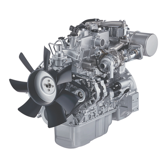
Isuzu 4LE2 Workshop Manual (872 pages)
Diesel Engine
Brand:
Isuzu
| Category:
Engine
| Size: 87 MB
Table of Contents
Description General Information
10
Table of Contents
10
Contents Included in Service Information
11
Plastic Gauge
13
Recommended Liquid Gasket
15
Thread Locking Adhesive Agent
17
Term
18
Abbreviations
19
Standard Bolts
23
Description Engine
30
Maintenance Precautions
31
Primary Specifications
34
Function, Structure, Operation
37
Introduction to the Trouble Diagnosis
77
Description Engine
88
Engine Compression Pressure Inspection
89
Fuel System Check
91
Air Intake System Check
92
Exhaust System Check
93
EGR Control System Check
94
Starting System Check
95
Glow Control System Check
96
OBD System Check
98
Inspection of the Diagnostic Light Warning Light Illumination Circuit System
99
Inspection of the Diagnostic Light Warning Light Blinking Circuit System
100
Inspection of the Starter Circuit System
101
Description Engine
102
Engine Start Failure
103
Engine Stalling
105
Engine Hunching, Rough Idling
107
Excessive White Smoke in the Exhaust Gas
108
Excessive Black Smoke in the Exhaust Gas
109
Abnormal Noise
110
Large Fuel Consumption
111
Large Oil Consumption
113
Insufficient Engine Output
114
Description Engine
116
Position Correlation
118
DTC P0087 (Flash Code 225) Fuel Rail/System Pressure - too Low
119
DTC P0089 (Flash Code 151) Fuel Pressure Regulator Performance
120
DTC P0091 (Flash Code 247) Fuel Pressure Regulator Control Circuit Low
121
DTC P0092 (Flash Code 247) Fuel Pressure Regulator Control Circuit High
122
DTC P0093 (Flash Code 227) Fuel System Leak Detected
123
Sensor Circuit Low
124
Sensor Circuit High
125
DTC P0112 (Flash Code 22) Intake Air Temperature Sensor Circuit Low
126
DTC P0113 (Flash Code 22) Intake Air Temperature Sensor Circuit High
127
Sensor Circuit Low
128
Sensor Circuit High
129
DTC P0182 (Flash Code 211) Fuel Temperature Sensor Circuit Low
130
DTC P0183 (Flash Code 211) Fuel Temperature Sensor Circuit High
131
DTC P0192 (Flash Code 245) Fuel Rail Pressure Sensor Circuit Low
132
DTC P0193 (Flash Code 245) Fuel Rail Pressure Sensor Circuit High
133
DTC P0201 (Flash Code 271) Injector Circuit - Cylinder 1
134
DTC P0202 (Flash Code 272) Injector Circuit - Cylinder 2
135
DTC P0203 (Flash Code 273) Injector Circuit - Cylinder 3
136
DTC P0204 (Flash Code 274) Injector Circuit - Cylinder 4
137
DTC P0217 (Flash Code 542) Engine Coolant over Temperature Condition
138
DTC P0219 (Flash Code 543) Engine Overspeed Condition
139
DTC P0237 (Flash Code 32) Turbocharger Boost Sensor Circuit Low
140
DTC P0238 (Flash Code 32) Turbocharger Boost Sensor Circuit High
141
DTC P0335 (Flash Code 15) Crankshaft Position Sensor Circuit
142
Circuit Range/Performance
143
DTC P0340 (Flash Code 14) Camshaft Position Sensor Circuit
144
DTC P0380 (Flash Code 66) Glow Plug Circuit
145
Control Circuit Range/Performance
146
DTC P0409 (Flash Code 44) Exhaust Gas Recirculation 1 Sensor Circuit
147
DTC P0521 (Flash Code 294) Engine Oil Pressure Sensor Performance
148
DTC P0522 (Flash Code 294) Oil Pressure Sensor Circuit Low Input
149
DTC P0523 (Flash Code 294) Oil Pressure Sensor Circuit High Input
150
DTC P0563 (Flash Code 35) System Voltage High
151
Memory Check Sum Error
152
DTC P0602 (Flash Code 154) Control Module Programming Error
153
Random Access Memory (RAM)
154
DTC P0606 (Flash Code 51) ECM/PCM Processor
155
Processing Performance
156
DTC P0615 (Flash Code 19) Starter Relay Circuit
157
DTC P0641 (Flash Code 55) Sensor Reference Voltage 1 Circuit
158
DTC P0651 (Flash Code 56) Sensor Reference Voltage 2 Circuit
159
Control Circuit/Open
160
DTC P0687 (Flash Code 416) ECM/PCM Power Relay Control Circuit High
161
DTC P0697 (Flash Code 57) Sensor Reference Voltage 3 Circuit
162
IC,Check Sum,Communication Line
163
DTC P1093 (Flash Code 227) Fuel Rail Pressure (FRP) too Low
164
DTC P1097 (Flash Code 213) Boost Temperature Sensor Circuit Low
165
DTC P1098 (Flash Code 213) Boost Temperature Sensor Circuit High
166
DTC P1261 (Flash Code 34) Fuel Injector Group 1 Supply Voltage Circuit
167
DTC P1262 (Flash Code 34) Fuel Injector Group 2 Supply Voltage Circuit
168
Closed Position Performance
169
DTC P1606 (Flash Code 51) SW-IC 1 Internal
170
DTC P160B (Flash Code 36) AD-IC Failure
171
Memory Performance
172
DTC P1655 (Flash Code 59) Sensor Reference Voltage 4 Circuit
173
DTC P2146 (Flash Code 158) Fuel Injector Group 1 Supply Voltage Circuit
174
DTC P2149 (Flash Code 159) Fuel Injector Group 2 Supply Voltage Circuit
175
DTC P2228 (Flash Code 71) Barometric Pressure Circuit Low
176
DTC P2229 (Flash Code 71) Barometric Pressure Circuit High
177
Circuit or Up/Down Switch Error
178
DTC U0073 (Flash Code 84) CAN-Bus Malfunction (J1939)
179
DTC Mapping Table
180
Description Engine
184
Position Correlation
186
DTC P0087 (Flash Code 225) Fuel Rail/System Pressure - too Low
187
DTC P0089 (Flash Code 151) Fuel Pressure Regulator Performance
188
DTC P0091 (Flash Code 247) Fuel Pressure Regulator Control Circuit Low
189
DTC P0092 (Flash Code 247) Fuel Pressure Regulator Control Circuit High
190
DTC P0093 (Flash Code 227) Fuel System Leak Detected
191
DTC P0112 (Flash Code 22) Intake Air Temperature Sensor Circuit Low
192
DTC P0113 (Flash Code 22) Intake Air Temperature Sensor Circuit High
193
Sensor Circuit Low
194
Sensor Circuit High
195
DTC P0182 (Flash Code 211) Fuel Temperature Sensor Circuit Low
196
DTC P0183 (Flash Code 211) Fuel Temperature Sensor Circuit High
197
DTC P0192 (Flash Code 245) Fuel Rail Pressure Sensor Circuit Low
198
DTC P0193 (Flash Code 245) Fuel Rail Pressure Sensor Circuit High
199
DTC P0201 (Flash Code 271) Injector Circuit - Cylinder
200
DTC P0202 (Flash Code 272) Injector Circuit - Cylinder
201
DTC P0203 (Flash Code 273) Injector Circuit - Cylinder
202
DTC P0204 (Flash Code 274) Injector Circuit - Cylinder
203
DTC P0217 (Flash Code 542) Engine Coolant over Temperature Condition
204
DTC P0219 (Flash Code 543) Engine Overspeed Condition
205
DTC P0237 (Flash Code 32) Turbocharger Boost Sensor Circuit Low
206
DTC P0238 (Flash Code 32) Turbocharger Boost Sensor Circuit High
207
DTC P0335 (Flash Code 15) Crankshaft Position Sensor Circuit
208
Circuit Range/Performance
209
DTC P0340 (Flash Code 14) Camshaft Position Sensor Circuit
210
DTC P0380 (Flash Code 66) Glow Plug Circuit
211
Control Circuit Range/Performance
212
DTC P0409 (Flash Code 44) Exhaust Gas Recirculation 1 Sensor Circuit
213
Sensor Circuit High
214
Sensor Circuit Low
215
DTC P0521 (Flash Code 294) Engine Oil Pressure Sensor Performance
216
DTC P0522 (Flash Code 294) Oil Pressure Sensor Circuit Low Input
217
DTC P0523 (Flash Code 294) Oil Pressure Sensor Circuit High Input
218
DTC P0563 (Flash Code 35) System Voltage High
219
Memory Check Sum Error
220
DTC P0602 (Flash Code 154) Control Module Programming Error
221
Random Access Memory (RAM)
222
DTC P0606 (Flash Code 51) ECM/PCM Processor
223
Processing Performance
224
DTC P0615 (Flash Code 19) Starter Relay Circuit
225
DTC P0641 (Flash Code 55) Sensor Reference Voltage 1 Circuit
226
DTC P0651 (Flash Code 56) Sensor Reference Voltage 2 Circuit
227
Control Circuit/Open
228
DTC P0687 (Flash Code 416) ECM/PCM Power Relay Control Circuit High
229
DTC P0697 (Flash Code 57) Sensor Reference Voltage 3 Circuit
230
IC,Check Sum,Communication Line
231
DTC P1093 (Flash Code 227) Fuel Rail Pressure (FRP) too Low
232
DTC P1112 (Flash Code 295) Boost Temperature Sensor Circuit Low Input
233
DTC P1113 (Flash Code 295) Boost Temperature Sensor Circuit High Input
234
DTC P1261 (Flash Code 34) Fuel Injector Group 1 Supply Voltage Circuit
235
DTC P1262 (Flash Code 34) Fuel Injector Group 2 Supply Voltage Circuit
236
DTC P1293 (Flash Code 221) Fuel Filter Pressure Sensor Circuit Low
237
DTC P1294 (Flash Code 221) Fuel Filter Pressure Sensor Circuit High
238
Closed Position Performance
239
DTC P160B (Flash Code 36) AD-IC Failure
241
Memory Performance
242
DTC P1655 (Flash Code 59) Sensor Reference Voltage 4 Circuit
243
DTC P20DE (Flash Code 221) Fuel Filter Pressure too Low
244
E-61
244
DTC P2146 (Flash Code 158) Fuel Injector Group 1 Supply Voltage Circuit
245
DTC P2149 (Flash Code 159) Fuel Injector Group 2 Supply Voltage Circuit
246
DTC P2228 (Flash Code 71) Barometric Pressure Circuit Low
247
DTC P2229 (Flash Code 71) Barometric Pressure Circuit High
248
DTC P2540 (Flash Code 221) Fuel Filter Pressure too Low
249
DTC U0073 (Flash Code 84) CAN-Bus Malfunction (J1939)
250
Transmission Control Module
251
DTC Mapping Table
252
Engine Control
256
Position Correlation
258
DTC P0087 (Flash Code 225) Fuel Rail/System Pressure - too Low
259
DTC P0089 (Flash Code 151) Fuel Pressure Regulator Performance
261
Control Circuit Low
263
Control Circuit High
264
DTC P0093 (Flash Code 227) Fuel System Leak Detected
265
Sensor Circuit Low
268
Sensor Circuit High
269
DTC P0112 (Flash Code 22) Intake Air Temperature Sensor Circuit Low
270
Circuit High
271
Sensor Circuit Low
272
DTC P0182 (Flash Code 211) Fuel Temperature Sensor Circuit Low
274
DTC P0183 (Flash Code 211) Fuel Temperature Sensor Circuit High
275
DTC P0192 (Flash Code 245) Fuel Rail Pressure Sensor Circuit Low
276
DTC P0193 (Flash Code 245) Fuel Rail Pressure Sensor Circuit High
277
DTC P0201 (Flash Code 271) Injector Circuit - Cylinder
278
DTC P0202 (Flash Code 272) Injector Circuit - Cylinder
279
DTC P0203 (Flash Code 273) Injector Circuit - Cylinder
280
DTC P0204 (Flash Code 274) Injector Circuit - Cylinder
281
Temperature Condition
282
DTC P0219 (Flash Code 543) Engine Overspeed Condition
283
Circuit High
284
DTC P0237 (Flash Code 32) Turbocharger Boost Sensor Circuit Low
284
DTC P0335 (Flash Code 15) Crankshaft Position Sensor Circuit
286
Circuit Range/Performance
288
DTC P0340 (Flash Code 14) Camshaft Position Sensor Circuit
289
Control Circuit Range/Performance
292
Sensor Circuit
292
DTC P0521 (Flash Code 294) Engine Oil Pressure Sensor Performance
295
DTC P0522 (Flash Code 294) Oil Pressure Sensor Circuit Low Input
296
High Input
297
DTC P0563 (Flash Code 35) System Voltage High
298
Memory Check Sum Error
299
DTC P0602 (Flash Code 154) Control Module Programming Error
300
Random Access Memory (RAM)
301
DTC P0606 (Flash Code 51) ECM/PCM Processor
302
Processing Performance
303
DTC P0615 (Flash Code 19) Starter Relay Circuit
304
DTC P0641 (Flash Code 55) Sensor Reference Voltage 1 Circuit
305
DTC P0651 (Flash Code 56) Sensor Reference Voltage 2 Circuit
307
Control Circuit/Open
309
DTC P0687 (Flash Code 416) ECM/PCM Power Relay Control Circuit High
310
DTC P0697 (Flash Code 57) Sensor Reference Voltage 3 Circuit
311
IC,Check Sum,Communication Line
312
DTC P1093 (Flash Code 227) Fuel Rail Pressure (FRP) too Low
313
DTC P1097 (Flash Code 213) Boost Temperature Sensor Circuit Low
315
DTC P1098 (Flash Code 213) Boost Temperature Sensor Circuit High
316
Voltage Circuit
317
DTC P1262 (Flash Code 34) Fuel Injector Group 2 Supply
318
Closed Position Performance
319
DTC P160B (Flash Code 36) AD-IC Failure
321
DTC P1655 (Flash Code 59) Sensor Reference Voltage 4 Circuit
323
DTC P2228 (Flash Code 71) Barometric Pressure Circuit Low
326
DTC P2229 (Flash Code 71) Barometric Pressure Circuit High
327
Circuit or Up/Down Switch Error
328
DTC U0073 (Flash Code 84) CAN-Bus Malfunction (J1939)
329
Engine Control
330
DTC P0087 (Flash Code 225) Fuel Rail/System Pressure - too Low
333
DTC P0089 (Flash Code 151) Fuel Pressure Regulator Performance
336
Control Circuit Low
338
Control Circuit High
339
DTC P0093 (Flash Code 227) Fuel System Leak Detected
340
DTC P0112 (Flash Code 22) Intake Air Temperature Sensor Circuit Low
343
Sensor Circuit Low
345
DTC P0182 (Flash Code 211) Fuel Temperature Sensor Circuit Low
347
DTC P0183 (Flash Code 211) Fuel Temperature Sensor Circuit High
348
DTC P0192 (Flash Code 245) Fuel Rail Pressure Sensor Circuit Low
349
DTC P0193 (Flash Code 245) Fuel Rail Pressure Sensor Circuit High
350
DTC P0201 (Flash Code 271) Injector Circuit - Cylinder
351
DTC P0202 (Flash Code 272) Injector Circuit - Cylinder
352
DTC P0203 (Flash Code 273) Injector Circuit - Cylinder
353
DTC P0204 (Flash Code 274) Injector Circuit - Cylinder
354
DTC P0219 (Flash Code 543) Engine Overspeed Condition
356
DTC P0237 (Flash Code 32) Turbocharger Boost Sensor Circuit Low
357
DTC P0335 (Flash Code 15) Crankshaft Position Sensor Circuit
359
Circuit Range/Performance
361
DTC P0340 (Flash Code 14) Camshaft Position Sensor Circuit
362
Control Circuit Range/Performance
365
Sensor Circuit
365
Sensor Circuit High
368
Sensor Circuit Low
369
DTC P0521 (Flash Code 294) Engine Oil Pressure Sensor Performance
370
DTC P0522 (Flash Code 294) Oil Pressure Sensor Circuit Low Input
371
DTC P0563 (Flash Code 35) System Voltage High
373
Memory Check Sum Error
374
DTC P0602 (Flash Code 154) Control Module Programming Error
375
Random Access Memory (RAM)
376
DTC P0606 (Flash Code 51) ECM/PCM Processor
377
DTC P0615 (Flash Code 19) Starter Relay Circuit
379
DTC P0641 (Flash Code 55) Sensor Reference Voltage 1 Circuit
380
DTC P0651 (Flash Code 56) Sensor Reference Voltage 2 Circuit
382
Control Circuit/Open
384
IC,Check Sum,Communication Line
387
DTC P1093 (Flash Code 227) Fuel Rail Pressure (FRP) too Low
388
Circuit Low Input
391
Circuit High Input
392
DTC P1261 (Flash Code 34) Fuel Injector Group 1 Supply
393
DTC P1262 (Flash Code 34) Fuel Injector Group 2 Supply
394
DTC P1293 (Flash Code 221) Fuel Filter Pressure Sensor Circuit Low
395
Closed Position Performance
397
DTC P160B (Flash Code 36) AD-IC Failure
399
DTC P1655 (Flash Code 59) Sensor Reference Voltage 4 Circuit
401
DTC P20DE (Flash Code 221) Fuel Filter Pressure too Low
402
DTC P2228 (Flash Code 71) Barometric Pressure Circuit Low
405
DTC P2229 (Flash Code 71) Barometric Pressure Circuit High
406
DTC P2540 (Flash Code 221) Fuel Filter Pressure too Low
407
DTC U0073 (Flash Code 84) CAN-Bus Malfunction (J1939)
408
Transmission Control Module
409
Engine
410
Cylinder Head Cover
411
Removal
411
Installation
413
Cylinder Head Assembly
416
Removal
416
Disassembly
423
Inspection
424
Reassembly
430
Installation
433
Idle Gear
444
Removal
444
Inspection
448
Installation
449
Cylinder Block
453
Removal
453
Inspection
467
Installation
469
Exhaust Manifold
490
Removal
490
Installation
493
Crankshaft
497
Removal
497
Disassembly
510
Inspection
511
Reassembly
513
Installation
514
Piston
533
Removal
533
Disassembly
541
Inspection
542
Reassembly
546
Installation
548
Camshaft
561
Removal
561
Inspection
570
Installation
572
Flywheel
586
Removal
586
Inspection
588
Installation
589
Crankshaft Front Oil Seal
591
Removal
591
Installation
593
Crankshaft Rear Oil Seal
596
Removal
596
Installation
599
Rocker Arm Shaft
603
Removal
603
Inspection
606
Installation
608
Valve Spring
613
Removal
613
Inspection
620
Installation
621
Valve Stem Oil Seal
633
Removal
633
Installation
641
CMP Sensor
654
Removal
654
Inspection
655
Installation
656
CKP Sensor
657
Removal
657
Inspection
658
Installation
659
Engine Speed Sensor
660
Removal
660
Inspection
661
Installation
662
Intake Chamber
663
Removal
663
Installation
666
Supplementary Information
669
Engine
692
Fuel Supply Pump
693
Removal
693
Installation
696
Common Rail Assembly
700
Removal
700
Installation
701
Injector
702
Removal
702
Installation
705
Suction Control Valve
708
Removal
708
Installation
709
Fuel Filter
710
Removal
710
Installation
711
Fuel Temperature Sensor
712
Removal
712
Installation
715
Pressure Limiter
719
Removal
719
Installation
720
Fuel Pressure Sensor
721
Removal
721
Installation
722
Fuel Filter Pressure Sensor
723
Removal
723
Installation
724
Supplementary Information
725
Engine
732
Water Pump Assembly
733
Removal
733
Inspection
735
Installation
736
Thermostat
739
Removal
739
Inspection
740
Installation
741
Cooling Fan Belt
742
Inspection
742
Radiator
743
Inspection
743
Engine Coolant Temperature Sensor
744
Removal
744
Inspection
745
Installation
746
Coolant
747
Inspection
747
Supplementary Information
749
Engine
754
Oil Pan
755
Removal
755
Installation
756
Oil Pump Assembly
757
Removal
757
Installation
762
Oil Cooler Assembly
768
Removal
768
Installation
769
Oil Pressure Sensor
771
Removal
771
Installation
772
Engine Oil
773
Inspection
773
Oil Filter Element
774
Removal
774
Installation
775
Supplementary Information
776
Engine
782
Turbocharger Assembly
783
Removal
783
Installation
785
Intercooler
788
Inspection
789
Air Cleaner Element
789
IMT Sensor
790
Removal
790
Installation
792
Pressure Sensor/Boost Temperature Sensor
794
Removal
794
Inspection
795
Installation
796
Supplementary Information
797
Integrated Oxidation Catalyst Silencer
801
Removal
801
Installation
802
Supplementary Information
804
Exhaust (4LE2)
805
EGR Valve
807
Removal
807
Inspection
809
Installation
810
Supplementary Information
812
Engine
814
Glow Plug
815
Removal
815
Inspection
818
Installation
819
Install the Turbocharger Heat Protector to the
821
Securely Tighten the Support Bracket to the Silencer Bracket. Tightening Torque: 24 N・M { 2.4 Kgf・M / 18 Lb・Ft
821
Tightening Torque: 10 N・M { 1.0 Kgf・M / 89 Lb・In } M6
821
Tightening Torque: 27 N・M { 2.8 Kgf・M / 20 Lb・Ft } M8
821
Turbocharger Heat Protector Installation
821
Generator
823
Removal
823
Inspection
824
Installation
828
Ecm
830
Removal
830
Installation
831
Starter Motor
832
Removal
832
Inspection
833
Installation
835
Supplementary Information
836
Advertisement
Isuzu 4LE2 Owner's Manual (107 pages)
TIER 4/STAGE 3B
Brand:
Isuzu
| Category:
Engine
| Size: 2 MB
Table of Contents
Notes on Reading this Manual
2
Symbols Used in this Manual
3
How to Use this Manual
6
Chapter Index Tab
6
Chapter/Section Titles
6
Use Chapter/Section Titles as Keys
7
Table of Contents
9
Chapter Description
9
Pictorial Index
10
Exterior
10
Information
13
Engine Number/Emission Label/Special Vehicle Labels
15
Engine Number/ID (Identification) Labels
15
Location of Engine Number
15
Emission Labels
16
Special Vehicle Label
16
Exhaust Emission Regulation Related Parts
16
Important Information
17
Before Operating the Engine
18
Fuel, Lubricant and Coolant
18
Using Fuel Other than Extra-Low-Sulfur Diesel Fuel (with Sulfur Content of
18
Diesel Fuel/Applicable Standard (Sulphur Content below 15 Ppm)
19
When Selecting Fuels (for United States and Canada Only)
19
Refueling Using Fuels that Contain Biodiesel Fuel (Fatty Acid Methyl Esters (FAME)) (for Europe Only)
20
Refueling Using Fuels that Contain Biodiesel Fuel (for United States and Canada Only)
20
Handling the Fuel
21
Lubricant (Engine Oil)
22
Coolant
22
Operating the Engine
23
Handling in Initial Use Phase
23
If the Engine Has Not Been Used for a Long Period
24
Be Careful with Exhaust Emissions
25
When Leaving the Engine Running
25
Be Careful with the too Cold Engine
26
Recommendations for Warming up the Engine
26
Do Not Turn off the Engine While the Machine Is Running
26
Staying Safe
27
When the Engine Coolant Is Hot
27
When the Silencer and Exhaust Pipe Are Hot
27
When the Warning Light Comes on
27
Do Not Climb Onto the Engine
28
Make Sure the Engine Is Inspected at Regular Intervals
28
Preventing Engine Failure
28
If the Battery Goes Flat
28
When to Visit an Isuzu Distributor
29
Do Not Modify the Engine
29
Handling Electric Accessories
29
Inspection and Maintenance
30
Handling of Engine
31
Starting the Engine
32
Inspection Method after the Engine Started
34
Engine Oil Pressure
34
Engine Warning Light/Engine Failure Code
35
Generator Warning Light
35
Abnormal Noise of Engine and Color of Exhaust Smoke
36
Abnormal Noise of Engine
36
Color of Exhaust Smoke
36
Coolant Temperature
37
Hour Meter (Cumulative Operating Hour Counter)
37
Stopping the Engine
38
Handling the Engine with Turbocharger
39
Handling in Cold Season
41
Cautions for Use in Cold Regions and Seasons
42
Handling the Coolant
42
Replacing the Engine Oil
43
Fuel
43
Fuel Requirements (for United States and Canada Only)
43
Battery
44
Storage in Cold Regions
45
Precautions for Inspections and Adjustments
48
Recommended Lubricants and Diesel Fuels
49
Discarded Parts, Oils and Other Liquids
49
Isuzu Genuine Oils and Grease
49
Daily (Pre-Operating) Inspection
50
Inspecting Components that Showed Abnormalities During Previous Operation
51
Inspecting Engine Startability and Abnormal Noise
51
Inspecting Condition of the Engine at Low Speeds and During Acceleration
51
Selecting Engine Oil
52
Engine Oil Viscosity
52
Inspecting the Engine Oil
53
Oil Identification Logo (for United States and Canada Only)
53
Adding the Engine Oil
54
To Replace the Engine Oil
55
One-Touch Type
55
Drain Plug Type
56
Engine Oil Filter
57
Generator Drive Belt
59
Adjusting the Generator Drive Belt
60
Inspecting the Generator Drive Belt
60
Measurement of Deflection Amount and Vibration Frequency
60
Replacing the Generator Drive Belt
61
Coolant Info
62
Handling the Long-Life Coolant
62
Inspecting the Coolant
64
Replacing the Coolant
64
Draining the Cooling System
65
Cleaning the Coolant Passages
65
Filling the Cooling System
66
Cleaning the Radiator Exterior
67
Fuel Filter
67
Draining Water from the Fuel Filter
68
Bleeding the Fuel System
69
Changing the Fuel Filter
70
Inspecting the Supply Pump Strainer
71
Electromagnetic Fuel Pump
72
Replacing or Cleaning the Filter
72
Handling the Fuel Piping
73
Air Cleaner
74
Valve Clearance/Others
74
Adjusting the Valve Clearance
75
Measuring the Engine Compression Pressure
77
Starter, Generator
77
Inspecting the Radiator Cap
77
Battery Handling Precautions
78
When Performing Inspection and Maintenance
79
When Removing Battery
79
Inspecting the Battery Fluid Level and Adding the Battery Fluid
80
When Charging Battery
80
When Connecting Battery Cable
80
When Taking out Power Supply Directly from Battery
80
Conversion of Specific Gravity
81
Inspecting the Battery Terminals
81
Inspecting the Specific Gravity of Battery Fluid
81
Periodic Inspection and Maintenance List
82
Lubrication System
82
Fuel System
83
Cooling System
84
Inspection and Maintenance
84
Intake/Exhaust System
85
Electrical System
86
Engine/Others
87
In Case of Emergency
89
Cause of Failure and Corrective Action
90
When the Battery Goes Flat
93
When the Fuel Runs out
95
Main Data
97
Main Data and Specifications
98
Engine Data
98
Index
99
Isuzu 4LE2 Workshop Manual (121 pages)
INDUSTRIAL DIESEL ENGINE
Brand:
Isuzu
| Category:
Engine
| Size: 10 MB
Table of Contents
Table of Contents
4
General Repair Instructions
5
Notes on the Format of this Manual
5
Appearance
8
Main Data and Specifications
9
Tightening Torque Specifications
10
Angular Nut and Bolt Tightening Method
12
Tightening Torque on Major Components
14
Gasket Location
20
Maintenance
23
Recommended Lubricating Oil
28
Length
112
Area
114
Volume
114
Mass
116
Pressure
117
Torque
118
Temperature
119
Advertisement
Isuzu 4LE2 Instruction Manual (48 pages)
Brand:
Isuzu
| Category:
Engine
| Size: 5 MB
Table of Contents
Table of Contents
5
Engine External Views
7
General Information
9
Epa Certified Engine Data and Specifications
9
Ec Emission Control Label
13
Engine /Dent/Fica T/On
14
Isuzu Engine after Service
15
Fuel
16
Lubricant
22
Coolant
23
Engine Operation
24
Check before Operation
26
Engine Starting
32
Check and Operation after the Engine Start-Up
36
Care in the Engine Operation
39
Engine Stopping
45
Operation and Care for New Engine
46
Engine Care for Over-Cooling
46
Advertisement
Related Products
Isuzu 4LE1 PW-03
Isuzu 4LE1 PW-15
Isuzu 4LE2-PW10
Isuzu 4LE
Isuzu 4LE1
Isuzu 4LB1-PA04
Isuzu 4LB1-PW01
Isuzu 4LC1 PW-01
Isuzu 4LC
Isuzu 4LB1
Isuzu Categories
Engine
Utility Vehicle
Automobile
Trucks
Control Systems
More Isuzu Manuals
Login
Sign In
OR
Sign in with Facebook
Sign in with Google
Upload manual
Upload from disk
Upload from URL