Sign In
Upload
Manuals
Brands
ABB Manuals
Measuring Instruments
CoriolisMaster FCD400
ABB CoriolisMaster FCD400 Manuals
Manuals and User Guides for ABB CoriolisMaster FCD400. We have
1
ABB CoriolisMaster FCD400 manual available for free PDF download: Operating Instruction
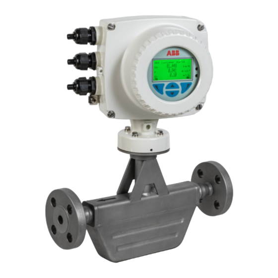
ABB CoriolisMaster FCD400 Operating Instruction (172 pages)
Coriolis mass flowmeter
Brand:
ABB
| Category:
Measuring Instruments
| Size: 13 MB
Table of Contents
Table of Contents
2
Safety
5
General Information and Instructions
5
Warnings
5
Intended Use
6
Improper Use
6
Cyber Security Disclaimer
6
Software Downloads
6
Warranty Provisions
7
Manufacturer's Address
7
Service Address
7
Use in Potentially Explosive Atmospheres
8
Device Overview
8
ATEX, Iecex and UKEX
8
Cfmus
9
Ex Marking
10
Description of Model Numbers
10
ATEX, Iecex and UKEX
13
Temperature Data
15
Temperature Resistance for the Connecting Cable
15
Environmental and Process Conditions for Model Fcx4Xx
15
Measuring Medium Temperature for Sensors in Integral Mount Design with Dual-Compartment Housing
16
Measuring Medium Temperature for Sensors in Integral Mount Design with Single-Compartment Housing
17
Measuring Medium Temperature for Sensors in Remote Mount Design
18
Electrical Data
19
Overview
19
Zone 2, 21 and Division 2 - Model: Fcx4Xx-A2
20
Zone 1 ,21 and Division 1 - Model: Fcx4Xx-A1
22
Special Connection Conditions
24
Installation Instructions
25
ATEX, Iecex and UKEX
25
Cfmus
25
Use in Areas Exposed to Combustible Dust
25
Sensor Insulation
25
Opening and Closing the Housing
25
Cable Entries in Accordance with Atex/Iecex and UKEX
26
Cable Entries in Accordance with Cfmus
26
Specific Conditions of Use
27
Electrical Connections
27
Process Sealing
28
Operating Instructions
28
Protection against Electrostatic Discharges
28
Repair
28
Design and Function
29
General
29
Measuring Principle
29
Device Designs
30
Product Identification
32
Name Plate
32
Transport and Storage
33
Inspection
33
Transporting the Device
33
Storing the Device
34
Ambient Conditions
34
Returning Devices
34
Installation
34
General Installation Conditions
34
Installation Location and Assembly
34
Installation Position / Installation Conditions
35
Liquid Measuring Media
35
Gaseous Measuring Media
36
Turn-Off Devices for the Zero Point Adjustment
37
Sensor Insulation
37
Process Conditions
38
Temperature Limits °C (°F)
38
Temperature Data
38
Pressure Ratings
38
Material Load for Process Connections
38
Material Load Curves for Flange Devices
38
Installing the Sensor
39
Installing the Transmitter in the Remote Mount Design
39
Opening and Closing the Housing
41
Dual- Compartment Housing
41
Single-Compartment Housing
42
Adjusting the Transmitter Position
42
Transmitter Housing
42
Rotate LCD Indicator - Dual-Compartment Housing
43
Rotate LCD Indicator - Single-Compartment Housing
43
Installing the Plug-In Cards
44
Optional Plug-In Cards
44
Dual-Compartment Housing
46
Single-Compartment Housing
47
Ethernet Card
48
Electrical Connections
49
Safety Instructions
49
Power Supply
49
Installing the Connection Cables
50
General Information on Cable Installation
50
Signal Cable Specification
50
Recommended Cables
50
Terminal Assignment
51
Electrical Data for Inputs and Outputs
52
Power Supply L / N, 1+ / 2
52
Requirements for Inputs and Outputs
52
Current Output 32 / Uco, 31 / 32 (Basic Device)
52
Current Output Uco / 32 as Loop Power Supply for Digital Output 41 / 42 or 51 / 52
53
Digital Output 41 / 42, 51 / 52 (Basic Device)
54
Current Output V1 / V2, V3 / V4 (Plug-In Module)
54
Passive Digital Output V1 / V2, V3 / V4 (Plug-In Card)
55
Active Digital Output V1 / V2, V3 / V4 (Plug-In Card)
55
Digital Input V1 / V2, V3 / V4 (Plug-In Module)
56
DC Loop Power Supply (Plug-In Card)
57
Modbus® / PROFIBUS DP® Interface V1 / V2 (Plug-In Card)
57
Connection Examples
57
Connection on the Device
60
Connection to Integral Mount Design
60
Connection to Remote Mount Design
62
Digital Communication
65
HART® Communication
65
Modbus® Communication
65
Cable Specification
66
PROFIBUS DP® Communication
66
Ethernet/Ip™ and PROFINET® Communication
67
Ethernet Communication
68
Wiring with Different Network Topologies
69
Connect the Retractable Plug to the Ethernet Card
70
Preparing the Ethernet Cat5E Cable
71
Ground the Ethernet Connection Cable
71
M12 Connector (Optional)
71
RJ45 Connector (Optional)
72
Ethernet Card Status Leds
74
Commissioning
76
Safety Instructions
76
Hardware Settings
76
Dual- Compartment Housing
76
Single-Compartment Housing
77
Checks Prior to Commissioning
78
Switching on the Power Supply
78
Parameterization of the Device
78
Installation of the ABB Field Information Manager (FIM)
79
Parameterization Via the Infrared Service Port Adapter
80
Parameterization Via HART
80
Basic Setup
81
Menu: Easy Setup
81
10 Operation
85
Safety Instructions
85
Menu Navigation
85
Menu Levels
86
Process Display
87
Switching to the Information Level
87
Error Messages on the LCD Display
88
Switching to the Configuration Level (Parameterization)
88
Selecting and Changing Parameters
90
Available Units
92
Available Process Variables
94
Parameter Overview
97
Parameter Descriptions
109
Menu: Easy Setup
109
Menu: Device Info
113
Menu: Device Setup
115
Menu: Display
123
Menu: Input/Output
124
Menu: Process Alarm
133
Menu: Communication
134
Menu: Diagnostics
139
Menu: Totalizer
143
Software History
145
Zero Point Balance under Operating Conditions
145
Measurement of Standard Volumes
146
Verimass Erosion Monitor
148
Setup
148
Enhanced Coriolis Control (Ecc)Function
149
Applications in Accordance with API (American Petroleum Institute)
150
Concentration Measurement Densimass
150
Calculating Standard Volumes and Standard Densities of Liquids
150
Accuracy of the Concentration Measurement
151
Entering the Concentration Matrix
151
Fillmass Batch Function
154
11 Diagnosis / Error Messages
155
Calling up the Error Description
155
General
155
Overview
156
Error Messages
158
12 Maintenance
162
Safety Instructions
162
Sensor
162
Repairs to the Flowmeter
162
Cleaning
162
13 Repair
162
Spare Parts
163
Replacing the Fuse
163
Replacing the LCD Indicator
164
Replacing the Frontend Board
165
Integral Mount Design
165
Remote Mount Design
167
Replacing the Sensor
168
Returning Devices
168
14 Dismounting and Disposal
169
Dismounting
169
Disposal
169
15 Specification
169
16 Additional Documents
169
17 Appendix
170
Return Form
170
Advertisement
Advertisement
Related Products
ABB CoriolisMaster FCM2000
ABB CoriolisMaster FCB100
ABB CoriolisMaster FCB400
ABB CoriolisMaster FCB450
ABB CoriolisMaster FCH430
ABB CoriolisMaster FCH450
ABB CoriolisMaster FCB350
ABB CoriolisMaster FCH330
ABB CoriolisMaster FCHB400
ABB CoriolisMaster FCH400 Series
ABB Categories
Industrial Equipment
Controller
Measuring Instruments
Battery Charger
DC Drives
More ABB Manuals
Login
Sign In
OR
Sign in with Facebook
Sign in with Google
Upload manual
Upload from disk
Upload from URL