Table of Contents
Advertisement
Quick Links
Advertisement
Table of Contents

Related Manuals for ABB EGW-02


Summary of Contents for ABB EGW-02
- Page 1 — EGW-02 Connectivity Edge Gateway User's manual...
- Page 3 EGW-02 Connectivity Edge Gateway User's manual Table of contents 3. Mechanical installation 4. Electrical installation 3AXD50000929719 Rev A Original instructions EFFECTIVE: 2024-01-19...
-
Page 5: Table Of Contents
Contents of this chapter ............... . EGW-02 gateway and ABB Ability™ Condition Monitoring for drives (CMD) .. - Page 6 6 Table of contents 6 User instructions Contents of this chapter ............... . Device management and firmware updates .
-
Page 7: Introduction To The Manual
Introduction to the manual Contents of this chapter This chapter introduces this manual. Applicability This manual is applicable to the EGW-02 Connectivity Edge Gateway. It is later referred to as EGW-02 gateway or gateway. Safety WARNING! Obey the safety instructions of the drive. If you ignore them, injury or death, or damage to the equipment can occur. -
Page 8: Terms And Abbreviations
ABB and its affiliates are not liable for damages and/or losses related to such security breaches, any unauthorized access, interference, intrusion, leakage and/or theft of... -
Page 9: Overview
(CMD) The EGW-02 gateway supports ABB Ability™ Condition Monitoring for drives (later CMD service) which is part of the ABB Ability™ Digital Powertrain. CMD is a cloud service for the drive data storing, monitoring and analysis. CMD service is for monitoring only. -
Page 10: System Overview
EGW-02 gateway provides a cloud connectivity for ABB drives. For a cabinet-installed drive, ABB factory installs the gateway to the drive cabinet line-up, and connects the gateway to the drive control board(s) and power supply. On the drive installation site, the customer connects the gateway to the public Internet and ABB cloud service either through a mobile antenna and cellular modem, or through a wired Ethernet. -
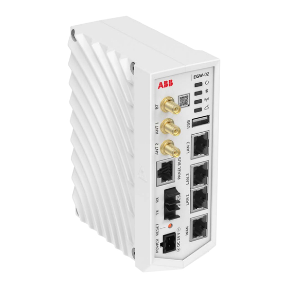
Page 11: Connectors And Led Indicators
Overview 11 Connectors and LED indicators Explanation Symbol LTE MIMO antenna connectors for mobile Internet connection. ANT 1, ANT 2 1a) RX diversity antenna, 1b) main antenna. Bluetooth 5 antenna connector. There is no Bluetooth support at the moment. RS-485 connector for panel bus PANEL BUS Fiber optic connectors for alternative drive network connection DDCS, TX, RX... -
Page 12: Type Designation Label
Made in Estonia Contains FCC ID: XMR201903EG25G Origin Estonia Contains IC: 10224A-201903EG25G This is the type designation label template. Each EGW-02 gateway has the label with the valid data values. In addition, there is a separate label showing the valid certificates. -
Page 13: Mechanical Installation
Mechanical installation Contents of this chapter This chapter contains instructions on unpacking and mechanical installation of the EGW-02 gateway, and guidelines for installing the antennas. Tools and accessories You can attach the gateway on an installation rail without tools. Unpacking Open the package and make sure that it contains: •... -
Page 14: Installing The Gateway To A Din Rail
14 Mechanical installation Installing the gateway to a DIN rail If the installation rail is not installed, install it. Attach the gateway onto the rail. Removing the gateway from the installation rail Lift the module against the spring until the upper locking claw releases behind the rail. - Page 15 Mechanical installation 15 1. High signal strength. Point this side of the antenna towards the nearest cellular tower. 2. Low signal strength.
-
Page 17: Electrical Installation
Electrical installation 17 Electrical installation Contents of this chapter This chapter introduces how to connect the EGW-02 gateway to an ABB drive. Safety WARNING! Obey the safety instructions of the drive. If you ignore them, injury or death, or damage to the equipment can occur. If you are not a qualified electrical professional, do not do installation, commissioning or maintenance work. -
Page 18: Connections
18 Electrical installation Connections Power supply connection ■ Use power supply that complies with Electrical specific- ations (page 38). 1. Connect the power supply cable to the plug connector in the gateway delivery. Pay attention to the correct polarity (+,-). 2. -
Page 19: Drive Communication Link Connection - Ddcs Fibre Optic Link
Electrical installation 19 Drive communication link connection - DDCS fibre optic link ■ Use cable that complies with Cable specification (page 39). Connect the fibre optic cables to DDCS connector of the gateway. The maximum number of devices per fiber optic link is 10. The diagram below shows an example connection of drives with RDCU control units and RDCO adapter modules. -
Page 21: Configuration And Start-Up
Registering the gateway Contact ABB to register the gateway: https://new.abb.com/contact/form#. Configuring the gateway When a new gateway is taken into use, the customer needs to log in to the EGW-02 user interface to configure the gateway. Refer to Local user interface (page 23). -
Page 23: User Instructions
• update the firmware. Local user interface When a new gateway is taken into use, the customer needs to log in to the EGW-02 user interface to configure the gateway. Note: The gateway must be registered to access the user interface. Refer to... -
Page 24: Logging In
Request an access token from ABB. Access to local UI requires an access token through DMS. Only authorized personnel can create the token. Go to EGW-02 user interface and paste the token to Access Token field. Select Log In. You are redirected to the UI home page. -
Page 25: Configuration
User instructions 25 Navigation bar: • home • configuration • diagnostics • drives • logout. Gateway details: • gateway serial number • host name • firmware version • architecture • kernel • connectivity type. Active network settings • Eth0 IP address •... - Page 26 26 User instructions Select Automatic DHCP, DHCP server or Manual: • automatic DHCP: the DHCP server has already been set up in the customer's environment and the gateway will get the IP address from the server. • DHCP server: the gateway should run as a DHCP server (IP address should come from the gateway).
- Page 27 User instructions 27 Select Automatic DHCP or Manual: • automatic DHCP: the DHCP server has already been set up in the customer's environment and the gateway will get the IP address from the server. • manual: you need to set the IP address, subnet mask, default gateway and preferred DNS server.
- Page 28 28 User instructions Select the proxy: HTTP or HTTPS. Set address. Set port number. Select if the proxy is authenticated or not: • authenticated: insert username and password. • not authenticated: no username or password needed. Select Submit. To clear the proxy settings, select Unset HTTPS proxy. Select the proxy you want to unset.
-
Page 29: Ssh Keys
Open a tool for generating SSH keys on your PC. Use the tool to generate a new SSH key. Copy the generated key to Public key field in the EGW-02 UI. Add name to the Name field. Select Add key. The key is added to the SSH keys page in the UI. -
Page 30: Device Interface
30 User instructions Device interface Two device interfaces are supported: DDCS through optical fiber connection and Ethernet. DDCS To adjust DDCS settings: Go to Device Interface > DDCS. Select Edit. A new window opens. Set optical power. Set communication speed. Set network topology. -
Page 31: Diagnostics
User instructions 31 Ethernet To adjust Ethernet settings: Go to Device Interface > Eternet. Select the way to filter the drives you want to discover: • range: set the start IP address and end IP address. Only drives that are within the range will be discovered •... -
Page 32: Drive Details
32 User instructions Drive details ■ On Drive details page, you see a list of drives that are connected to the gateway. The data is view only, no settings can be adjusted on this page. If you want to pair the serial numbers, send a screenshot of this view to the person who does the DMS configuration. -
Page 33: Troubleshooting
Troubleshooting 33 Troubleshooting Contents of this chapter This chapter contains description of the LEDs and related diagnostics and troubleshooting instructions. Ethernet connector LEDs LEDs Explanation Status Link data transfer speed Off: 10 Mbps Green: 100 Mbps Link status Off: Link not established Yellow flashing: Activity in the link Yellow: Link established... - Page 34 Make sure that the Ethernet cable is connected (or the mobile antenna is connected and the connection is tightened). Gateway error. Reset the gateway. Refer to section System recovery (page 35). Gateway is not registered. Contact ABB. No ABB cloud service is available. Contact ABB.
-
Page 35: System Recovery
Troubleshooting 35 System recovery To do a reset, push the reset button with a blunt object. Do not use a sharp object. • To do a soft reset, push the reset button for 5 seconds. • To do a hard reset, push the reset button for 15 seconds. -
Page 37: Technical Data
Technical data 37 Technical data Contents of this chapter This chapter contains technical data of the EGW-02 gateway. Dimension drawings 50 [1.97] 122.6 [4.83] 105.3 [4.15] 109.1 [4.30] The dimensions are in millimeters and [inches]. The weight of the gateway is 800 g... -
Page 38: Package Dimensions
38 Technical data Package dimensions Width × depth × height: 220 × 56 × 149 mm (8.7 × 2.2 × 5.9 in). Environmental specifications Do not use the WiFi or Bluetooth of this gateway within a 20 km radius of the center of Ny-Ålesund at Svalbard, Norway. -
Page 39: Cable Specification
LTE cellular modem Cloud connection Outbound connection to cloud Bluetooth 5 Connect to sensors Local short-range connection for sensors, e.g. ABB Abilty™ Smart Sensor Supported cellular bands Region Technology Supported bands B2, B4, B5, B7, B8, B12, B13, B20, B25,... -
Page 40: Bluetooth Antenna Specification
40 Technical data Bluetooth antenna specification Frequency range 2400…2483.5 MHz Nominal impedance 50 ohm Antenna cable 50 ohm, low-loss coaxial cable 0.5…20.0 m (1…65 ft) with SMA male connector Antenna type Manufacturer: 2J Antennas Model: 2J6702B Band: 2.4 GHz Installation kit ordering code: 3AXD50001082802 Interfaces Function Specifications... -
Page 41: Compliance And Directives
■ Hereby, ABB declares that the radio equipment type EGW-02 is in compliance with Directive 2014/53/EU. The full text of the EU declaration of conformity is available in Internet by ABB. Regulatory information ■ Federal Communications Commission Notice (FCC – United States) FCC ID: 2AFNG-EGW02 This device complies with part 15 of the FCC Rules. -
Page 42: Innovation, Science And Economic Development Notice (Ised - Canada)
42 Technical data Innovation, Science and Economic Development Notice (ISED – Canada) IC: 20555-EGW02 This device contains licence-exempt transmitter(s)/receiver(s) that comply with Innovation, Science and Economic Development Canada’s licence-exempt RSS(s) and complies with part 15 of the FCC Rules. Operation is subject to the following two conditions: This device may not cause harmful interference. -
Page 43: Radio Frequency, Antenna Gain And Transmitted Output Power Information
Technical data 43 Radio frequency, antenna gain and transmitted output power ■ information Technology Band Frequency range Maximum radiated aver- age output power GSM/2G 880…915 1800 1710…1785 28.4 WCDMA/3G 1920…1980 30.6 1710…1785 30.6 880…915 28.2 LTE/4G 1920…1980 30.6 1710…1785 30.6 824…849 28.2 2500…2570... - Page 44 44 Technical data Technology Band Frequency range Maximum conduc- Maximum an- ted average out- tenna gain put power LTE/4G 1850…1910 1710…1785 1710…1785 2500…2570 699…716 777…787 1850…1915 814…849 2570…2620 2496…2690 1) 2J Antennas: 2J6983Ba Technology Band Frequency range Maximum radi- Maximum an- ated average out- tenna gain put power...
-
Page 45: Network Connection Example
Network connection example 45 Network connection example... - Page 46 46 Network connection example...
-
Page 47: Further Information
Product and service inquiries Address any inquiries about the product to your local ABB representative, quoting the type designation and serial number of the unit in question. A listing of ABB sales, support and service contacts can be found by navigating to www.abb.com/contact-centers. - Page 48 3AXD50000929719A © Copyright 2024 ABB. All rights reserved. Specifications subject to change without notice.
Need help?
Do you have a question about the EGW-02 and is the answer not in the manual?
Questions and answers