Table of Contents
Advertisement
Installation, Operation, and Maintenance
Split System Air Conditioners
Odyssey™ with Symbio™
Controls
Air Handler — 5 to 25 Tons
(60 Hz)
TWE060K*A/B
TWE072K*B
TWE090K*A/B
TWE120K*A/B
TWE150K*B
TWE180K*B
TWE240K*B
TWE300K*B
Only qualified personnel should install and service the equipment. The installation, starting up, and servicing of heating, ventilating, and air-conditioning equipment
can be hazardous and requires specific knowledge and training. Improperly installed, adjusted or altered equipment by an unqualified person could result in death or
serious injury. When working on the equipment, observe all precautions in the literature and on the tags, stickers, and labels that are attached to the equipment.
August 2024
SAFETY WARNING
SS-SVX016A-EN
Advertisement
Table of Contents

Related Manuals for Trane Odyssey TWE060K A Series


Summary of Contents for Trane Odyssey TWE060K A Series
- Page 1 Installation, Operation, and Maintenance Split System Air Conditioners Odyssey™ with Symbio™ Controls Air Handler — 5 to 25 Tons (60 Hz) TWE060K*A/B TWE072K*B TWE090K*A/B TWE120K*A/B TWE150K*B TWE180K*B TWE240K*B TWE300K*B SAFETY WARNING Only qualified personnel should install and service the equipment. The installation, starting up, and servicing of heating, ventilating, and air-conditioning equipment can be hazardous and requires specific knowledge and training.
- Page 2 (HCFCs). Not all refrigerants containing these compounds bump cap, fall protection, electrical PPE and arc have the same potential impact to the environment. Trane flash clothing). ALWAYS refer to appropriate advocates the responsible handling of all refrigerants.
- Page 3 This document and the information in it are the property of regulations. Trane, and may not be used or reproduced in whole or in part without written permission. Trane reserves the right to revise this publication at any time, and to make changes to...
-
Page 4: Table Of Contents
Table of Contents Model Number Description ....5 Auxiliary Drain Pan ....29 Air Handler . -
Page 5: Model Number Description
Model Number Description Air Handler Digit 1, 2, 3 — Unit Function Digit 8 — Voltage Digit 14 — Efficiency Generation TWE = Air Handler 1 = 208-230 Vac - 1 PH (60 Hz) B = Generation B 3 = 208-230 Vac - 3 PH (60 Hz) 4 = 460 Vac - 3 PH (60 Hz) Digit 4, 5, 6—... -
Page 6: General Information
They are return or escalation to the VFD manufacturer shipped ready for horizontal installation. requires a Trane Technical Support ticket number FIRST. Removal of the VFD prior to All units have one drain pan that can be installed in any one this step will void the unit’s warranties. -
Page 7: A2L Information
• To be repaired only by trained service At all times, Trane’s maintenance and service guidelines personnel. shall be followed. If in doubt, contact Trane technical support for assistance. • Do not puncture refrigerant tubing. All maintenance staff and others working in the local area •... -
Page 8: Leak Detection
Verify continuity of earth bonding. The recovery equipment shall be in good working order • Replace electrical components with Trane replacement with instructions available. Equipment shall be suitable for parts, or those meeting the same ratings and qualified the recovery of the flammable refrigerant. For specific for flame arrest protection, UL LZGH2 category. -
Page 9: Decommissioning
A2L Information • Ensure that the refrigerating system is earthed prior to the equipment are removed from site promptly and all charging the system with refrigerant. isolation valves on the equipment are closed off. • Label the system when charging is complete (if not 11. -
Page 10: Minimum Room Area Limits
A2L Information Minimum Room Area Limits • The second threshold defines when additional ventilation airflow is required. If the room area, A or TA, (Refrigerant charge greater than 3.91 lb is below the adjusted A or TA threshold, per circuit) additional ventilation is required to remove refrigerant in the event of a leak. - Page 11 A2L Information Figure 2. Charge vs min room area (SI) Charge vs Min Room Area (SI) 280.0 260.0 Release Height-0.6m 240.0 Release Height-1.0m Release Height-1.4m 220.0 Release Height-1.8m Release Height-2.2m 200.0 180.0 160.0 140.0 120.0 100.0 80.0 60.0 40.0 20.0 10.0 12.0 14.0...
-
Page 12: Leak Detection System
A2L Information of refrigerant with a minimum room area requirement of mechanical ventilation system meets the requirements of 180 ft with a 2.2 m release height. ANSI\ASHRAE Standard 15-2022, Section 7.6.4. Leak Detection System = 180 ft x 1.05 x 2 = 378 ft min.adj (Refrigerant charge greater than 3.91 lb No additional ventilation is required. -
Page 13: Pre-Installation
Pre-Installation Lifting Recommendations The final position for the air handler must be dictated by required service access to it, weight distribution over WARNING structural supports, and by the locations of electrical, refrigerant and condensate drainage connections. After this Improper Unit Lift! is determined, the following preparations should be made. -
Page 14: Refrigerant Piping
Pre-Installation 2. Remove the screw securing the drain pan. Figure 4. Drain pan relocation a. Lift the pan up b. Slide the pan out 3. Install the drain pan into the new position. a. Slide the drain pan into the opening b. -
Page 15: Preparation For Refrigerant Piping
Pre-Installation 2. Rotate evaporator coil approximately 4 degrees (from which it was originally fastened). clockwise - looking from the control box end. When the 3. Reinsert screws in evaporator coil bracket. evaporator coil is rotated, the lower set of evaporator coil bracket holes will align with the support bracket Figure 5. -
Page 16: Clearances
Pre-Installation properly noted and checked against the selected For installation of accessories available for this air handler, installation site. By noting in advance which features are to follow the installation instructions that are shipped with be used, proper clearance allowances can be made for each accessory. -
Page 17: Dimensional Data
Dimensional Data Air Handler Figure 6. Height, width and depth measurements Right Side Back Front Left Side H - in. (mm) W - in. (mm) D - in. (mm) Model Number 48-1/8 (1222.4) 39-5/8 (1006.5) 23-5/8 (600.0) TWE060 TWE072, 090 54-1/8 (1374.8) 49-1/8 (1247.8) 26-1/2 (673.1) - Page 18 Dimensional Data Figure 7. 5 ton air handler, single circuit – in. (mm) Note: Duct flange is a field-installed accessory. NOTES: 1. PANEL DEPTH 1/2” (12.7) (TYP. ALL PANELS). 22 5/8” 0.50” (12.7) 2. REMOVABLE DRAIN PAN AND ATTACHED DRAIN CONNECTION MAY BE INSTALLED ON END (574.7) DUCT FLANGE OF UNIT IN EITHER THE VERTICAL OR HORIZONTAL CONFIGURATION, PLASTIC DRAIN PAN...
- Page 19 Dimensional Data Figure 8. 5 ton air handler, dual circuit – in. (mm) Note: Duct flange is a field-installed accessory. NOTES: 0.50” (12.7) 22 5/8” 1. PANEL DEPTH 1/2” (12.7) (TYP. ALL PANELS). (574.7) DUCT FLANGE 2. REMOVABLE DRAIN PAN AND ATTACHED DRAIN CONNECTION MAY BE INSTALLED ON END 0.77”...
- Page 20 Dimensional Data Figure 9. 7.5 ton air handler, single circuit – in. (mm) Note: Duct flange is a field-installed accessory. NOTES: 25 1/2” 1. PANEL DEPTH 1/2” (12.7) (TYP. ALL PANELS). (647.7) DUCT FLANGE 2. REMOVABLE DRAIN PAN AND ATTACHED DRAIN CONNECTION MAY BE INSTALLED ON END 16 1/4”...
- Page 21 Dimensional Data Figure 10. 6, 7.5 ton air handler, dual circuit – in. (mm) Note: Duct flange is a field-installed accessory. NOTES: 25 1/2" 1. PANEL DEPTH 1/2" (12.7) (TYP. ALL PANELS). (647.7) 2. REMOVABLE DRAIN PAN AND ATTACHED DRAIN CONNECTION MAY BE INSTALLED ON END DUCT FLANGE 16 1/4"...
- Page 22 Dimensional Data Figure 11. 10 ton air handler, single circuit – in. (mm) Note: Duct flange is a field-installed accessory. NOTES: 1. PANEL DEPTH 1/2” (12.7) (TYP. ALL PANELS). 2. REMOVABLE DRAIN PAN AND ATTACHED DRAIN CONNECTION MAY BE INSTALLED ON END 25 1/2”...
- Page 23 Dimensional Data Figure 12. 10 ton air handler, dual circuit – in. (mm) Note: Duct flange is a field-installed accessory. NOTES: 1. PANEL DEPTH 1/2” (12.7) (TYP. ALL PANELS). 2. REMOVABLE DRAIN PAN AND ATTACHED DRAIN CONNECTION MAY BE INSTALLED ON END 25 1/2”...
- Page 24 Dimensional Data Figure 13. 12.5, 15 ton air handler, dual circuit – in. (mm) Note: Duct flange is a field-installed accessory. NOTES: 29 1/16” 1. PANEL DEPTH 1/2” (12.7) (TYP. ALL PANELS). DUCT FLANGE (738.2) 1” (25.4) 2. REMOVABLE DRAIN PAN AND ATTACHED DRAIN CONNECTION MAY BE INSTALLED ON END 16 5/16”...
- Page 25 Dimensional Data Figure 14. 20, 25 ton air handler, dual circuit – in. (mm) Note: Duct flange is a field-installed accessory. 31 1/8” (790.6) NOTES: DUCT FLANGE 16 5/16” 1. PANEL DEPTH 1/2” (12.7) (TYP. ALL PANELS). 1” (25.4) (414.3) 2.
-
Page 26: Weights
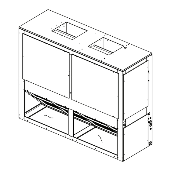
Weights Air Handler Table 2. Constant volume air handler (TWE)— unit and corner weights - (60 Hz) Corner Weights - Vertical Corner Weights - Horizontal Shipping Net Max Tons Model Number Max (lbs) (lbs) TWE060K(3,4,W, 1)A TWE0604(3,4, 1)B TWE090K(1)A/B TWE120K(1)A/B Table 3. - Page 27 Weights Figure 17. Horizontal— TWE 060, 072, 090, 120 Top View Control Box Access Figure 18. Horizontal— TWE 150, 180, 240, 300 Top View Control Box Access SS-SVX016A-EN...
-
Page 28: Accessories
Weights Accessories Table 4. Accessory weights (net lbs.) Discharge Discharge Unit Discharge Plenum and Plenum and Electric Used Hot Water Plenum and Return Air Oversized RIS Isolator Steam Coil Grille with Grille with Heat Min/ Subbase Coil Grille Grille Motor Floor Mount Hydronic Electric... -
Page 29: Installation
Installation Horizontal Suspension NOTICE Equipment Damage! If the air handler will be suspended, use a suspension mounting kit to isolate the unit from the structure. This is Ensure that the refrigerant lines passing through the usually accomplished with spring or rubber isolators, which cabinet are not resting on sharp sheet metal edges are offered as an accessory. -
Page 30: Condensate Piping
Installation Condensate Piping WARNING Fiberglass Wool! The drain pan condensate connection is a female slip joint type for 1” Schedule 40 PVC pipe. Use PVC cement and Exposure to glass wool fibers without all necessary tubing as required (field supplied) to construct a trap. A PPE equipment could result in cancer, respiratory, union or flexible tubing and clamps may be installed if the skin or eye irritation, which could result in death or... -
Page 31: Filter Replacement
To convert from 1-inch filter to a 2-inch filter on units so Trane or others, refer to the appropriate equipped, remove lower access panels from both ends of manufacturer’s literature for allowable waiting periods the air handler. -
Page 32: Unit Power Supply
Installation Unit Power Supply WARNING Proper Field Wiring and Grounding The installer must provide line voltage circuit(s) to the unit main power terminals as shown by the unit wiring Required! diagrams. Adhesive backed diagrams are affixed inside the Failure to follow code could result in death or serious control box cover panel. - Page 33 Installation Figure 23. Symbio jobsite connections Communication signal wires require shielded twisted pairs. Disconnect Switch (By Others) Use Comlink cable with a PVC jacket, 18/1 PR, stranded See Note 1 shield, 25 PF/FT plenum rated for the field communication signal wiring. Refer to wiring diagram schematics for identification of shielded twisted pairs.
-
Page 34: Installation Checklist
Installation Table 5. Recommended thermostat wire size ☐ Inspect all field wiring connections. All connections should be clean and tight. Maximum Wire Length Wire Size ☐ Inspect unit ground connection(s). Ground must comply (Gauge) Physical distance between Unit & T’stat with all applicable codes. -
Page 35: Field Wiring
Installation Field Wiring switch to the Normally Closed position and connect the wires from the switch to the wires from the legacy Refer to the latest version of System Air Conditioners condenser that control this function. Odyssey™ with Symbio™ Controls Wiring and Start-Up, Installation Guide (SS-SVN017*-EN) for instructions on Checkout Procedure field wiring connections. -
Page 36: Start-Up
Start-Up Heating and Cooling Setpoint Figure 24. Supply Fan speed setpoints Arbitration All control function setpoints are set through one of the Symbio™ 700 user interfaces. If no changes are made, the controller will operate, as configured, based on the default settings. - Page 37 Start-Up Each setpoint operates as described below. The Supply Fan Minimum Speed Setpoint correlates to the minimum reference setting in the VFD (25Hz from the Supply Fan Maximum Speed Setpoint (Range: 67- factory). With the Supply Fan Minimum Speed Setpoint at 100%, Default: 100%) its default value of 0%, and parameter 6-14 in the VFD at The Supply Fan Maximum Speed Setpoint correlates to the...
-
Page 38: Symbio™ Condenser Configuration
Start-Up Table 8. Minimum VFD speed ranges Minimum Speed Range Minimum Speed Range Effective Supply Effective Supply (60 Hz) (60 Hz) Fan Maximum Fan Maximum VFD Output (Hz) VFD Output (Hz) 49.8 49.8 59.4 59.4 49.2 49.2 58.8 58.8 48.6 48.6 58.2 58.2... - Page 39 Start-Up Figure 25. Edit configuration Figure 26. Select multi speed and apply changes SS-SVX016A-EN...
-
Page 40: Szvav Air Handler Systems
Start-Up SZVAV Air Handler Systems Figure 27. Verify changes To configure the Symbio 700 for SZVAV air handler systems use the following steps and refer to through Figure 30, p. 1. In the Mobile Service and Installation app, tap Settings. 2. -
Page 41: Field Installed Electric Heat Kits
Start-Up Field Installed Electric Heat Kits Figure 29. System type When Electric Heat Kits are installed into an Odyssey Air Handler paired with a Symbio 700 controlled condenser, configure the Symbio 700 controller so that the electric heat control sequences and output signals will be generated. Use the following steps and refer to through . - Page 42 Start-Up Figure 31. Edit configuration Figure 32. Select primary heating source SS-SVX016A-EN...
- Page 43 Start-Up Figure 33. Apply edits Figure 34. Verify changes SS-SVX016A-EN...
-
Page 44: Electric Heat As Secondary Heat
Start-Up Electric Heat as Secondary Heat (Heat 3. Tap Edit. Pump Systems) 4. Tap Secondary Heating Source. 5. Tap Electric. To configure Electric Heat as Secondary Heat (Heat Pump Systems) use the following steps and refer to Figure 35, p. 6. - Page 45 Start-Up Figure 36. Select secondary heating source SS-SVX016A-EN...
- Page 46 Start-Up Figure 37. Apply changes Figure 38. Verify changes SS-SVX016A-EN...
-
Page 47: Troubleshooting
Troubleshooting WARNING The leak detection sensor offers a visual diagnostic status in the form of one green and one red LED to indicate Live Electrical Components! diagnostic error state. Failure to follow all electrical safety precautions when Table 9. Leak detection system LED status exposed to live electrical components could result in death or serious injury. -
Page 48: Maintenance
Maintenance Perform all of the indicated maintenance procedures at the 3. Set the small O-ring at zero on the force scale of the intervals scheduled. This will prolong the life of the unit and gauge plunger. reduce the possibility of costly equipment failure. 4. -
Page 49: Monthly
For variable frequency drives fiberglass wool. or other energy storing components provided by Trane or others, refer to the appropriate Precautionary Measures: manufacturer’s literature for allowable waiting periods • Avoid breathing fiberglass dust. -
Page 50: Annually (Cooling Season)
Maintenance Annually (Cooling Season) ☐ Check refrigerant piping and fittings for leaks. ☐ Inspect the evaporator coils for dirt and debris. If the The following maintenance procedures must be performed coils appear dirty, clean them. at the beginning of each cooling season to ensure efficient unit operation: Coil Cleaning ☐... -
Page 51: Maintenance Log
Maintenance Maintenance Log SS-SVX016A-EN... -
Page 52: Location
Wiring Diagram Matrix and Device Location Table 11. Wiring schematics and device location Description Applicability Part Number Wiring Schematics Schematics; TWE - SZVAV/2-Speed Fan All TWE Units with Digit 15 = "D" 1213-4779 All TWE Units with Digit 8 = 3, 4, W and Digit Schematics;... -
Page 53: Warranty
Central Air Conditioner THE WARRANTY AND LIABILITY SET FORTH HEREIN ARE IN LIEU OF ALL OTHER WARRANTIES AND This warranty is extended by Trane to the original LIABILITIES, WHETHER IN CONTRACT OR IN purchaser and to any succeeding owner of the real... - Page 54 Notes SS-SVX016A-EN...
- Page 55 Notes SS-SVX016A-EN...
- Page 56 For more information, please visit trane.com or americanstandardair.com. Trane and American Standard have a policy of continuous product and product data improvement and reserve the right to change design and specifications without notice. We are committed to using environmentally conscious print practices.
Need help?
Do you have a question about the Odyssey TWE060K A Series and is the answer not in the manual?
Questions and answers