Sign In
Upload
Download
Table of Contents
Contents
Add to my manuals
Delete from my manuals
Share
URL of this page:
HTML Link:
Bookmark this page
Add
Manual will be automatically added to "My Manuals"
Print this page
×
Bookmark added
×
Added to my manuals
Manuals
Brands
Valleylab Manuals
Medical Equipment
Force FX-C
Service manual
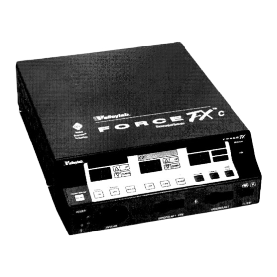
Valleylab Force FX-C Service Manual
Electrosurgical generator with instant response technology
Hide thumbs
1
2
3
4
5
Table Of Contents
6
7
8
9
10
11
12
13
14
15
16
17
18
19
20
21
22
23
24
25
26
27
28
29
30
31
32
33
34
35
36
37
38
39
40
41
42
43
44
45
46
47
48
49
50
51
52
53
54
55
56
57
58
59
60
61
62
63
64
65
66
67
68
69
70
71
72
73
74
75
76
77
78
79
80
81
82
83
84
85
86
87
88
89
90
91
92
93
94
95
96
97
98
99
100
101
102
103
104
105
106
107
108
109
110
111
112
113
114
115
116
117
118
119
120
121
122
123
124
125
126
127
128
129
130
131
132
133
134
135
136
137
138
139
140
141
142
143
144
145
146
147
148
149
150
151
152
153
154
155
156
157
158
159
160
161
162
163
164
165
166
167
168
169
170
171
172
173
174
175
176
177
178
179
180
181
182
183
184
185
186
187
188
189
190
191
192
193
194
195
196
197
198
199
200
201
202
203
204
205
206
207
208
209
210
211
212
213
214
page
of
214
Go
/
214
Contents
Table of Contents
Troubleshooting
Bookmarks
Table of Contents
Conventions Used in this Guide
Table of Contents
List of Figures
Section 1. Introduction
General Description 1·2
List of Components 1·3
Service Personnel Safety 1·3
General 1·3
Fire/Explosion Hazards 1·4
Electric Shock Hazards
Servicing
Calibration 1·6
Cleaning 1·6
Section 2. Controls, Indicators, and Receptacles
Front Panel 2·2
Bipolar Controls 2·3
Bipolar Instrument Receptacle 2·4
Monopolar Cut Controls 2·5
Monopolar Coag Controls 2·6
Monopolar Instrument Receptacles 2·7
REM Alarm Indicator 2·8
Rear Panel 2·9
Footswitch Receptacles 2·10
Monopolar Footswitch Receptacles 2·10
Bipolar Footswitch Receptacle 2·10
Power Entry Module 2·11
Activation Tone Volume Control 2·11
Option Panel 2·12
Section 3. Technical Specifications
Performance Characteristics 3·1
General
Dimensions and Weight 3·2
Operating Parameters 3·2
Transport and Storage 3·2
Duty Cycle
Internal Memory 3·3
Audio Volume
REM Contact Quality Monitor
Serial Port
RF Activation Port
Expansion Port
Low Frequency (50-60 Hz) Leakage Current
High Frequency (RF) Leakage Current
Input Power
Standards and IEC Classifications
Class I Equipment(IEC 601-1)
Type CF Equipment (IEC 601-1)/Defibriliator Proof
Drip Proof (IEC 601-2-2)
Electromagnetic Interference
Electromagnetic Compatibility (IEC 601-1-2 and IEC 601-2-2)
Voltage Transients (Emergency Generator Mains Transfer)
Output Characteristics
Maximum Output for Bipolar and Monopolar Modes
Maximum Output for Ultrasonic Electrosurgery
Available Power Settings in Watts
Output Waveforms
Output Power Vs. Resistance Graphs
Bipolar Graphs
Monopolar Cut Graphs 3·15
Monopolar Coag Graphs
Functional Overview
Instant Response Technology 4·3
Ultrasonic Electrosurgery
Simultaneous Coag 4·3
REM Contact Quality Monitoring System
Control Board
Microcontrollers
Main Microcontroller
Feedback Microcontroller
Shared RAM
Keyboard Interface and Activation Inputs
Power Supply Supervisor Circuit
AID and D/A Conversion
Waveform Generation (T_ON ASIC)
T_ON Average Check
Audio Alarm
Serial Interface
Dosage Error Algorithm
Instant Response Algorithm
Front Panel
Membrane Keyboard
Power Switch
REM Connector/Switch
CEM Mechanism Switch
Display Board
RF Indicator Lamps
REM Indicators
LED and Seven-Segment Display Drivers
CEM Switch Circuit
Mode Selection and Power Control Switches
Footswitch Board
Footswitch Decode Circuit
Audio Circuit
Power Supply/Rf Board
Power Supply/Rf Board Interfaces
High Voltage Power Supply
Low Voltage Power Supply
RF Output Stage
Spark Control Circuit
RF Leakage Reduction Circuit
REM Circuit
Isobloc Circuit
Temperature Sense Circuits
Section 5. Setup, Tests, and Adjustments
Setting up the Generator
Connections for Bipolar or Macrobipolar Surgery
Setting the Bipolar Output
Connections for Monopolar Surgery
Selecting Cut and Coag Modes
Simultaneous Coag
Using Two Generators Simultaneously
Connecting the CUSA Handpiece with CEM Nosecone
Setting the Output Power
Simultaneous Coag with a CUSA System
Changing the Mode
Changing the Power Setting
Activating the Surgical Instrument
Periodic Safety Check
Recommended Test Equipment
Inspecting the Generator and Accessories
Inspecting the Internal Components
Testing the Generator
Verifying REM Function
Confirming Outputs
Check the Output for the Cut Modes
Check the Output for the Coag Modes
Checking Low Frequency Leakage Current
Checking High Frequency Leakage Current
Calibrating the Force FX-C Generator
Preparing for Calibration
Entering Calibration Mode
Exiting Calibration Mode
Verify the Force FX-C Generator Data
Adjust the Calendar
Adjust the Clock
Check and Adjust the REM Oscillator Frequency and Impedance
Check and Adjust the Voltage Sense Gain
Check and Adjust the Reactance Gain
Check and Adjust the ECON Factor
Using the RS-232 Serial Port
Enter the Commands
Disconnect the Computer from the Generator
Section 6. Troubleshooting
Inspecting the Generator
Inspecting the Receptacles
Inspecting the Internal Components
Correcting Malfunctions
Responding to System Alarms
Correcting IC U3 Malfunctions
Correcting IC U6 Malfunctions
Correcting T
Correcting Battery-Backed RAM Malfunctions
Section 7. Replacement Procedures
Interconnect Diagram
Battery Replacement
Control Board Replacement
Display Board Replacement 7·5
Install the Display Board
Display Board Seven-Segment LED Replacement
Fan Replacement
Footswitch Board Replacement
Front Panel Replacement
Remove the Front Panel Assembly
Front Panel REM Module Replacement
Front Panel Power Switch Replacement
Fuse Replacement
Replacing Fuses in the Fuse Drawer 7·13
Replacing the Fuse on the Power Supply/Rf Board
Left Front Heat Sink and Component Replacement 7·15
Remove the Left Front Heat Sink
Replace Left Front Heat Sink Components
Install the Left Front Heat Sink 7·16
Left Rear Heat Sink and Component Replacement
Replace Left Rear Heat Sink Components
Install the Left Rear Heat Sink
Right Heat Sink and Component Replacement 7·20
Remove the Right Heat Sink
Replace Right Heat Sink Components
Install the Right Heat Sink 7·22
Low Voltage Power Supply Replacement 7·23
Install the Low Voltage Power Supply
Power Entry Module Replacement
Install the Power Entry Module
Power Supply/Rf Board Replacement
Remove the Power Supply/Rf Board Assembly
Remove Components from the Old Board
Install Components on the New Board
Install the Power Supply/Rf Board Assembly
Section 8. Repair Policy and Procedures
Responsibility of the Manufacturer
Returning the Generator for Service
Obtain a Return Authorization Number
Clean the Generator
Ship the Generator
Returning Circuit Boards
Service Centers
Section 9. Service Parts
Ordering Replacement Parts
Generator Assembly
Parts List
Front Panel Assembly
Parts List
Control Board Components
Display Board Components
Footswitch Board Components
Power Supply/Rf Board Assembly
Parts List
Power Supply/Rf Board Components
Appendix A. Warranty
Advertisement
Quick Links
1
Periodic Safety Check
Download this manual
SERVICE MANUAL
Force FXTM-C
Electrosurgical Generator
with Instant Response™ Technology
Table of
Contents
Previous
Page
Next
Page
1
2
3
4
5
Advertisement
Table of Contents
Need help?
Do you have a question about the Force FX-C and is the answer not in the manual?
Ask a question
Questions and answers
Related Manuals for Valleylab Force FX-C
Medical Equipment Valleylab ForceTriad User Manual
Energy platform (100 pages)
Medical Equipment Valleylab Force 2 User Manual
Electrosurgical generator (58 pages)
Medical Equipment Valleylab Force 30 Service Manual
(106 pages)
Medical Equipment Valleylab Force 40 Service Manual
(106 pages)
Medical Equipment Valleylab FORCE 4 Service Manual
110v (138 pages)
Medical Equipment Valleylab Force FX-8C Service Manual
Electrosurgical generator with instant response™ technology (218 pages)
Medical Equipment Valleylab LigaSure Service Manual
Vessel sealing generator (168 pages)
Medical Equipment Valleylab SurgiStat II-20 User Manual
Electrosurgical generator (68 pages)
Medical Equipment Valleylab RapidVac 1009803 Service Manual
Smoke evacuator (46 pages)
Medical Equipment Valleylab CUSA EXcel-8 Service Manual
(239 pages)
Medical Equipment Valleylab RapidVac User Manual
Smoke evacuator system (50 pages)
Related Products for Valleylab Force FX-C
Valleylab ForceTriad
Valleylab Force 2
Valleylab Force 30
Valleylab Force 40
Valleylab FORCE 4
Valleylab Force FX-8C
Valleylab Force EZ - C Series
Valleylab Force 2-2 PCH
Valleylab Force 2-8 PCH
Valleylab Force2
Valleylab CUSA EXcel-8
Valleylab LigaSure
Valleylab RapidVac
Valleylab RapidVac 1009803
Valleylab SurgiStat II-20
Table of Contents
Save PDF
Print
Rename the bookmark
Delete bookmark?
Delete from my manuals?
Login
Sign In
OR
Sign in with Facebook
Sign in with Google
Upload manual
Upload from disk
Upload from URL


Need help?
Do you have a question about the Force FX-C and is the answer not in the manual?
Questions and answers