Sign In
Upload
Manuals
Brands
Valleylab Manuals
Inverter
Force EZ - C Series
Valleylab Force EZ - C Series Manuals
Manuals and User Guides for Valleylab Force EZ - C Series. We have
2
Valleylab Force EZ - C Series manuals available for free PDF download: Service Manual
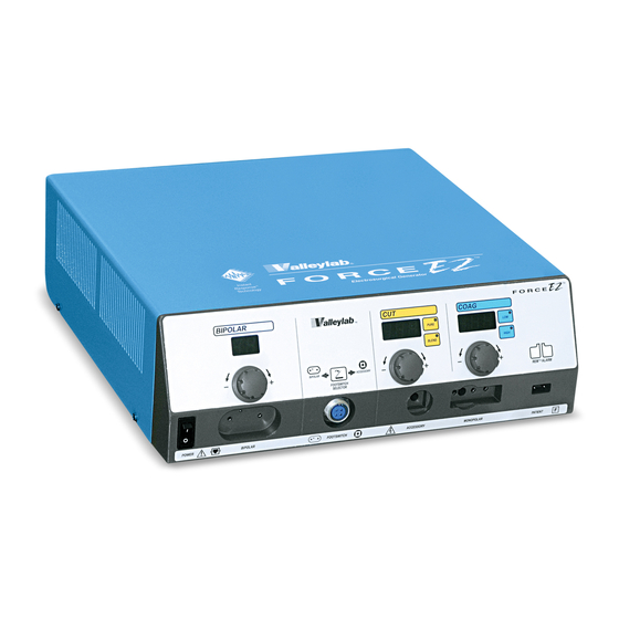
Valleylab Force EZ - C Series Service Manual (208 pages)
Electrosurgical Generator
Brand:
Valleylab
| Category:
Inverter
| Size: 2 MB
Table of Contents
Conventions Used in this Guide
3
Warranty
4
Table of Contents
7
List of Figures
13
Section 1. Service Personnel Safety
15
Safety Information
16
Warnings, Cautions, and Notices
16
General
16
Fire/Explosion Hazards
17
Electric Shock Hazards
18
Servicing
18
Calibration
19
Cleaning
19
Section 2. Introduction
21
General Description
22
List of Components
22
Instant Response Technology
23
Bipolar Modes
23
Monopolar Cut and Coag Modes
23
Cut Modes
23
Coag Modes
24
REM Contact Quality Monitoring System
24
How the REM System Works
25
Electrodes Without the REM Safety Feature
25
Special Features
25
Low (Desiccate) Coag Settings
25
High (Fulgurate) Coag Settings
26
Recall of most Recently Used Modes and Power Settings
26
Default Coag Mode
26
Original Default Settings
26
Section 3. Controls, Indicators, and Receptacles
27
Front Panel
28
Figure 3-1. the Front Panel
28
Rear Panel
32
Option Panel
34
Section 4. Technical Specifications
35
Performance Characteristics
36
General
36
Dimensions and Weight
36
Operating Parameters
36
Transport and Storage
37
Duty Cycle
37
Internal Memory
37
Audio Volume
38
REM Contact Quality Monitor
38
Serial Port
39
RF Activation Port
39
Input Power
40
Low Frequency (50-60 Hz) Leakage Current
41
High Frequency (RF) Leakage Current
41
Standards and IEC Classifications
42
Class I Equipment (IEC 60601-1)
42
Liquid Spillage (IEC 60601-2-2 Clause 44.3)
43
Electromagnetic Interference
43
Electromagnetic Compatibility (IEC 60601-1-2 and IEC 60601-2-2)
43
Voltage Transients (Emergency Generator Mains Transfer)
43
Output Characteristics
48
Available Power Settings in Watts
48
Maximum Output for Force EZ-C Series Electrosurgical Generator Modes
49
Output Waveforms
50
Output Power Vs. Resistance Graphs
51
Figure 4-9. Standard Bipolar Mode @ 100 Ohms - Generator Setting Vs. Output Power
56
Figure 4-11. Pure Mode @ 300 Ohms - Generator Setting Vs. Output Power
57
Figure 4-13. Blend Mode @ 300 Ohms - Generator Setting Vs. Output Power
58
Figure 4-15. Low 1 (Desiccate) Mode @ 500 Ohms - Generator Setting Vs. Output Power
59
Figure 4-16. Low 1 (Desiccate) Mode - Peak Voltage Vs. Output Power
59
Figure 4-17.Low 2 (Desiccate) Mode @ 300 Ohms- Generator Setting Vs. Output Power
60
Figure 4-18. Low 2 (Desiccate) Mode - Peak Voltage Vs. Output Power
60
Figure 4-19. Low 3 (Desiccate) Mode @ 300 Ohms- Generator Setting Vs. Output Power
61
Figure 4-20. Low 3 (Desiccate) Mode - Peak Voltage Vs. Output Power
61
Figure 4-21. High 1 (Fulgurate) Mode @ 500 Ohms- Generator Setting Vs. Output Power
62
Figure 4-22. High 1 (Fulgurate) Mode - Peak Voltage Vs. Output Power
62
Figure 4-23. High 2 (Fulgurate) Mode @ 500 Ohms- Generator Setting Vs. Output Power
63
Figure 4-24. High 2 (Fulgurate) Mode - Peak Voltage Vs. Output Power
63
Section 5. Principles of Operation
65
Figure 5-1. a Block Diagram of the Force EZ-C Series Generator
66
Functional Overview
67
Instant Response Technology
67
REM Contact Quality Monitoring System
67
Control Board
68
Microcontrollers
69
Main Microcontroller
69
Feedback Microcontroller
70
Shared RAM
71
Real-Time Clock
71
I/0 Expansion
71
Keyboard Interface and Activation Inputs
71
Power Supply Supervisor Circuit
72
A/D and D/A Conversion
72
Waveform Generation (T_ON ASIC)
72
T_ON Average Check
73
Audio Alarm
73
Serial Interface
73
Dosage Error Algorithm
74
Instant Response Algorithm
75
Display Board
76
Bipolar, Cut, and Coag Power Setting Encoders
76
RF Indicator Lamps
77
LED and Seven-Segment Display Drivers
77
Mode Selection Switches
78
REM Switch Circuit
79
Front Panel Footswitch Circuit
79
Footswitch Board
80
Power Supply/Rf Board
80
Power Supply/Rf Board Interfaces
81
High Voltage Power Supply
81
Low Voltage Power Supply
84
RF Output Stage
85
Spark Control Circuit
88
RF Leakage Sensing and Reduction Circuit
89
REM Circuit
89
Isobloc Circuit
89
Audio Circuit
90
Footswitch Decode Circuit
92
Temperature Sense Circuit
92
Section 6. Setup, Tests, and Adjustments
93
Setting up the Generator
94
Connections for Bipolar Surgery
96
Setting the Bipolar Output
97
Connections for Monopolar Surgery
97
Figure 6-3. Bipolar Connection (Handswitching Instrument)
97
Set the Cut and Coag Output
99
Setting up the Special Features
100
Using Two Generators Simultaneously
100
Changing the Mode
102
Changing the Power Setting
102
Activating the Surgical Instrument
103
Periodic Safety Check
104
Recommended Test Equipment
104
Inspecting the Generator and Accessories
105
Inspecting the Internal Components
106
Testing the Generator
107
Verifying REM Function
108
Confirming Outputs
108
Checking the Monopolar Output
110
Checking Low Frequency Leakage Current and Ground Resistance
112
Checking High Frequency Leakage Current and Ground Resistance
113
Calibrating the Force EZ-C Series Electrosurgical Generator
114
Preparing for Calibration
116
Entering Calibration Mode
116
Exiting Calibration Mode
117
Calibration Step 1 - Verify the Force EZ-C Series Electrosurgical Generator Data
117
Calibration Step 2 - Adjust the Calendar
118
Calibration Step 3 - Adjust the Clock
119
Calibration Step 4 - Check the REM Impedance
120
Calibration Step 5 - Check and Adjust the Current Sense Gain
121
Calibration Step 6 - Check and Adjust the Voltage Sense Gain
123
Calibration Step 7 - Check and Adjust the Reactance Gain
125
Calibration Step 8 - Check and Adjust the ECON Factor
127
Section 7. Troubleshooting
131
Inspecting the Generator
132
Correcting Malfunctions
133
Responding to System Alarms
141
Correcting Integrated Circuit (IC) Malfunctions
152
Correcting T_ON ASIC Malfunctions
152
Correcting Battery-Backed RAM Malfunctions
154
Section 8. Replacement Procedures
157
Interconnect Diagram
158
Battery
159
Equipment
159
Procedure
159
Control Board
160
Equipment
160
Procedure
160
Display Board
161
Equipment
161
Remove the Display Board
161
Install the Display Board
162
Display Board Seven-Segment LED
163
Footswitch Board Assembly
163
Equipment
163
Front Panel
164
Equipment
164
Remove the Front Panel Assembly
164
Remove and Reinstall the Front Panel Components
165
Install the Front Panel Assembly
166
Front Panel Footswitch Receptacle
166
Front Panel Knob
167
Equipment
167
Procedure
167
Front Panel Power Switch
168
Figure 8-2. Power Switch and Cable Connections
168
Front Panel REM Lever
169
Fuses
169
Replacing Fuses in the Fuse Drawer
169
Replacing the Fuse on the Low Voltage Power Supply
170
Replacing the Fuse on the Power Supply/Rf Board
171
Handle
172
Left Front Heat Sink Component
173
Equipment
173
Remove the Left Front Heat Sink
173
Replace the Left Front Heat Sink Components
174
Install the Left Front Heat Sink
174
Left Rear Heat Sink Component
175
Equipment
175
Remove the Left Rear Heat Sink
175
Replace the Left Rear Heat Sink Components
176
Install the Left Rear Heat Sink
177
Right Heat Sink Component
177
Equipment
177
Remove the Right Heat Sink
177
Replace the Right Heat Sink Components
178
Install the Right Heat Sink
179
Low Voltage Power Supply
180
Equipment
180
Remove the Low Voltage Power Supply
180
Install the Low Voltage Power Supply
181
Power Entry Module
182
Equipment
182
Remove the Power Entry Module
182
Install the Power Entry Module
183
Power Supply/Rf Board
184
Equipment
184
Remove the Power Supply/Rf Board and Heat Sinks
184
Install the Power Supply/Rf Board and Heat Sinks
185
Section 9. Repair Policy and Procedures
187
Responsibility of the Manufacturer
188
Returning the Generator for Service
188
Returning Circuit Boards
189
Service Centers
190
Section 10. Service Parts
191
Ordering Replacement Parts
192
Force EZ-C Series Electrosurgical Generator Assembly
193
Generator Assembly Parts List
195
Control Board Components
197
Footswitch Board Components
198
Power Supply/Rf Board Components
199
Advertisement
Valleylab Force EZ - C Series Service Manual (108 pages)
Electrosurgical Generator
Brand:
Valleylab
| Category:
Portable Generator
| Size: 14 MB
Table of Contents
Service Personnel Safety
8
Fire/Explosion Hazards
9
Electric Shock Hazards
10
General Description
12
Instant Response Technology
12
Cut Modes
12
Front Panel
15
Technical Specifications
18
Transport and Storage
19
Duty Cycle
19
Internal Memory
19
Serial Port
20
RF Activation Port
20
Electromagnetic Interference
22
Functional Overview
34
Main Microcontroller
35
Shared RAM
36
Real Time Clock
36
T_ON Average Check
37
Audio Alarm
37
Serial Interface
37
Instant Response Algorithm
38
Display Board
39
RF Indicator Lamps
39
LED and Seven-Segment Display Drivers
39
High-Voltage Power Supply
41
RF Output Stage
43
Audio Circuit
46
Footswitch Decode Circuit
47
Setting up the Generator
48
Changing the Mode
52
Changing the Power Setting
52
Confirming Outputs
55
Checking High Frequency Leakage Current and Ground Resistance
57
Exiting Calibration Mode
59
Correcting Malfunctions
67
Control Board
81
Install the Display Board
82
Remove the Front Panel Assembly
83
Front Panel Knob
84
Front Panel Power Switch
85
Remove the Low Voltage Power Supply
91
Remove the Power Entry Module
92
Responsibility of the Manufacturer
95
Returning the Generator for Service
95
Step 2 - Clean the Generator
95
Service Centers
96
Warranty
105
Advertisement
Related Products
Valleylab Force FX-8C
Valleylab ForceTriad
Valleylab Force 2-2 PCH
Valleylab Force 2-8 PCH
Valleylab Force 2
Valleylab Force 30
Valleylab Force 40
Valleylab Force FX-C
Valleylab FORCE 4
Valleylab Force2
Valleylab Categories
Medical Equipment
Portable Generator
Inverter
More Valleylab Manuals
Login
Sign In
OR
Sign in with Facebook
Sign in with Google
Upload manual
Upload from disk
Upload from URL